The NTN architecture is designed to bridge the digital divide, enabling seamless connectivity across geographies where traditional ground-based networks are either impractical or economically unfeasible. Key elements of NTN include satellites (transparent or regenerative) that serve as critical intermediaries for transmitting and managing data. Transparent satellites primarily relay signals without processing(often called as Bent Pipe), while regenerative satellites enhance network capabilities by processing data directly onboard.
The architecture offers multiple deployment scenarios, such as those leveraging geostationary orbits (GEO) and low earth orbits (LEO). These deployments support a range of use cases, including steerable beams for flexible coverage and fixed beams that move with the satellite to ensure consistent service. Within the 5G NTN framework, user equipment and relay nodes connect through varied configurations, such as bent-pipe satellite systems or satellite-based gNodeBs (gNB), to provide uninterrupted coverage across land, air, and sea. This integrated approach underscores the transformative potential of NTNs in delivering reliable, high-speed connectivity to even the most remote regions, revolutionizing communication in areas as diverse as aviation, maritime, and rural development.
- Segments and Links
- Orbits and Platform Types
- Payload Type
- Reference Scenarios
- Earth-fixed vs Earth-moving Beams and Cells
- Architecture Options
- Functional Split on a Regenerative Payload
- Deployment Scenario
- Feeder Link Switch-over and Service Link Switch
- From the Study Item to the Rel-17/18 Architecture
- Mapping the Scenarios onto Real Systems
Segments and Links
Before going into payload types and architecture options, it is worth fixing the vocabulary. Whatever the orbit, the payload or the deployment option is, every NTN can be described with the same three segments and the same small set of radio links. Almost every term used in the rest of this page (feeder link, service link, gateway, ISL, field of view) belongs to one of these groups, so if these are clear the rest of the page becomes mostly bookkeeping.
< What '3GPP work on NTN' actually covers - an altitude ladder, not just satellites >

The illustration above is a good reminder that 'non-terrestrial' in the widest sense is not only about satellites. It is an altitude ladder : satellite networks at 600 km and above, a High Altitude Platform Station acting as an IMT base station (HAPS/HIBS) at around 20 km, air-to-ground networks serving aircraft at around 10 km, and UAV (drone) at around 150 m. 3GPP NTN work items cover the satellite and HAPS part of this ladder, whereas UAV is handled as a separate work stream even though it is 'non-terrestrial' in plain English. When a specification says 'NTN', it normally means the spaceborne/HAPS part only.
< End to end view of an NTN : segments, links and service areas >
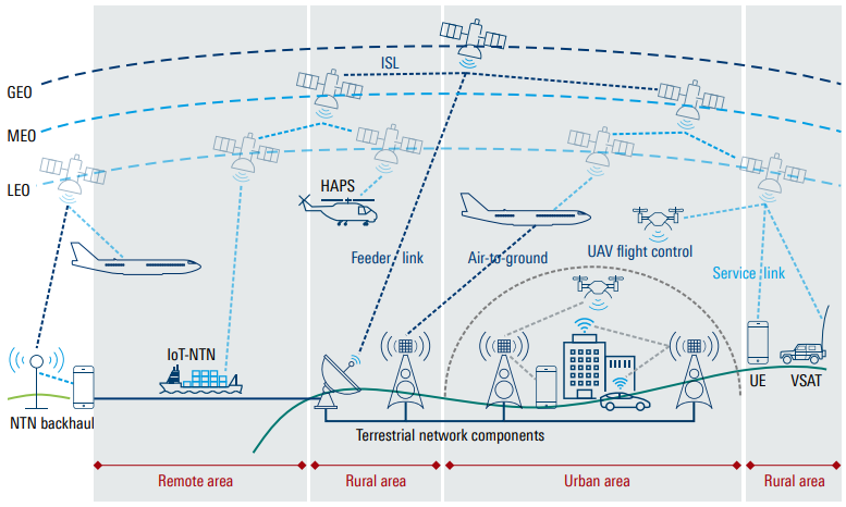
This second illustration packs almost the whole NTN vocabulary into one picture. Reading it from top to bottom :
-
Satellite : GEO, MEO or LEO. It carries the NTN payload, which is either transparent or regenerative (described in the next section).
-
HAPS (High Altitude Platform Station) : a stratospheric platform (balloon, solar aircraft, airship) at roughly 8 - 50 km. From a 3GPP point of view it is treated exactly like a very low satellite - same architecture options, just much smaller delay and Doppler.
-
UAS / UAV : the platform itself can carry a payload, but a UAV is also an NTN user in the 'UAV flight control' case shown in the picture.
-
NTN Gateway (Sat-gateway) : the earth station that terminates the feeder link. It is a large tracking antenna, not a cell site - see the practical note in Feeder Link Switch-over.
-
gNB and 5GC : where they physically sit is exactly what distinguishes the architecture options. In a transparent system both are on the ground behind the gateway; in a regenerative system the gNB (or a part of it) moves on board.
-
Terrestrial network components : NTN is not a replacement for the terrestrial network, it is an extension of it. The green line in the picture is the terrestrial transport network that the gateway hands the traffic over to.
-
Handheld UE (Direct-to-Device) : an ordinary smartphone with an omnidirectional, roughly 0 dBi antenna and 200 mW class 3 power. This is the hardest case link-budget-wise and it is the reason S band (around 2 GHz) is used for the service link.
-
VSAT : a directive terminal (up to 60 cm aperture, up to 20 W, 1.2 dB noise figure) that can be fixed or mounted on a truck, ship or aircraft. Much better link budget, so Ka band becomes usable.
-
IoT-NTN device : NB-IoT/eMTC over satellite, typically very low data rate and very tolerant of latency. Handled by a separate set of specifications (TR 36.763 / TS 36.331) but the same architecture picture applies.
-
Relay node : a terminal that terminates the satellite link on behalf of many local users (an aircraft cabin, a ship, a train). This is the case covered by architecture options A3 and A4.
-
Service link : platform <-> UE. This is the link that 3GPP standardises as NR (or NB-IoT/eMTC). In the reference scenarios it is always '3GPP defined New Radio'.
-
Feeder link : platform <-> NTN gateway. Note in the reference table that this one is '3GPP
or non-3GPP defined radio interface'. In a transparent payload the feeder link carries the same NR waveform (just frequency-translated), so it is effectively 3GPP; in a regenerative payload it carries NG/F1 signalling and can be any proprietary satellite link. -
ISL (Inter-Satellite Link) : platform <-> platform. Only meaningful for a regenerative constellation (Scenario D), because a transparent satellite has nothing to route. ISL is what allows a LEO constellation to reach a gateway that is not in the current satellite's field of view.
-
Air-to-ground link : aircraft <-> terrestrial tower, shown in the picture for completeness. It is 'non-terrestrial' in the wide sense but is not part of the NR-NTN specifications.
Orbits and Platform Types
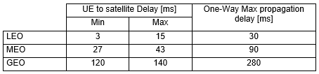
The orbit determines almost everything else in the architecture : the propagation delay, the Doppler shift, how long a satellite stays visible, whether a cell can stay still on the ground, and how many satellites are needed for continuous coverage. The table below summarises the platform types that appear in the NTN specifications.
|
Platform |
Altitude |
Apparent motion |
One-way delay (UE to platform) |
Architectural consequence |
|---|---|---|---|---|
|
GEO |
35,786 km |
Effectively stationary (station keeping box) |
Approx. 120 - 140 ms |
Beams are naturally Earth-fixed, Doppler is negligible (0.93 ppm), but the round trip delay dominates every timer in the protocol stack. A single satellite covers a continent, so one gateway can serve a huge area. |
|
MEO |
Approx. 7,000 - 25,000 km |
Moving, several hours of visibility |
Approx. 27 - 43 ms |
A compromise between GEO and LEO. TR 38.821 does not define a MEO reference scenario, so MEO is normally analysed by interpolating between the GEO and LEO cases. |
|
LEO |
600 km / 1,200 km (reference values) |
7.56 km/s at 600 km - a few minutes of visibility |
Approx. 3 - 15 ms |
Low delay, but everything moves : up to 24 ppm Doppler, continuously changing timing advance, and a satellite (and therefore the cell, and possibly the gateway) has to be handed over every few minutes. A constellation of many satellites is mandatory for continuity. |
|
HAPS / HIBS |
8 - 50 km (typically approx. 20 km) |
Quasi-stationary (station keeping over one area) |
Well below 1 ms |
Delay and Doppler are close to a terrestrial macro cell, so almost no NTN-specific protocol adaptation is needed. This is Deployment-D5 in TR 38.811. |
This figure is quoted directly in TR 38.821 Table 7.1-1 as the 'relative speed of satellite with respect to earth' for the 600 km LEO scenarios, but it is not an arbitrary constant - it is just the circular orbit velocity, and it is worth being able to reproduce it :
v = sqrt( μ / r )
where μ = 398,600 km3/s2 is the Earth's standard gravitational parameter and r is the orbital radius measured from the
v = sqrt( 398,600 / 6,971 ) = 7.56 km/s
The same formula gives 7.26 km/s at 1,200 km and 3.07 km/s at GEO. The GEO value is the interesting one : at 35,786 km the orbital period works out to exactly one sidereal day, which is what makes the satellite appear to hang motionless over one spot - and that altitude is a consequence of the formula, not a choice.
vground = v x Re / r = 7.56 x 6,371 / 6,971 = approx. 6.9 km/s
The distinction matters depending on what you are calculating. Use 7.56 km/s for Doppler and for delay drift, because those depend on the satellite's actual velocity. Use approximately 6.9 km/s for how long a moving beam dwells over a given place, because that depends on the ground track. The two differ by about 9 %, which is small enough to ignore in a rough estimate and large enough to notice in a link budget or a handover timer.
< TR38.811 - typical one-way propagation delay per orbit >
Payload Type
The NTN payload type refers to the technology and functional capabilities of the payload installed on a spaceborne or airborne platform, such as a satellite or high-altitude platform. The payload is responsible for transmitting, receiving, and possibly processing communication signals as part of the NTN infrastructure. There are two primary types of NTN payloads: non-regenerative (or "bent-pipe" or "transparent") and regenerative (or "non-transparent").
Non-Regenerative Payload : Also referred to as the "bent-pipe payload" or "transparent mode," this type of payload acts as an analogue RF repeater. The spaceborne or airborne platform equipped with a non-regenerative payload has no on-board signal processing capabilities. Instead, it simply receives the uplink RF signal, changes the frequency carrier, filters the signal, amplifies it, and transmits it back down via the downlink. This type of payload is cost-effective and simpler to implement since it relies on ground-based processing systems for complex operations. However, its functionality is limited to signal relay without enhancing or managing the signal.Regenerative Payload : Also known as the "non-transparent mode," a regenerative payload adds on-board processing capabilities to the spaceborne or airborne platform. In addition to performing basic RF operations like filtering, frequency conversion, and amplification, a regenerative payload can also handle tasks such as demodulation, decoding, switching, routing, encoding, and modulation. Effectively, this type of payload includes base station-like functionality within the platform, enabling it to manage signals more independently. Regenerative payloads reduce the dependence on ground infrastructure and improve efficiency, as the processed data requires less bandwidth and can be routed more intelligently.
< TR 38.811 v15.4.0-Figure 4.6-1: NTN Beam patterns >
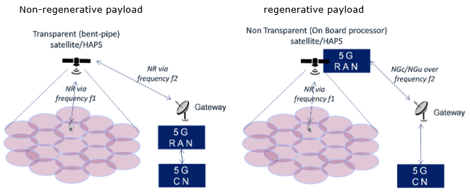
This one picture answers most of the questions people ask about payload types, so it is worth going through it label by label.
-
Two frequencies, always : both sides of the figure show 'NR via frequency f1' on the service link and 'frequency f2' on the feeder link. The two links must use different frequencies (or at least different polarisation/beams) because the satellite is transmitting and receiving at the same time on the same platform. f1 is typically S band for handheld access, f2 is typically Ka band for the gateway.
-
Left (non-regenerative) : the feeder link is labelled '
NR via frequency f2 '. That is the key point - the bent-pipe satellite is relaying the NR waveform itself. The 5G RAN box sits on the ground behind the gateway, so the Uu interface is stretched all the way from the UE, up to the satellite, back down to the gateway and into the gNB. -
Right (regenerative) : the feeder link is labelled '
NGc/NGu over frequency f2 '. The NR waveform is terminated on board (the '5G RAN' box has moved onto the satellite), and what travels over the feeder link is core network signalling and user plane, not NR. This is why the feeder link in a regenerative system is allowed to be a completely non-3GPP proprietary satellite link. -
The 5G CN stays on the ground in both cases : notice that the '5G CN' box never moves onto the satellite in this figure. TR 38.821 studies the RAN on board, not the core. Putting the core in orbit is outside the scope of the 3GPP NTN work.
-
The beam footprints look identical : the ellipse pattern on the ground is the same on both sides. Payload type and beam pattern are two independent design choices - a bent-pipe satellite can have steerable Earth-fixed beams, and a regenerative satellite can have beams that simply move with it.
|
Non-Regenerative (Transparent / Bent Pipe) |
Regenerative (Non-Transparent) |
|
|---|---|---|
|
On-board function |
Filter, frequency conversion, amplify. Analogue RF repeater only. |
Everything above plus demodulation, decoding, switching/routing, encoding, modulation. |
|
Where the gNB is |
On the ground, behind the NTN gateway. The satellite is effectively a very high Remote Radio Head. |
On board (whole gNB, or gNB-DU only with the gNB-CU on the ground). |
|
What the Uu interface spans |
UE <-> satellite <-> gateway <-> gNB (service link + feeder link) |
UE <-> satellite (service link only) |
|
What the feeder link carries |
The NR waveform, frequency-translated. Any impairment on the feeder link is seen directly by the UE. |
NG (N2/N3) or F1 traffic. Can be a proprietary, non-3GPP satellite link. |
|
GEO max round trip delay (TR 38.821) |
541.46 ms |
270.73 ms |
|
LEO max round trip delay (TR 38.821) |
25.77 ms (600 km) / 41.77 ms (1200 km) |
12.89 ms (600 km) / 20.89 ms (1200 km) |
|
Inter-Satellite Link |
Not meaningful (nothing to route on board) |
Possible - the satellite can forward packets to a peer that has a gateway in view |
|
Satellite complexity, mass, power, cost |
Low. Long design life, easy to certify for space. |
High. Needs radiation-tolerant baseband processing and thermal budget for it. |
|
Upgradability |
Excellent - the gNB is on the ground and can be upgraded to a new 3GPP release at any time without touching the satellite. |
Limited - a release upgrade means a software update in orbit, and the on-board hardware is frozen at launch for 5 - 15 years. |
|
Feeder link bandwidth needed |
Proportional to the total radio bandwidth of all beams (the raw waveform is relayed) |
Proportional to the actual user throughput (already decoded), so significantly less |
|
3GPP status |
Specified normatively from Rel-17 |
Studied in TR 38.821, not specified normatively as of Rel-18 |
Reference Scenarios
Following two illustration describes two typical scenarios of Non-Terrestrial Networks (NTN), showcasing how they use satellites or Unmanned Aircraft Systems (UAS) to provide communication services to user equipment (UE) on the ground
< TR38.821 v16.2.0-Figure 4.1-1: Non-terrestrial network typical scenario based on transparent payload >
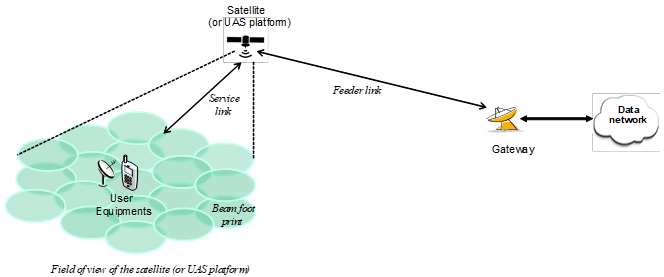
< TR38.821 v16.2.0-Figure 4.1-2: Non-terrestrial network typical scenario based on regenerative payload >
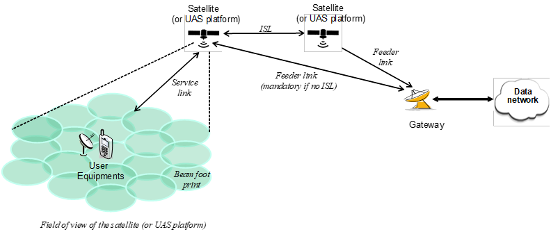
Let's break down the key elements:
-
Sat-gateways: These act as the bridge between the NTN and existing ground-based networks (like the internet). They could be thought of as specialized ground stations.
-
Feeder Link: This is the radio connection between the sat-gateway(s) and the satellite/UAS. It's how data gets to and from the satellite/UAS.
-
Service Link: This is the radio connection between the user equipment (like your phone) and the satellite/UAS. This is how you send and receive data.
-
Satellite/UAS Platform: This is the core of the NTN, providing the communication relay in the sky. It can have either a transparent or regenerative payload (more on that below).
-
Beam Footprints: The satellite/UAS generates multiple beams to cover a specific service area. These beams have a footprint on the ground, often shaped like an ellipse.
-
Field of View: This is the area on the ground that the satellite/UAS can "see" and provide service to, limited by its antenna design and minimum elevation angle.
-
In this setup, the satellite/UAS acts as a simple repeater. It receives signals, amplifies them, and transmits them back down. Think of it like a mirror reflecting light.
-
Key Feature: The signal is not processed or altered in any way onboard the satellite/UAS.
-
Here, the satellite/UAS has more advanced capabilities. It can demodulate, decode, and even route signals. It's like having a mini base station in space.
-
Key Feature: This allows for more efficient use of bandwidth and potentially better performance.
-
ISL (Inter-Satellite Links): This scenario often includes connections between satellites, enabling them to work together as a network. This is particularly useful for constellations of multiple satellites.
-
Complexity: Regenerative payloads are more complex and expensive than transparent payloads.
-
Latency: Regenerative payloads can introduce slightly more latency due to the onboard processing.
-
Coverage: The choice of payload and satellite/UAS type can impact the coverage area and service quality.
-
Applications: Different payload types might be better suited for different applications (e.g., voice calls, internet access, data collection).
There can be various scenarios in terms of how non-terrestrial networks can connect users to the internet. It focuses on six different scenarios, each with unique characteristics. These scenarios consider factors like satellite orbits, how the signal is processed, and whether satellites communicate with each other.
The scenarios are divided into two main categories: those using transparent satellites and those using regenerative satellites. Transparent satellites simply relay the signal without any processing, while regenerative satellites have more advanced capabilities, similar to a ground-based base station.
Within each category, there are scenarios involving satellites in geostationary orbit (GEO) and low Earth orbit (LEO). GEO satellites stay in a fixed position relative to the ground, while LEO satellites move across the sky. The scenarios also consider whether the satellite beams are fixed or steerable, which affects how the coverage area changes over time.
< TR38.821 v16.2.0-Table 4.2-1: Reference scenarios >
|
Transparent Satellite |
Regenerative Satellite |
|
|---|---|---|
|
GEO based non-terrestrial access network |
Scenario A |
Scenario B |
|
LEO based non-terrestrial access network: steerable beams |
Scenario C1 |
Scenario D1 |
|
LEO based non-terrestrial access network: the beams move with the satellite |
Scenario C2 |
Scenario D2 |
The letter is not arbitrary, it encodes two independent decisions. Once you internalise the pattern you can decode any scenario label without looking the table up :
-
A / B = GEO, C / D = LEO. (The orbit decides the delay and the Doppler.)
-
A / C = transparent, B / D = regenerative. (The payload decides where the gNB is.)
-
The trailing digit exists only for LEO, because only a moving satellite has to make the choice : 1 = steerable beams pointing at a fixed spot on the Earth, 2 = beams that simply move with the satellite. A GEO satellite is already stationary with respect to the ground, so the question does not arise.
So 'Scenario D2' unpacks to : LEO, regenerative payload (gNB on board), beams moving with the satellite. That single label already tells you the round trip delay is around 13 ms, that ISL is possible, and that the cell on the ground is sweeping across the surface at roughly 6.9 km/s.
< TR38.821 v16.2.0-Table 4.2-2: Reference scenario parameters >
|
Scenarios |
GEO based non-terrestrial access network (Scenario A and B) |
LEO based non-terrestrial access network (Scenario C & D) |
|---|---|---|
|
Orbit type |
Notional station keeping position fixed in terms of elevation/azimuth with respect to a given earth point |
Circular orbiting around the earth |
|
Altitude |
35,786 km |
600 km / 1,200 km |
|
Spectrum (service link) |
<6 GHz (e.g., 2 GHz) >6 GHz (e.g., DL 20 GHz, UL 30 GHz) |
Same as GEO |
|
Max channel bandwidth capability (service link) |
30 MHz for band < 6 GHz; 1 GHz for band > 6 GHz |
Same as GEO |
|
Payload |
Scenario A: Transparent (including radio frequency function only) |
Scenario C: Transparent (including radio frequency function only) |
|
Inter-Satellite Link |
No |
Scenario C: No |
|
Earth-fixed beams |
Yes |
Scenario C1: Yes (steerable beams) |
|
Max beam footprint size (edge to edge) regardless of the elevation angle |
3500 km |
1000 km |
|
Min Elevation Angle |
10° for service link and 10° for feeder link |
10° for service link and 10° for feeder link |
|
Max distance between satellite and user equipment at min elevation angle |
40,581 km |
1,932 km (600 km altitude) |
|
Max Round Trip Delay (propagation delay only) |
Scenario A: 541.46 ms (service and feeder links) |
Scenario C: 25.77 ms (600 km); 41.77 ms (1200 km) |
|
Max differential delay within a cell |
10.3 ms |
3.12 ms and 3.18 ms for 600 km and 1200 km respectively |
|
Max Doppler shift (earth-fixed user equipment) |
0.93 ppm |
24 ppm (600 km); 21 ppm (1200 km) |
|
Max Doppler shift variation (earth-fixed user equipment) |
0.000045 ppm/s |
0.27 ppm/s (600 km); 0.43 ppm/s (1200 km) |
|
User equipment motion on the earth |
1200 km/h (e.g., aircraft) |
Possibly 1200 km/h (e.g., aircraft) |
|
User equipment antenna types |
Omnidirectional antenna (linear polarisation), assuming 0 dBi |
Directive antenna (up to 60 cm equivalent aperture diameter in circular polarisation) |
|
User equipment Tx power |
Omnidirectional antenna: UE power class 3 with up to 200 mW |
Directive antenna: Up to 20 W |
|
User equipment Noise figure |
Omnidirectional antenna: 7 dB |
Directive antenna: 1.2 dB |
|
Service Link |
3GPP defined New Radio |
3GPP defined New Radio |
|
Feeder Link |
3GPP or non-3GPP defined Radio interface |
3GPP or non-3GPP defined Radio interface |
Table 4.2-2 above lists the scenario parameters as they are defined. The table below (from the propagation delay clause of the same TR) is the same six scenarios re-expressed as the numbers a protocol designer actually has to live with - beam size, minimum and maximum delay, and how fast the delay changes. It is worth putting the two tables side by side, because this is where the architecture choice turns into concrete protocol impact.
< TR38.821 v16.2.0-Table 7.1-1: Propagation delay per NTN scenario >
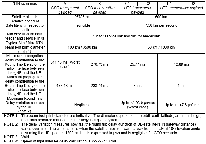
Three numbers in this table drive most of the NTN-specific design work :
-
The absolute delay (up to 541 ms round trip for GEO transparent) breaks every protocol timer that was designed on the assumption of a sub-millisecond air interface - RACH response windows, HARQ round trip, RLC/PDCP timers, RRC timers. This is handled with the K_offset / K_mac scheduling offsets and with the option to disable HARQ feedback.
-
The differential delay across the beam (the gap between the min and max column, e.g. 477.48 ms vs 541.46 ms for GEO) is what makes a single RACH occasion unusable without a per-UE pre-compensation. A UE at the centre of a 3500 km footprint and a UE at its edge are tens of milliseconds apart. This is why every NTN UE must have GNSS and must apply its own timing advance before it ever transmits. See NTN Timing Advance and NTN RACH.
-
The delay variation (up to +/- 93 us/s for LEO transparent, negligible for GEO) means the timing advance is not a one-off correction but something that has to be tracked continuously. It is also the reason the network has to broadcast satellite ephemeris - the UE needs to predict the delay, not just measure it.
Earth-fixed vs Earth-moving Beams and Cells
The '1' and '2' suffix in Scenario C1/C2/D1/D2 looks like a minor detail in the reference table, but it is one of the biggest architectural forks in NTN. It decides whether the cell that a UE is camped on stands still or sweeps across the ground at roughly 6.9 km/s (the ground track speed of a 600 km satellite orbiting at 7.56 km/s), and therefore whether NTN mobility looks like terrestrial mobility or like something completely new.
-
The satellite steers its beams (mechanically, or electronically with a phased array) so that the footprint stays pointed at the same geographic area while the satellite passes overhead.
-
From the UE's point of view the cell is stationary. Cell selection, measurement and handover behave much like a terrestrial network, and a stationary UE can stay in the same cell for a long time.
-
The catch : a LEO satellite can only keep a beam pointed at one spot for a few minutes before the geometry runs out (the beam would have to point below the minimum elevation angle). At that point the whole cell has to be
handed over to the next satellite in the constellation. 3GPP calls the result a quasi-Earth-fixed cell - fixed for a while, then switched. -
Because the switch is predictable from the ephemeris, it can be scheduled rather than triggered by measurements. This is the basis of the time/location-based conditional handover introduced for NTN.
-
The beams are fixed relative to the satellite body, so the footprint slides across the ground with the satellite. This is the simplest possible payload - no beam steering at all.
-
From the UE's point of view the cell is moving. Even a completely stationary UE will be handed over repeatedly, simply because the cell has left. With a 1000 km footprint whose ground track moves at about 6.9 km/s, a UE sits in one cell for roughly two and a half minutes at best.
-
Conventional measurement-based handover is a poor fit here : the source and target beams come from the same satellite (or from a satellite at almost the same distance), so RSRP gives very little discrimination. Location and time are far better triggers than signal strength, which is again why GNSS and ephemeris are mandatory.
-
Tracking areas become awkward. If the cell moves, the cell-to-TAC mapping cannot be static, so NTN allows a cell to broadcast a TAC that changes as it sweeps, and mobility registration is driven by geography rather than by cell identity.
|
Earth-fixed / quasi-Earth-fixed cell |
Earth-moving cell |
|
|---|---|---|
|
Scenarios |
A, B (GEO, naturally); C1, D1 (LEO, by steering) |
C2, D2 |
|
Payload requirement |
Steerable / phased array antenna |
Fixed antenna - simplest payload |
|
Handover cause for a stationary UE |
Only when the serving satellite sets (a few minutes for LEO, never for GEO) |
Continuously, because the cell itself moves away |
|
Best handover trigger |
Time-based (the switch instant is known from ephemeris) |
Location-based / time-based; RSRP alone is not discriminative |
|
Tracking area handling |
Conventional - a cell keeps serving the same geography |
TAC broadcast has to change as the cell sweeps over TA boundaries |
|
Typical use |
Broadband and voice, where session continuity matters |
IoT and messaging, where a short visit from a passing cell is enough |
Architecture Options
Four distinct Non-Terrestrial Network (NTN) architecture options are proposed and each demonstrating a different approach to integrating satellite or aerial platforms into 5G systems. These options explore variations in how user equipment (UEs) and relay nodes connect to the core network through these non-terrestrial elements. Some architectures utilize the satellite/aerial platform as a simple relay, transparently passing signals between ground stations and UEs or relay nodes. Others leverage the platform's processing capabilities by placing gNB functions onboard, enabling direct communication with UEs or relay nodes. This diversity in architectural design offers flexibility in deploying NTNs to extend 5G coverage and capacity, particularly in areas where terrestrial networks are challenging to implement
< TR38.811 v15.4.0-Table 4.7-1: 5G system elements mapping in NTN architecture >
|
NTN Architecture Options |
NTN Terminal |
Space or HAPS |
NTN Gateway |
|---|---|---|---|
|
A1: Access network serving UEs via bentpipe satellite/aerial |
UE |
Remote Radio Head (Bent pipe relay of Uu radio interface signals) |
gNB |
|
A2: Access network serving UEs with gNB on board satellite/aerial |
UE |
gNB or Relay Node functions |
Router interfacing to Core network |
|
A3: Access network serving Relay Nodes via bent pipe satellite/aerial |
Relay Node |
Remote Radio Head (Bent pipe relay of Uu radio interface signals) |
gNB |
|
A4: Access network serving Relay Nodes with gNB on board satellite/aerial |
Relay Node |
gNB or Relay Node functions |
Router interfacing to Core network |
Each of the options can be presented as illustrations as below.
< Based on TR38.811 v15.4.0 - 4.7 Non-Terrestrial Network architecture options>
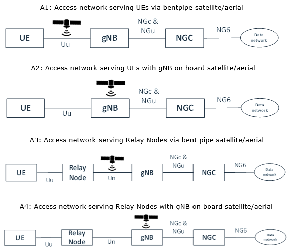
Followings are brief description for each options : (
- Option A: Simple Relay/Bent Pipe
- Imagine the satellite or high-altitude platform like a mirror reflecting a special kind of 5G signal ("Satellite friendly" NR signal). It simply bounces the signal between your phone and the ground station (gNB) without changing it.
- Option B: Mini Base Station in the Sky
- Here, the satellite or platform is more sophisticated. It has some of the same equipment as a ground base station, allowing it to directly communicate with your phone. Think of it as a mini cell tower in space.
- Option C: Relay for Faraway Places
- This is similar to Option A, but instead of connecting directly to your phone, it connects to a relay station on the ground. This relay station then communicates with your phone. This is helpful for extending coverage to very remote areas.
- Option D: Advanced Relay for Faraway Places
- This combines the ideas of Option B and C. The satellite or platform has base station equipment and connects to a relay station on the ground. This offers both advanced processing and extended coverage.
The four diagrams look almost identical at first glance. The trick is to ignore the boxes and look only at
-
Uu : the 3GPP radio interface between a UE and a gNB. In A1 and A3 the satellite is drawn on the Uu line - that is the graphical definition of a bent pipe. The Uu interface simply passes through it.
-
Un : the radio interface between a Relay Node and its donor gNB. It appears only in A3 and A4, which are the two relay-based options. The UE still sees a normal Uu towards the relay and is completely unaware that a satellite exists.
-
NGc & NGu : the control plane and user plane between the gNB and the 5G core (N2 and N3 in the TS 23.501 naming). In A2 and A4 the satellite sits before this line, i.e. the satellite
is the gNB, and it is NG traffic that goes down the feeder link. -
NG6 : the reference point between the core (UPF) and the external data network. It is identical in all four options - the choice of NTN architecture never changes what the data network sees.
Put differently, the four options are a 2x2 matrix of two independent questions :
|
Satellite is a bent pipe |
Satellite has the gNB on board |
|
|---|---|---|
|
The NTN terminal is the end user device (direct access) |
A1 |
A2 |
|
The NTN terminal is a Relay Node serving local users (indirect access) |
A3 |
A4 |
The horizontal axis is the payload type discussed earlier (A1/A3 transparent, A2/A4 regenerative). The vertical axis is a completely different question :
< Mixed platforms in one network : direct access, relayed access and an airborne relay >
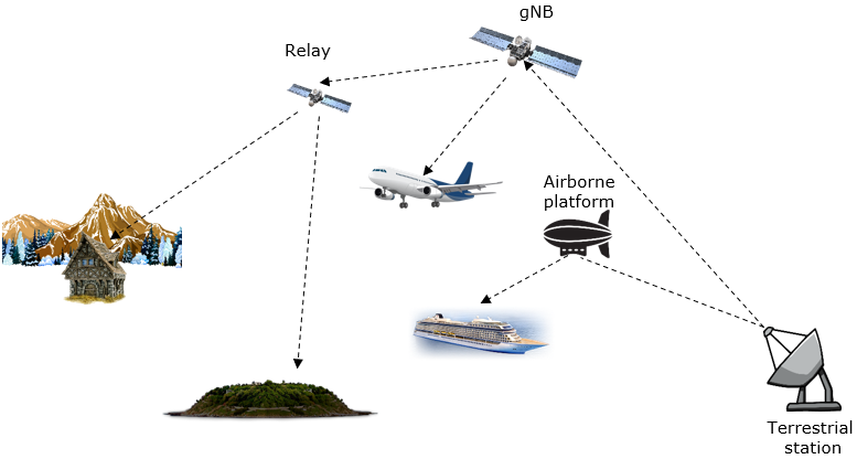
The picture above shows why these options are not mutually exclusive in a real deployment. The same constellation can act as a gNB for one link, as a relay towards another satellite, and as a feeder towards an airborne platform which in turn serves a ship. A remote cabin, an island, an aircraft and a cruise ship can each be served by a different architecture option while sharing the same space assets and the same terrestrial station.
-
A1 is the cheapest satellite and the most expensive spectrum. The feeder link has to relay the raw waveform of every beam, so feeder bandwidth scales with total radio bandwidth. On the other hand the gNB is on the ground, so the operator can upgrade it freely and a single gNB can be shared between several satellites.
-
A2 halves the UE-visible delay and cuts the feeder link bandwidth to the actual traffic, but the gNB is frozen in orbit at launch and every satellite needs its own NG association with the core. It also raises the question of what happens when the satellite has no gateway in view - which is exactly the problem ISL solves.
-
A3 is the classic satellite backhaul / trunking case, and it is by far the easiest one to deploy because the relay terminal is a directive antenna. Deployment-D1 in the table below is exactly this.
-
A4 gives the best of both, at the highest system complexity - on-board processing and a relay node, meaning two 3GPP radio interfaces stacked on top of each other.
Functional Split on a Regenerative Payload
'gNB on board' is not a single design. Because the NG-RAN architecture already allows a gNB to be split into a Central Unit (gNB-CU) and one or more Distributed Units (gNB-DU) connected by the F1 interface, a regenerative payload can carry either the whole gNB or just the DU part. TR 38.821 studies both, and the choice has real consequences for what has to fly.
|
Full gNB on board |
gNB-DU on board, gNB-CU on the ground |
|
|---|---|---|
|
What the feeder link carries |
NG (N2/N3) towards the 5GC |
F1-C and F1-U towards the gNB-CU |
|
On-board protocol stack |
PHY, MAC, RLC, PDCP, SDAP, RRC - everything |
PHY, MAC, RLC only. PDCP/SDAP/RRC stay on the ground. |
|
Where RRC decisions are taken |
In orbit - RRC signalling never has to cross the feeder link |
On the ground - every RRC message crosses the feeder link, adding one feeder round trip |
|
Handover between satellites |
Inter-gNB handover (Xn or NG based), and Xn between satellites needs ISL |
Can be an intra-gNB (inter-DU) handover if both satellites are served by the same CU - considerably lighter signalling |
|
Impact on the core network |
Every satellite is a separate NG-RAN node with its own N2 association |
The whole constellation can appear to the 5GC as a small number of gNBs |
|
Payload burden |
Highest - full stack plus the state of every connected UE |
Lower - the heavy, stateful upper layers stay on the ground |
Deployment Scenario
There are various different deployment scenario that we can think of. 5 different deployment options are defined in TR 38.811 as summarized below.
These deployments vary in terms of the platform's orbit (GEO or Non-GEO), altitude (ranging from 600 km down to 8 km for UAS), and the frequency used for communication with user equipment (around 2 GHz or 20 GHz).
The table also outlines differences in beam pattern (fixed or moving), duplexing mode (FDD), channel bandwidth (up to 2 * 800 MHz), and supported NTN architecture options. Furthermore, it specifies the type of terminal used in each deployment, whether it's a Very Small Aperture Terminal (VSAT) for relay nodes or a 3GPP class 3 UE for direct user access.
Each deployment option caters to different scenarios and use cases. For instance, D1 and D2 utilize GEO satellites for indirect access via relay nodes, while D3 and D4 employ Non-GEO satellites for direct user access. D5 focuses on UAS for low-latency services with both indoor and outdoor coverage. The table concludes by listing the main rationales and supported use cases for each deployment, ranging from enhanced mobile broadband (eMBB) to public safety and IoT services.
< TR38.811 v15.4.0 - Table 5.1-1: Reference Non-Terrestrial Network Deployment scenarios to be considered in the NR-NTN study >
|
Main Attributes |
Deployment-D1 |
Deployment-D2 |
Deployment-D3 |
Deployment-D4 |
Deployment-D5 |
|---|---|---|---|---|---|
|
Platform orbit and altitude |
GEO at 35,786 km |
GEO at 35,786 km |
Non-GEO down to 600 km |
Non-GEO down to 600 km |
UAS between 8 km and 50 km, including HAPS |
|
Carrier Frequency on the link between Air/space-borne platform and UE |
Around 20 GHz for DL, Around 30 GHz for UL (Ka band) |
Around 2 GHz for both DL and UL (S band) |
Around 2 GHz for both DL and UL (S band) |
Around 20 GHz for DL, Around 30 GHz for UL (Ka band) |
Below and above 6 GHz |
|
Beam pattern |
Earth fixed beams |
Earth fixed beams |
Moving beams |
Earth fixed beams |
Earth fixed beams |
|
Duplexing |
FDD |
FDD |
FDD |
FDD |
FDD |
|
Channel Bandwidth (DL + UL) |
Up to 2 * 800 MHz |
Up to 2 * 20 MHz |
Up to 2 * 20 MHz |
Up to 2 * 800 MHz in mobile use and 2 * 1800 MHz in fixed use |
Up to 2 * 80 MHz |
|
NTN architecture options (See clause 4) |
A3 |
A1 |
A2 |
A4 |
A2 |
|
NTN Terminal type |
Very Small Aperture Terminal (fixed or mounted on Moving Platforms) implementing a relay node |
Up to 3GPP class 3 UE [2] |
Up to 3GPP class 3 UE [2] |
Very Small Aperture Terminal (fixed or mounted on Moving Platforms) implementing a Relay node |
Up to 3GPP class 3 UE [2], Also Very Small Aperture Terminal |
|
NTN terminal Distribution |
100% Outdoors |
100% Outdoors |
100% Outdoors |
100% Outdoors |
Indoor and Outdoor |
|
NTN terminal Speed |
Up to 1000 km/h (e.g. aircraft) |
Up to 1000 km/h (e.g. aircraft) |
Up to 1000 km/h (e.g. aircraft) |
Up to 1000 km/h (e.g. aircraft) |
Up to 500 km/h (e.g. high-speed trains) |
|
Main rationales |
GEO based indirect access via relay node |
GEO based direct access |
Non-GEO based direct access |
Non-GEO based indirect access via relay node |
Support of low latency services for 3GPP mobile UEs, both indoors and outdoors |
|
Supported Use cases, see clause 4 |
eMBB: multi-connectivity, fixed cell connectivity, mobile cell connectivity, network resilience, Trunking, edge network delivery, Mobile cell hybrid connectivity, Direct To Node multicast/broadcast |
eMBB: Regional area public safety, Wide area public safety, Direct to mobile broadcast, Wide area IoT service |
eMBB: Regional area public safety, Wide area public safety, Wide area IoT service |
eMBB: multi-homing, fixed cell connectivity, mobile cell connectivity, network resilience, Trunking, Mobile cell hybrid connectivity |
eMBB: Hot spot on demand |
The five deployments are best understood as the cross product of the two axes we have already met, plus the spectrum that each combination forces on you :
-
D1 (GEO + relay, Ka band) : a VSAT relay has a directive antenna, so Ka band closes and 2 x 800 MHz of bandwidth becomes possible. This is satellite trunking and backhaul - the highest capacity case in the table.
-
D2 (GEO + direct, S band) : the terminal is now a class 3 handset, so the link budget collapses and the design has to fall back to S band and 2 x 20 MHz. Note how the bandwidth drops by a factor of 40 purely because the antenna changed.
-
D3 (LEO + direct, S band, moving beams) : same handheld constraint as D2, but the shorter range buys back the link budget that GEO spends on distance. The price is moving beams and constant handover. This is the direct-to-device case.
-
D4 (LEO + relay, Ka band, Earth-fixed beams) : the broadband constellation case. A directive terminal plus steerable beams gives the largest bandwidth in the whole table (2 x 1800 MHz in fixed use).
-
D5 (HAPS) : the odd one out, and the only row that says 'Indoor and Outdoor'. At 20 km the path loss and the delay are small enough that a handheld can be served indoors, which no satellite row in this table claims.
Two patterns are worth extracting from the table. First,
Feeder Link Switch-over and Service Link Switch
All of the architecture pictures on this page are static snapshots. In a non-GEO system nothing in them stays still, and the architecture has to cope with two different kinds of switching that have no terrestrial equivalent.
-
The UE has to move from one satellite (or one beam) to the next as the current one sets below the minimum elevation angle. This is the NTN version of handover, and unlike terrestrial handover it is
predictable - the network knows from the ephemeris exactly when the satellite will set. -
Because it is predictable, NTN mobility leans on conditional handover with time and location conditions rather than on pure RSRP thresholds. The relevant assistance information (serving satellite ephemeris, epoch time, validity duration, neighbour cell ephemeris) is broadcast in SIB19.
-
The other end of the link also has to be handed over : the satellite eventually loses sight of its current gateway and has to switch to a new one. This has no counterpart at all in a terrestrial network, where the backhaul of a cell never moves.
-
In a transparent system this is severe, because the gNB is behind the gateway. Switching gateway can mean switching gNB, which means the cell served by that satellite changes its serving gNB even though no UE moved at all. Systems usually keep the same gNB reachable from both gateways, or accept a coordinated cell change.
-
In a regenerative system it is much milder - the gNB is on board and stays with the UE, so the feeder link switch only relocates the NG (or F1) transport. A 'soft' switch-over, where the satellite is connected to both gateways for a short overlap, can make it invisible to the UE entirely.
-
If the constellation has ISL, the feeder link does not even have to belong to the serving satellite - traffic can be routed through a neighbour that currently has a gateway in view. This is the main architectural reason to fit ISL at all, and it is why Scenario D allows ISL while Scenario C does not.
It is easy to picture the 'sat-gateway' box in the diagrams as a kind of base station. It is not. A commercial LEO broadband gateway is a compound of several large parabolic antennas, each in its own radome, and each one is a
-
Typical feeder link spectrum for such a system is Ka band, of the order of 27.5 - 30.0 GHz for the gateway-to-satellite direction and 17.8 - 19.3 GHz for satellite-to-gateway - i.e. the same Ka ranges that TS 38.101-5 uses when it defines FR2-NTN.
-
Feeder link channels are aggregated aggressively - for example four channels of up to 500 MHz, giving on the order of 2 GHz per antenna. This is the concrete form of the earlier statement that a transparent feeder link needs bandwidth proportional to the total radio bandwidth of all beams.
-
The number of gateways is far smaller than intuition suggests. A handful of gateway sites in one country can backhaul the traffic of an entire region, including surrounding seas and neighbouring territory, because each satellite only needs some gateway in view - not a nearby one.
From the Study Item to the Rel-17/18 Architecture
Everything above comes from TR 38.811 and TR 38.821, which are
-
Rel-15 / Rel-16 (study phase) : TR 38.811 defines the deployment scenarios, channel model and architecture options A1-A4. TR 38.821 defines the reference scenarios A/B/C1/C2/D1/D2 and evaluates the solutions. Nothing normative yet.
-
Rel-17 (first normative NTN) : NR-NTN and IoT-NTN are specified. The scope is deliberately narrow -
transparent payload only , FDD only, Earth-fixed and Earth-moving cells, and a UE that is required to have GNSS. In terms of this page, Rel-17 specifies Scenario A and Scenario C (and architecture options A1/A3); Scenario B and D remain described but not profiled. -
Rel-18 : extends NTN above 10 GHz (the FR2-NTN bands), improves coverage for handheld terminals, adds network-verified UE location, and improves mobility between NTN and terrestrial networks and between NTN cells. The payload assumption is still transparent.
-
Rel-19 and beyond : further NR-NTN and IoT-NTN enhancements, including operation where a satellite stores data and forwards it on a later pass for very sparse IoT coverage. Regenerative payload continues to be the obvious next architectural step but is not part of the normative baseline yet.
-
NGc / NGu (TR 38.811) = N2 / N3 (TS 23.501). The same reference points under two naming conventions.
-
Satellite Access Node (SAN) : the term used in TS 38.101-5 for the network-side transmitter/receiver of the service link. It is deliberately payload-agnostic - the SAN is the satellite in a regenerative system and the gateway-plus-satellite chain in a transparent one, so RF requirements can be written without committing to an architecture option.
-
NTN payload and NTN Gateway : the normative names for what TR 38.811 calls the spaceborne platform payload and the sat-gateway.
-
Quasi-Earth-fixed cell : the Rel-17 name for the C1/D1 style cell that stays over one area for a while and is then switched to the next satellite.
For the frequency bands that Rel-17/18 actually defines for these architectures, see NTN Spectrum. For the delay and performance targets behind the numbers quoted here, see NTN Requirement, and for how the timing is actually compensated see NTN Timing Advance.
Mapping the Scenarios onto Real Systems
The scenario labels become a lot easier to remember once they are attached to systems that exist. The categories below are architectural readings of publicly described systems, not 3GPP statements about any particular operator.
|
System style |
Reference scenario |
Architecture option |
Why |
|---|---|---|---|
|
GEO satellite providing NB-IoT messaging to sensors and vehicles in S band |
A |
A1 |
Bent pipe, base station on the ground, Earth-fixed beam by construction. Extreme delay is acceptable because the traffic is short messages. |
|
LEO constellation offering direct-to-device messaging/data to unmodified handsets |
C2 or D2 |
A1 or A2 |
Handheld terminal forces S band and a moving beam. Whether it is C or D depends on whether the payload demodulates on board. |
|
LEO broadband constellation with user terminals and Ka band gateways |
C1 / D1 |
A3 / A4 |
The user terminal is a directive VSAT acting as a relay for the household or vehicle behind it. Steerable beams keep the cell over one area. |
|
In-flight and maritime connectivity |
A or C |
A3 |
A VSAT on the aircraft or ship terminates the satellite link; passengers connect to an ordinary cell or Wi-Fi inside the cabin. Deployment-D1 in the table above. |
|
HAPS providing temporary coverage after a disaster or at an event |
- (not a satellite scenario) |
A2 |
Deployment-D5. Low enough that delay and Doppler are near-terrestrial, and the only row that targets indoor coverage. |
< The simplest possible NTN : a transparent relay, a ground station holding the base station, and IoT devices >
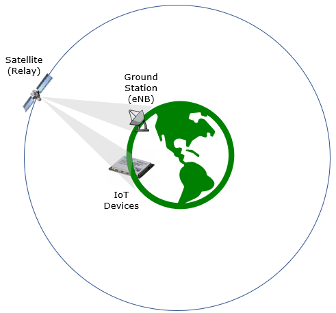
This last picture is deliberately minimal, and it is a good one to keep in mind as the mental default. A single satellite acting purely as a relay, a ground station that contains the actual base station, and terminals on the ground. Every other configuration on this page is a variation on it : move the base station up into the satellite and you get Scenario B/D; put a relay node between the terminals and the satellite and you get A3/A4; add links between satellites and you get ISL; let the beam slide instead of steering it and you get the Earth-moving variants.
3GPP Reference
- Non-Terrestrial Networks (NTN) - 3GPP Technology Article (2024)
- 3GPP TR 38.811 : Study on New Radio (NR) to support non-terrestrial networks
- 3GPP TR 38.821 : Solutions for NR to support non-terrestrial networks (NTN)
- 3GPP TR 38.913 : Study on scenarios and requirements for next generation access technologies
- 3GPP TR 23.737 - Study on architecture aspects for using satellite access in 5G
- RP-193234 : Solutions for NR to support non-terrestrial networks (NTN)
- TS 22.261 : Service requirements for the 5G system; Stage 1 (Release 18)
- 3GPP TS 38.101-5 : NR; User Equipment (UE) radio transmission and reception; Part 5: Satellite access Radio Frequency (RF) and performance requirements
- 3GPP TS 38.300 : NR and NG-RAN Overall Description - clause on NTN specifics
- 3GPP TS 38.401 : NG-RAN; Architecture description - gNB-CU / gNB-DU split and F1
- 3GPP TS 38.331 : NR; Radio Resource Control (RRC) protocol specification - SIB19 and NTN assistance information
- 3GPP TS 23.501 : System architecture for the 5G System (5GS) - N2 / N3 / N6 reference points
- 3GPP TR 36.763 : Study on Narrow-Band Internet of Things (NB-IoT) / enhanced Machine Type Communication (eMTC) support for Non-Terrestrial Networks (NTN)
Related Pages on this Site
- NTN - What is it ? - the end-to-end overview that this page assumes as background
- Why NTN ? - the motivation behind the deployment scenarios listed here
- NTN Spectrum - the FR1-NTN / FR2-NTN bands that the architecture options are actually deployed in
- NTN Requirement - delay and performance targets behind the numbers on this page
- NTN Challenges - what the delay, Doppler and mobility properties break
- NTN Timing Advance - how the differential delay across a beam is compensated
- NTN RACH - why the preamble receiving window has to be redesigned for NTN
- NTN RRC (NR) - SIB19 and the NTN specific RRC parameters
- NTN Call Flow (NR) - the architecture put in motion
Other References
- Non-terrestrial networks (NTN) - R&S
- Non-Terrestrial Network Advantages, Challenges, and Applications - Keysight
- 5G & Non-Terrestrial Networks - 5G Americas White Paper (2022)
- Orbit of a satellite Calculator
- LEO Small-Satellite Constellations for 5G and Beyond-5G Communications
- Satellite Communications in the New Space Era: A Survey and Future Challenges
- Assessing satellite-terrestrial integration opportunities in the 5G environment
- Satellite and Terrestrial Network for 5G
- Application of 5G new radio for satellite links with low peak-to-average power ratios
- 5G from Space: An Overview of 3GPP Non-Terrestrial Networks