Communiation through Satellites in NTN introduces significant challenges in timing and synchronization due to the large distances involved, which result in much longer propagation delays compared to terrestrial networks. For example, a satellite in geostationary orbit (GEO) at ~36,000 km altitude introduces a round-trip time (RTT) of about 240 ms, whereas terrestrial networks typically have RTTs of a few milliseconds.
In NTNs, the large distances and relative motion between the UE and the satellite introduce significant challenges in timing, synchronization, and frequency alignment. This section of the 3GPP specification ensures that the UE and network can communicate reliably by:
- Adjusting for propagation delays using offsets and Timing Advances.
- Managing HARQ processes to handle long RTTs.
- Pre-compensating for Doppler shifts to maintain frequency alignment.
This is critical for applications like satellite-based internet (e.g., Starlink), remote sensing, and global IoT connectivity, where NTNs are increasingly important.
The note addresses how to manage these delays to ensure proper communication between the UE (e.g., a smartphone or IoT device), the gNB (on the satellite), and the NTN gateway (on Earth), especially when the gNB and NTN gateway are co-located.
- Why Timing in NTN is a Different Problem
- Scheduling and Timing
- Reading the Timing Relationship Diagram
- The Timing Advance Equation
- Common TA, Drift and Validity
- Koffset and Kmac in Practice
- HARQ Operation
- Why HARQ Stalls in NTN - in Numbers
- Timing Advance and Frequency Pre-compensation
- Doppler in Numbers
- TA Lifecycle : Acquire, Apply, Maintain
- Worked Example : Where the 3GPP Numbers Come From
- Where the Numbers Live : SIB19 Parameters
- What Breaks When the Timing is Wrong
Why Timing in NTN is a Different Problem
It is tempting to think of NTN timing as 'terrestrial timing, but with bigger numbers'. It is not, and the reason is worth being precise about. Timing advance exists in LTE and NR too, so the mechanism is familiar - but in a terrestrial cell the delay is small, almost constant, and
|
Terrestrial macro cell |
LEO at 600 km |
GEO at 35,786 km |
|
|---|---|---|---|
|
Cell size (edge to edge) |
A few km up to a few tens of km |
Up to 1,000 km |
Up to 3,500 km |
|
Max round trip propagation delay |
Well under 1 ms |
12.89 ms regenerative / 25.77 ms transparent |
270.73 ms regenerative / 541.46 ms transparent |
|
Differential delay within one cell |
Fractions of a millisecond |
3.12 ms |
10.3 ms |
|
Where the relative motion comes from |
|
|
|
|
How fast the delay changes (round trip) |
Zero for a static UE; approx. 0.46 us/s at 250 km/h and approx. 0.93 us/s at 500 km/h - and only while the UE is moving directly towards or away from the site |
Up to +/- 93 us/s (transparent) or +/- 47.6 us/s (regenerative), |
Negligible from the satellite; the UE's own motion contributes the same order as the terrestrial column |
|
Max Doppler shift at 2 GHz |
0 Hz static; approx. 460 Hz at 250 km/h; approx. 930 Hz at 500 km/h (high-speed train). The total swing across a site pass is roughly twice that. |
24 ppm, i.e. approx. 48 kHz for a static UE - before any UE motion is added |
0.93 ppm, i.e. approx. 1.9 kHz for a static UE. A UE at 1200 km/h adds approx. 1.11 ppm on top - |
|
Who works out the initial TA |
The network, by measuring the preamble arrival time |
The UE itself, from GNSS position + broadcast ephemeris, |
Same as LEO |
-
Magnitude. A UE at 500 km/h has a relative velocity of 0.46 ppm of c. A LEO satellite at 600 km reaches 24 ppm. Even the fastest train is therefore around
fifty times below the LEO figure, and that is before remembering that in NTN the satellite's own motion is present in addition to whatever the UE is doing. At GEO the picture inverts : a UE at 1200 km/h (1.11 ppm) actually contributes more Doppler than the satellite's 0.93 ppm, so for GEO the terrestrial intuition about UE mobility is the right one. -
Ownership, and therefore predictability. In a terrestrial cell the motion belongs to the UE, so the network cannot predict it and the receiver has to track it closed-loop. In NTN the dominant motion belongs to the
platform , whose trajectory is known in advance and broadcast as ephemeris. That is precisely why open-loop pre-compensation is possible at all in NTN and is not a technique terrestrial NR ever needed.
There is one quantity where the terrestrial case is genuinely not the milder one, and it is worth stating so the comparison is honest. The Doppler rate of change peaks at closest approach, where it is approximately v2 fc / (d0 c) for a UE passing a site at distance d0. A train at 500 km/h passing within 50 m of a trackside site sees roughly 2.6 kHz/s at 2 GHz - several times the 540 Hz/s of a LEO pass, because the geometry changes far more abruptly at 50 m than at 600 km. Terrestrial receivers have therefore always coped with fast Doppler dynamics. What they have never had to cope with is a Doppler offset of tens of kilohertz that is already present in the very first sample, before synchronisation has started - and that, rather than the rate of change, is the specifically NTN problem.
Almost every NTN timing feature in the specification can be traced back to one of these three, and it is much easier to keep them straight than to treat 'delay' as a single issue :
-
1. The absolute delay is huge. This is a large, essentially common offset shared by everyone in the cell. It does not stop the radio link from working, but it breaks every protocol relationship that assumes a response arrives 'a few slots later' - scheduling offsets, response windows, MAC CE application timing and HARQ round trips. The answer is the Common TA plus the scheduling offsets Koffset and Kmac, and the option to stop relying on HARQ feedback altogether.
-
2. The delay is different for every UE in the cell. A UE at the centre of a 1,000 km footprint and one at its edge are milliseconds apart - far more than a cyclic prefix. A single common correction therefore cannot align everybody, which is why NTN keeps a UE-specific TA term on top of the common one, and why the UE has to compute its own before its first transmission. This is also the part that makes the RACH design hard - see NTN RACH.
-
3. In LEO, the delay will not sit still. At 7.56 km/s(linear speed of the satellite in 600km orbit as an example), the round trip time changes by tens of microseconds every second, so a TA value is not a setting - it is a trajectory. This is why the network broadcasts not just a common TA but its first and second derivatives (drift and drift variant), and why the assistance data comes with a validity duration after which it must be refreshed.
That figure is quoted in TR 38.821 Table 7.1-1 as the relative speed of the satellite with respect to the earth for the 600 km scenarios, but it is worth knowing that it is nothing more than the circular orbit velocity :
v = sqrt( μ / r ) = sqrt( 398,600 / 6,971 ) = 7.56 km/s
with μ = 398,600 km3/s2 the Earth's standard gravitational parameter, and r the orbital radius measured from the
For timing purposes what matters is not the full 7.56 km/s but its component
-
The range rate can never exceed the orbital speed itself, so the Doppler is hard-limited to 7.56 / 299,792 = 25.2 ppm. Nothing in a 600 km LEO system can be faster than that.
-
Geometrically the line-of-sight component maxes out at roughly v x Re / r near the horizon, i.e. around 23 ppm. TR 38.821 quotes 24 ppm for the reference scenario, comfortably inside the bracket.
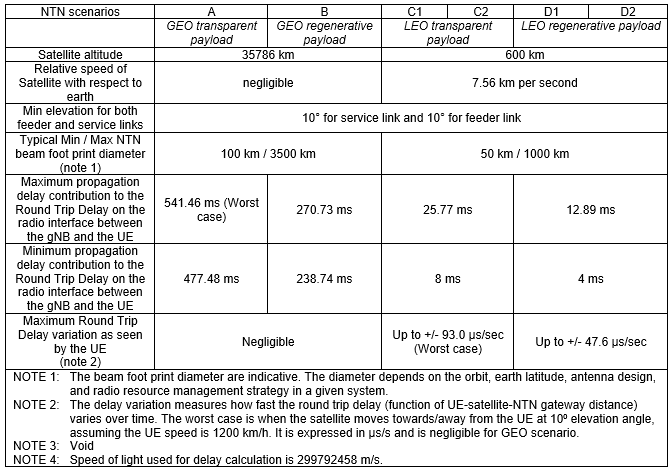
And that is where the 'tens of microseconds every second' in the bullet above comes from. A range rate of about 24 ppm means the one-way path length changes by about 24 us of propagation time per second, so the round trip delay drifts at roughly 48 us/s - which is exactly the +/- 47.6 us/s that Table 7.1-1 lists for the LEO regenerative scenarios. The Doppler row and the delay-variation row of that table are the same physical quantity written in two different units, as noted in Doppler in Numbers below.
All of the above is much easier to see than to describe. The three plots below are one complete LEO pass - the satellite rising at the horizon, going almost directly overhead, and setting again - with slant range, elevation angle and Doppler shift plotted against time from rise.
< Slant range, elevation angle and Doppler shift over one LEO pass >
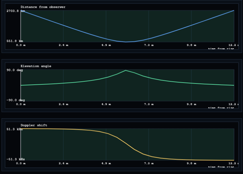
The single most important thing in this picture is that
-
Distance (top) starts at 2,703.8 km at the horizon, falls to 551.8 km at closest approach, and climbs back. In timing terms the round trip delay swings from about
18.0 ms down to 3.7 ms and back up - a 14.4 ms change, on the same link, with the same satellite, in about six minutes. No single TA value could possibly serve that pass, which is exactly why the assistance data is a polynomial with a validity duration rather than a number. -
Elevation (middle) rises from 0° to nearly 90° and back over 12.2 minutes. That is the whole visibility window for one satellite - and it is the practical reason a LEO cell has to be handed over every few minutes whether or not the UE ever moves.
-
Doppler (bottom) starts at its positive maximum of +51.3 kHz while the satellite is approaching, passes through
exactly zero at the moment of highest elevation , and ends at -51.3 kHz as the satellite recedes. The zero crossing lines up precisely with the minimum of the distance curve, because that is the instant the range stops shrinking and starts growing.
This particular pass is a useful worked example because every value in it can be reproduced from the formulas above. The 2,703.8 km maximum is the slant range at 0° elevation for a
-
The peak line-of-sight velocity is v x Re / r = 7.59 x 6,371 / 6,921 = 6.99 km/s, i.e. 23.3 ppm - right in the middle of the 23 to 25.2 ppm bracket derived above, and consistent with the 24 ppm that TR 38.821 quotes for its 600 km reference case.
-
Working backwards from the plot, a peak of 51.3 kHz at 23.3 ppm implies a carrier of about 2.2 GHz - S band, at the top of NTN band n256. Change the carrier and the top two plots stay exactly where they are while the bottom one scales linearly, which is a good way to convince yourself that Doppler is a frequency-domain restatement of the same geometry.
-
The corresponding round trip delay drift is 2 x 23.3 = 46.6 us/s at the horizon, against the +/- 47.6 us/s that Table 7.1-1 lists for LEO regenerative scenarios. The plot and the specification table are describing the same thing.
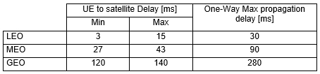
< TR38.811 - typical one-way propagation delay per orbit >
< TR38.821 v16.2.0-Table 7.1-1: Propagation delay and delay variation per NTN scenario >
Scheduling and Timing
In NTNs, scheduling and timing are critical due to the significant propagation delays introduced by long distances between UE and satellite-based gNBs. To maintain synchronization between downlink (DL) and uplink (UL) transmissions, frame alignment is achieved at the uplink time synchronization reference point (RP), with adjustments made using a configured offset. To address timing discrepancies and ensure accurate scheduling, the system incorporates a Common Timing Advance (Common TA) along with two additional timing offsets: K_offset and K_mac. These parameters collectively compensate for round-trip delays and allow sufficient processing time for the UE between DL reception and UL transmission. Furthermore, they facilitate proper coordination in procedures such as random access and MAC CE command handling, ensuring that frame alignment and resource scheduling remain robust despite the inherent latency of NTN environments.
Timing Advance and additional terminologies related to NTN Timing Adjustment are well summarized in the following diagram.
< 38.300 - Figure 16.14.2.1-1: Illustration of timing relationship (for collocated gNB and NTN Gateway) >
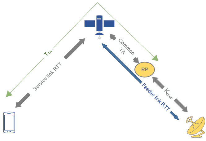
- Service Link RTT: The delay between the UE (on Earth) and the satellite.
- Feeder Link RTT: The delay between the satellite and the NTN gateway (on Earth).
- Common TA: The RTT between the RP and the NTN payload.
- TTA: The total timing advance, which includes the service link RTT and feeder link RTT.
- Kmac: The offset applied to account for the RTT between the RP and gNB.
Following is breakdown of each component on the diagram and its definition.
Uplink (UL) Frame Alignment and Timing Reference Point (RP): - The UE aligns its uplink (UL) frame timing with the reference point (RP) on the satellite (gNB), adjusted by an offset called NTA,offset. This offset accounts for the propagation delay between the UE and the satellite.
Propagation Delay in NTNs: - Due to the large distances in NTNs, the propagation delay is significant. To manage this, the system uses a Common Timing Advance (Common TA) and two offsets: Koffset and Kmac.
Timing Relationships: - Common TA: This is the round-trip time (RTT) between the RP (on the satellite) and the NTN payload (also on the satellite). Since the gNB and NTN gateway are co-located, this RTT represents the delay between the satellite and the ground gateway.
- Koffset: A scheduling offset that must be at least equal to the sum of the service link RTT (between UE and satellite) and the Common TA. It ensures the UE has enough time to process downlink receptions and uplink transmissions. (Must be >= RTT of Service Link + Common TA.)
- Kmac: Another offset, approximately equal to the RTT between the RP and the gNB (on the satellite). It allows the UE sufficient processing time for downlink and uplink tasks.
Practical Configuration: - The offset Koffset is used to give the UE enough time to process downlink data and prepare uplink transmissions.
- Kmac is used to determine the start of the Random Access Response (RAR) window or MsgB window after a Msg1/MsgA transmission (part of the random access procedure).
Is the RP a physical entity ?
This is the first question almost everyone asks about the diagram, and the answer is worth stating plainly :
The RP is a timing definition - the point at which uplink frame timing is defined to be aligned with downlink frame timing (offset by NTA,offset). TS 38.300 calls it the uplink time synchronization reference point and never ties it to any physical entity.
The detail that settles it is this :
|
What the network broadcasts as ta-Common |
Where that implicitly places the RP |
Typical deployment |
|---|---|---|
|
Zero, or the field is absent |
At the satellite (the NTN payload itself) |
Regenerative payload - the gNB is on board, so there is nothing beyond the satellite to account for |
|
The full feeder link round trip |
At the gateway / gNB on the ground |
Transparent payload - the case drawn in the figure above |
|
Some value in between |
A point somewhere along the feeder path - possibly with nothing physically there at all |
An implementation choice, e.g. to keep the broadcast value in a convenient range |
Notice how 3GPP drew it in the figure : the RP is a blob floating on the feeder link, deliberately
If you have ever calibrated a vector network analyser, you already know this concept. You calibrate to a reference plane that may sit in the middle of a cable where there is no connector, no component and nothing to point at - yet every measurement afterwards is expressed relative to it, and moving the plane changes all your numbers without changing a single piece of hardware. The RP is exactly that idea applied to timing instead of to S-parameters.
Because it decouples the specification from the deployment. Since the split between 'what the network broadcasts' and 'what the UE computes' is expressed relative to a movable reference rather than a named box,
The same diagram, with numbers
The terms above stay abstract until they are given values, so here is the whole figure filled in for three concrete deployments, using the worst-case (10° elevation) reference figures from TR 38.821 that appear elsewhere on this page. Every row is just the diagram read with a different RP placement and a different orbit.
|
Quantity in the figure |
GEO transparent |
LEO 600 km transparent |
LEO 600 km regenerative |
|---|---|---|---|
|
Service link RTT (UE <-> satellite) |
270.73 ms |
12.89 ms |
12.89 ms |
|
Feeder link RTT (satellite <-> gateway) |
270.73 ms |
12.89 ms |
Exists, but is |
|
Common TA (RP <-> NTN payload) |
270.73 ms - the whole feeder link |
12.89 ms |
|
|
TTA (what the UE actually applies) |
541.46 ms |
25.77 ms |
12.89 ms |
|
Kmac (RP <-> gNB) |
0 - gNB and gateway are collocated at the RP |
0, for the same reason |
0 - the gNB is at the RP, on board |
|
Minimum Koffset (service link RTT + Common TA) |
541.46 ms, so at least 542 slots at 15 kHz |
25.77 ms, so at least 26 slots |
12.89 ms, so at least 13 slots |
Three things become obvious once the diagram carries numbers rather than labels :
-
TTA is not the same as the service link RTT. In the transparent columns it is twice as large, because the UE is compensating for a feeder link it cannot see and knows nothing about. This is the single most common misreading of the figure.
-
Moving the RP moves work between the two parties, not out of the system. Compare the two LEO columns : the regenerative case has a Common TA of zero, but the feeder link has not vanished - it has simply been placed outside the UE's timing loop, where the network deals with it alone.
-
Kmac is zero in all three columns, because all three assume the gNB sits at the RP. It only becomes non-zero in the case the figure's caption explicitly excludes - a gNB that is not collocated with the gateway, for instance one gNB serving several gateways over terrestrial transport.
Reading the Timing Relationship Diagram
The 38.300 figure above repays a slow reading, because almost every NTN timing term is defined by
The yellow ellipse marked RP sits on the feeder link, between the satellite and the gateway, and it is the single most misunderstood object in the diagram. It is not a piece of equipment. It is a
-
Service link RTT spans UE <-> satellite. The UE has to work this one out for itself, because only the UE knows where it is.
-
Common TA spans RP <-> NTN payload. This is the part every UE in the cell shares, so the network can simply broadcast it.
-
Feeder link RTT spans satellite <-> gateway. Part of it is inside the Common TA and part of it is beyond the RP, depending on where the RP is placed.
-
Kmac spans RP <-> gNB. In the figure the gNB and the gateway are collocated, which is why this arrow ends at the dish.
-
TTA is the green outer span - the total advance the UE actually applies to its transmitter.
Because the RP is a definition rather than a device, the operator gets to choose where it sits, and that choice decides how the total delay is split between the part the network broadcasts and the part the UE computes. The total is of course the same either way - only the bookkeeping changes.
|
RP placed at ... |
Common TA broadcast in SIB19 |
What the UE has to compute itself |
Typical case |
|---|---|---|---|
|
The satellite (NTN payload) |
Zero (the field can be absent) |
The service link only |
Regenerative payload - the gNB is on board, so there is nothing beyond the satellite to compensate for |
|
The gateway / gNB on the ground |
The full feeder link round trip |
The service link only |
Transparent payload - the classic bent-pipe case, and the one drawn in the figure |
|
Somewhere on the feeder link |
The portion between RP and satellite |
The service link only |
An implementation choice, e.g. to keep the broadcast value inside a convenient range |
The figure's caption says 'for collocated gNB and NTN Gateway', and that qualifier matters. If the gNB is
The Timing Advance Equation
All of the above collapses into a single expression. The uplink transmit timing advance that the UE applies is :
TTA = ( NTA + NTA,offset + NTA,adjcommon + NTA,adjUE ) x Tc
where Tc is the NR basic time unit (approximately 0.509 ns). The interesting thing about this expression is not the arithmetic but
|
Term |
Who determines it |
What it covers |
Exists in terrestrial NR ? |
|---|---|---|---|
|
NTA |
Network - Timing Advance Command in the RAR, then TA Command MAC CE |
The closed-loop residual : whatever the UE's own estimate got wrong |
Yes |
|
NTA,offset |
Fixed per band, or signalled as n-TimingAdvanceOffset |
The Tx/Rx switching margin of the duplex arrangement - nothing to do with distance |
Yes |
|
NTA,adjcommon |
Network - derived from ta-Common, ta-CommonDrift and ta-CommonDriftVariant in SIB19 |
RP <-> satellite : the part of the delay that is the same for the whole cell |
No - NTN only |
|
NTA,adjUE |
The UE itself, from its GNSS position and the broadcast ephemeris |
UE <-> satellite : the service link, which is different for every UE |
No - NTN only |
A natural question is how a 12-bit Timing Advance Command in the RAR can possibly express a 541 ms round trip. The answer is that
The reverse direction is worth knowing too. Because the network no longer measures the full delay, it also no longer knows it. When ta-Report is enabled in SIB19, the UE reports the TA it actually applied during random access, which lets the network reconstruct the absolute delay - useful for scheduling accuracy and for network-verified UE location.
Common TA, Drift and Validity
In a GEO system the Common TA is close to a constant and could almost be a static configuration value. In LEO it is not - the feeder link geometry changes continuously as the satellite crosses the sky, so a single broadcast number would be stale within a second or two. Rel-17 solves this by broadcasting the value
|
SIB19 field |
ASN.1 range |
Granularity |
Full scale |
Role |
|---|---|---|---|---|
|
ta-Common |
INTEGER (0..66485757) |
4.072 x 10⁻³ us |
approx. 270.73 ms |
Constant term - the Common TA at the epoch instant |
|
ta-CommonDrift |
INTEGER (-257303..257303) |
0.2 x 10⁻³ us/s |
approx. +/- 51.5 us/s |
First-order term - how fast the Common TA is changing. Signed, because the satellite can be approaching or receding. |
|
ta-CommonDriftVariant |
INTEGER (0..28949) |
0.2 x 10⁻⁴ us/s2 |
approx. 0.58 us/s2 |
Second-order term - how fast the drift itself is changing, which is what keeps the extrapolation accurate across a whole pass |
|
epochTime |
SFN 0..1023, subframe 0..9 |
1 subframe |
- |
The instant the constant, drift and ephemeris values refer to. Without it the polynomial has no origin. |
|
ntn-ULSyncValidityDuration |
s5 ... s60, s120, s180, s240, s900 |
seconds |
up to 900 s |
How long the UE may keep extrapolating from epochTime before it must re-acquire the assistance data |
The UE reconstructs the Common TA at any instant as a second-order polynomial in the time elapsed since epochTime : the constant term ta-Common, plus the first-order term ta-CommonDrift, plus the second-order term ta-CommonDriftVariant. It does the same kind of extrapolation on the satellite ephemeris (either the Cartesian position/velocity state vectors or the orbital elements) to work out its own service link contribution.
These field ranges look arbitrary until you multiply them out, at which point it becomes clear they were sized directly from the TR 38.821 reference scenarios :
-
66,485,757 x 4.072 x 10-3 us =
270,730 us = 270.73 ms . That is exactly the maximum round trip delay of Scenario B in the reference table - the worst-case GEO one-hop figure. The field is sized to hold the worst GEO case and not one bit more. -
257,303 x 0.2 x 10-3 us/s =
+/- 51.5 us/s , which comfortably covers the +/- 47.6 us/s worst-case delay variation quoted for the LEO regenerative scenarios in Table 7.1-1.
ntn-ULSyncValidityDuration is what stops a UE from transmitting on the basis of stale geometry. Once it expires, the UE is no longer allowed to consider itself uplink-synchronised and must re-acquire the assistance data before transmitting again. The wide enumeration range is a direct reflection of the orbit : a few seconds is appropriate for a fast LEO pass where the geometry is changing every moment, while the 900 s value only makes sense for a GEO system where almost nothing moves. Reading this one value off a live SIB19 tells you a great deal about what kind of system you are looking at.
Koffset and Kmac in Practice
Timing advance solves the problem of signals arriving at the right moment. It does not solve a second, subtler problem :
In terrestrial NR, a UE that receives an uplink grant in slot n transmits in slot n+K2. The UE also advances its transmitter by TTA, but TTA is a fraction of a slot, so nothing dramatic happens. Now make TTA several hundred milliseconds. Slot n+K2 measured on the UE's advanced transmit timeline can land
Koffset pushes every such uplink relationship far enough into the future to restore causality. This is why the original requirement above is stated the way it is : Koffset must be at least the service link RTT plus the Common TA - in other words at least as large as the advance the UE is applying.
|
cellSpecificKoffset (Koffset) |
kmac (Kmac) |
|
|---|---|---|
|
ASN.1 range |
INTEGER (1..1023) |
INTEGER (1..512) |
|
Unit |
Slots at 15 kHz SCS, i.e. 1 ms per step |
Slots at 15 kHz SCS (FR1) |
|
Full scale |
approx. 1,023 ms |
approx. 512 ms |
|
If the field is absent |
The UE assumes 0 |
The UE assumes 0 |
|
What it shifts |
Uplink scheduling relationships - the grant-to-PUSCH offset, the PDSCH-to-HARQ-ACK offset, the RAR grant timing, aperiodic SRS and CSI, configured grants |
The instant at which a MAC CE action takes effect |
|
Problem it solves |
The UE transmits far ahead of its own downlink, so uplink timing relationships would otherwise be non-causal |
Downlink and uplink frame timing are not aligned at the gNB, so 'when does this command take effect' becomes ambiguous |
1,023 slots at 15 kHz is 1,023 ms, comfortably more than the 541.46 ms worst-case round trip of GEO Scenario A. Once again the field was sized against the reference scenario table rather than chosen for convenience - a useful habit to assume when a Rel-17 NTN range looks oddly specific.
HARQ (Hybrid Automatic Repeat Request) Operation
HARQ is a mechanism used in wireless communication to ensure reliable data transmission by combining error correction and retransmission. In NTNs, the large RTT complicates HARQ operation, so the document specifies how to configure it:
Downlink HARQ: - HARQ feedback (ACK or NACK) can be enabled or disabled per HARQ process.
- Disabling HARQ feedback is allowed if the RTT since the last scheduled HARQ process exceeds a certain time limit
Uplink HARQ: - Two modes are defined: HARQ mode A and HARQ mode B.
- These modes can be configured per HARQ process
HARQ mode B allows scheduling a HARQ process before the RTT of the previous HARQ process has elapsed, which helps manage the long delays in NTNs.Configuration Flexibility: - Whether HARQ feedback is enabled or disabled, the network decides the configuration.
- For processes with HARQ feedback enabled, the network can choose between enabling or disabling all HARQ processes.
- For processes with a specific HARQ mode, the network can choose between HARQ mode A or HARQ mode B.
Why HARQ Stalls in NTN - in Numbers
The statement that 'HARQ has trouble with long RTTs' is easy to accept and easy to under-estimate. It is worth putting numbers on it, because the numbers explain why 3GPP did something as drastic as allowing HARQ feedback to be switched off.
HARQ is stop-and-wait
( number of HARQ processes ) x ( slot duration ) >= HARQ round trip time
Everything above that limit is dead air. At 15 kHz subcarrier spacing a slot is 1 ms, so the number of HARQ processes is, conveniently, roughly the number of milliseconds of round trip the pipeline can absorb. Rel-15 NR gives 16 PDSCH HARQ processes; Rel-17 raises this to 32 for NTN via nrofHARQ-ProcessesForPDSCH-v1700. Against the reference scenarios that buys :
|
Scenario |
Max round trip delay |
Processes needed at 15 kHz SCS (before processing time) |
Can 32 processes keep the pipe full ? |
|---|---|---|---|
|
D (LEO 600 km, regenerative) |
12.89 ms |
approx. 13 |
Yes - even the legacy 16 is enough |
|
D (LEO 1200 km, regenerative) |
20.89 ms |
approx. 21 |
Yes, but only because Rel-17 raised the count to 32 |
|
C (LEO 600 km, transparent) |
25.77 ms |
approx. 26 |
Just barely, with no margin for processing |
|
C (LEO 1200 km, transparent) |
41.77 ms |
approx. 42 |
No |
|
B (GEO, regenerative) |
270.73 ms |
approx. 271 |
Not remotely |
|
A (GEO, transparent) |
541.46 ms |
approx. 542 |
Not remotely |
Two conclusions fall straight out of this table. First,
|
HARQ feedback enabled |
HARQ feedback disabled |
|
|---|---|---|
|
Process reuse |
Blocked until the ACK/NACK returns |
Immediate - the process is never waiting for anything |
|
Who recovers a lost block |
HARQ, quickly, with soft combining |
RLC AM, over a much slower loop and with no soft combining |
|
Link adaptation |
Can be aggressive - a first-attempt error is cheap to fix |
Must be conservative, or use blind repetition, because a first-attempt error is expensive |
|
Best suited to |
Short-RTT NTN - LEO, and especially regenerative LEO |
Long-RTT NTN - GEO, and any case where throughput matters more than a fast first-attempt fix |
Timing Advance and Frequency Pre-compensation
In NTNs, precise timing and frequency control are essential to counteract the large delays and Doppler effects caused by the high-altitude movement of satellites. Timing Advance and Frequency Pre-compensation mechanisms are employed to maintain uplink synchronization and signal integrity. Before establishing a connection to an NTN cell, the UE must possess a valid GNSS position along with ephemeris data and a configured Common Timing Advance. Using this information, the UE calculates the round-trip time between itself and the uplink reference point (RP) and applies a pre-compensation value, T_TA, to align its uplink transmissions. Additionally, the UE autonomously estimates the Doppler shift on the service link and adjusts its transmission frequency accordingly. These procedures ensure that uplink signals arrive at the gNB within the expected timing and frequency windows, which is vital for maintaining reliable communication in the dynamic NTN environment.
Timing Advance (TA) for Synchronization
- The UE needs to synchronize with the NTN cell using GNSS (Global Navigation Satellite System) position, ephemeris data (satellite position and velocity), and Common TA parameters.
- The UE calculates the RTT between itself and the RP (on the satellite) and pre-compensates the Timing Advance (TTA) for this RTT.
- The UE also computes the frequency Doppler shift (due to the relative motion between the UE and the satellite) and pre-compensates for it in uplink transmissions.
- If the UE lacks a valid GNSS position or ephemeris data, it cannot pre-compensate, and the Timing Advance and frequency pre-compensation must be updated in connected mode (i.e., while the UE is actively communicating with the network).
Doppler Shift Management
- Doppler shift occurs because the satellite is moving relative to the UE, causing a frequency shift in the received signal.
- The UE pre-compensates for the Doppler shift on the service link (UE to satellite).
- Doppler shift on the feeder link (satellite to NTN gateway) and any transponder frequency errors are managed by the network, not the UE.
Doppler in Numbers
The Doppler shift is simply fd = (vrel / c) x fc, so the ppm figures quoted in the reference scenarios convert directly into hertz once a carrier frequency is chosen. Doing that conversion makes it obvious why pre-compensation is not optional.
|
Scenario (static UE) |
Max Doppler |
At 2 GHz (S band) |
At 30 GHz (Ka band UL) |
Rate of change at 2 GHz |
|---|---|---|---|---|
|
LEO 600 km |
24 ppm |
approx. 48 kHz |
approx. 720 kHz |
0.27 ppm/s, i.e. approx. 540 Hz/s |
|
LEO 1200 km |
21 ppm |
approx. 42 kHz |
approx. 630 kHz |
0.43 ppm/s, i.e. approx. 860 Hz/s |
|
GEO |
0.93 ppm |
approx. 1.9 kHz |
approx. 28 kHz |
0.000045 ppm/s - effectively static |
Now compare 48 kHz against a 15 kHz subcarrier spacing. Initial synchronisation on PSS/SSS can normally pull in a frequency error of roughly half a subcarrier spacing - a few kilohertz. A LEO Doppler shift at S band is
-
The UE compensates the service link. It can, because it knows its own GNSS position and the satellite's position and velocity from the broadcast ephemeris - which is exactly the information needed to compute vrel.
-
The network compensates the feeder link and any transponder frequency error. It must, because the UE has no idea where the gateway is, how the feeder link is routed, or what the payload's local oscillator is doing. This mirrors the timing split precisely : the UE owns the service link, the network owns everything beyond the satellite.
It is worth noticing that the Doppler figure in ppm and the round trip delay drift in us/s are not two independent facts about the system - they are the same quantity in two domains. A relative velocity of 24 ppm of c means the one-way path length changes by 24 us of propagation time every second, so the round trip delay changes by about 48 us/s. Compare that with the +/- 47.6 us/s delay variation quoted for the LEO regenerative scenarios in Table 7.1-1, and with the +/- 93 us/s quoted for the transparent ones (where a second moving link is in the loop). The numbers line up because they were never separate measurements :
round trip delay drift [us/s] ≈ 2 x Doppler [ppm] (per moving link)
This is a handy cross-check when reading NTN documents. If a paper quotes a Doppler figure and a delay-drift figure that do not satisfy this relationship to within a factor of two, one of them is describing a different link than you think. The pass plots earlier on this page show the relationship directly - the Doppler trace is literally the slope of the slant range trace.
Summary :
- Timing in NTNs:
- NTNs have large propagation delays due to the distance between the UE, satellite, and NTN gateway.
- The system uses offsets like Koffset, Kmac, and Common TA to manage these delays and ensure proper scheduling and synchronization.
- HARQ in NTNs:
- HARQ feedback can be enabled or disabled to handle long RTTs.
- Two HARQ modes (A and B) provide flexibility in scheduling retransmissions.
- Timing Advance and Doppler Compensation:
- The UE uses GNSS and ephemeris data to calculate the RTT and Doppler shift, pre-compensating for both to ensure accurate uplink timing and frequency alignment.
- The network handles Doppler shift on the feeder link.
TA Lifecycle : Acquire, Apply, Maintain
The individual mechanisms above are easier to hold together if they are laid out in the order a UE actually meets them. The single most important structural difference from terrestrial NR is at step 2 :
|
Phase |
What happens |
What it depends on |
If it is missing |
|---|---|---|---|
|
1. Before camping |
The UE acquires SIB19 (ephemeris, ta-Common and its drift terms, epochTime, validity duration) and obtains a GNSS position fix |
A working GNSS receiver and a readable SIB19 |
The UE is not permitted to access the NTN cell at all |
|
2. Before Msg1 / MsgA |
The UE computes NTA,adjUE from its own position and the satellite's, extrapolates NTA,adjcommon from the polynomial, and applies the total TTA - and the matching frequency pre-compensation |
Everything from phase 1, still inside its validity window |
The preamble arrives outside the gNB's receive window and random access simply never completes |
|
3. During random access |
The network corrects the residual error and eventually learns the UE-specific TA |
The RAR / MsgB timing advance command, and ta-Report if enabled |
The network has to keep scheduling on worst-case assumptions, wasting resources |
|
4. In connected mode |
The UE keeps updating its open-loop terms as the satellite moves; the network trims the residual with TA Command MAC CEs |
Fresh ephemeris and drift terms before ntn-ULSyncValidityDuration expires |
The UE must stop transmitting until it re-acquires the assistance data |
|
5. At cell / satellite change |
A different satellite means different ephemeris and a different Common TA, so the whole open-loop calculation restarts |
Neighbour cell assistance (ntn-NeighCellConfigList) broadcast in advance |
The UE would have to re-acquire everything after the switch, adding a gap to a handover that was otherwise perfectly predictable |
TR 38.821 illustrates the TA part of phase 3 for both procedures. These two figures are worth looking at side by side purely from the timing-advance point of view - the full random access story, including the preamble receiving window and the overlapping RACH occasion problem, is covered separately in NTN RACH.
<TR 38.821 - Figure 7.2.1.1.1.2-9: Framework on 4-step random access procedure for UE with location information >
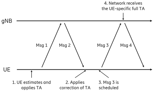
Read this one as a sequence of who knows the TA. At step 1 only the UE knows, and only approximately. At step 2 the network has measured the arrival of Msg1 and can send back a correction, but it still does not know the absolute value the UE started from. At step 3 the network has to schedule Msg3 while that ambiguity is still open, which is why it must assume the worst case delay in the cell. Only at step 4, once Msg3 has arrived, do both ends hold the same UE-specific TA.
<TR 38.821 - Figure 7.2.1.1.2-2: Framework on 2-step random access procedure for UE with location information >
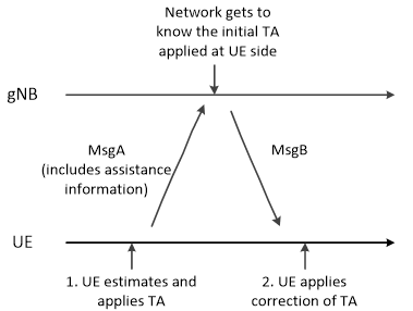
The 2-step version collapses that gap almost entirely. Because MsgA carries a PUSCH payload as well as a preamble, the UE can
Worked Example : Where the 3GPP Numbers Come From
All the delay figures quoted in TR 38.821 come from one piece of geometry, and reproducing it is the quickest way to stop treating those numbers as magic. For a circular orbit of altitude h seen at elevation angle e from a point on the Earth's surface, the slant range is
d = sqrt( (Re sin e)2 + 2 Re h + h2 ) - Re sin e
with Re = 6,371 km, and the one-way propagation delay is d / c using c = 299,792,458 m/s (the exact value TR 38.821 states it used). Running that for the reference altitudes :
|
Orbit |
Elevation |
Slant range |
Round trip, service link only (regenerative) |
Round trip, both links (transparent) |
|---|---|---|---|---|
|
LEO 600 km |
90� (overhead) |
600 km |
4.00 ms |
8.01 ms |
|
LEO 600 km |
30� |
1,075 km |
7.17 ms |
14.35 ms |
|
LEO 600 km |
10� (the specified minimum) |
|
|
|
|
GEO 35,786 km |
90� |
35,786 km |
|
|
|
GEO 35,786 km |
10� |
|
|
|
Every highlighted value is exactly what appears in the TR 38.821 reference tables - 1,932 km, 40,581 km, 12.89 / 25.77 ms, 238.74 / 270.73 ms and 477.48 / 541.46 ms. Three things fall out of this that are easy to miss when the numbers are just read off a table :
-
The 'maximum' delays are all the 10� case. The minimum elevation angle is not a coverage parameter that happens to be in the table - it is what defines the worst-case delay, and therefore what every timing field range was sized against. Lower the minimum elevation and every number in this page moves.
-
The transparent column is exactly twice the regenerative one, because the reference scenarios assume a feeder link of the same length as the worst-case service link. Real systems differ, which is why Common TA is signalled rather than derived.
-
The spread within one LEO pass is enormous : 4.00 ms overhead versus 12.89 ms at the horizon, i.e. nearly 9 ms of variation on the same link with the same satellite. That is the number the UE's open-loop tracking has to follow continuously.
That 9 ms figure is the spread across the satellite's entire field of view, and it is worth not confusing it with the 3.12 ms 'maximum differential delay within a cell' quoted in the reference table. A cell is one beam footprint - up to about 1,000 km for LEO - not the whole visible area, so the delay spread that a single cell's RACH design has to absorb is the smaller number. Both matter, but for different things : the field-of-view spread drives how fast the UE's open-loop estimate must track, while the within-cell spread drives the RACH and scheduling design.
Even that smaller number is brutal in radio terms. A normal cyclic prefix at 15 kHz subcarrier spacing is about 4.7 us. A 3.12 ms differential delay is therefore roughly
Where the Numbers Live : SIB19 Parameters
Everything discussed on this page is signalled through SIB19 and its ntn-Config, so it is useful to have the mapping from concept to field in one place. The ASN.1 detail and the surrounding RRC structures are covered in NTN RRC (NR).
|
Concept on this page |
Field |
Range / values |
Comment |
|---|---|---|---|
|
Common TA (constant term) |
ta-Common-r17 |
0..66485757 |
Full scale approx. 270.73 ms - the GEO worst case |
|
Common TA rate of change |
ta-CommonDrift-r17 |
-257303..257303 |
Signed - the satellite may be approaching or receding |
|
Second-order correction |
ta-CommonDriftVariant-r17 |
0..28949 |
Keeps the extrapolation valid over a longer window |
|
Time origin for all of the above |
epochTime-r17 |
SFN 0..1023, subframe 0..9 |
Also the origin for the ephemeris extrapolation |
|
How long the assistance stays usable |
ntn-ULSyncValidityDuration-r17 |
s5 ... s60, s120, s180, s240, s900 |
Short values imply LEO, long values imply GEO |
|
Satellite position and velocity |
ephemerisInfo-r17 |
PositionVelocity-r17 or Orbital-r17 |
Either Cartesian state vectors or classical orbital elements - the network chooses |
|
Uplink scheduling offset |
cellSpecificKoffset-r17 |
1..1023 slots at 15 kHz |
Dimensioned for the worst UE in the beam; absent means 0 |
|
MAC CE application offset |
kmac-r17 |
1..512 slots at 15 kHz |
Only when DL and UL frame timing are not aligned at the gNB |
|
UE reports the TA it applied |
ta-Report-r17 |
enabled |
Lets the network reconstruct the absolute delay it no longer measures |
|
Tx/Rx switching margin |
n-TimingAdvanceOffset |
Per band |
The NTA,offset term - inherited from terrestrial NR, nothing to do with distance |
|
HARQ adaptation |
downlinkHARQ-FeedbackDisabled-r17, nrofHARQ-ProcessesForPDSCH-v1700, DL-DataToUL-ACK-v1700 |
up to 32 processes |
Per-process feedback disabling plus NTN-specific PDSCH-to-HARQ-ACK timing |
|
Assistance for the next cell |
ntn-NeighCellConfigList-r17 |
Per neighbour |
Lets the UE pre-compute timing for a satellite it has not switched to yet |
|
When this cell stops serving the area |
t-Service-r17 |
Absolute time |
The quasi-Earth-fixed cell's expiry - the trigger for a planned, rather than measured, switch |
What Breaks When the Timing is Wrong
Timing faults in NTN rarely announce themselves as timing faults. They show up as a link that does not come up, or one that comes up and then quietly dies a minute later. The table below maps the common symptoms back to the mechanism responsible, which is usually the fastest way into a log.
|
Symptom |
Likely cause |
Where to look |
|---|---|---|
|
Cell is never found even though the signal level looks fine |
No Doppler pre-compensation - the frequency error is several subcarriers wide and initial synchronisation cannot pull it in |
GNSS fix validity, ephemeris freshness, carrier frequency |
|
Preambles are sent but no RAR ever comes back |
TTA wrong at phase 2 - the preamble lands outside the gNB's receive window |
ta-Common and drift terms, epochTime, the UE's own position |
|
RACH completes but Msg3 or the first data transfer fails |
Koffset too small - the uplink schedule is non-causal for this UE |
cellSpecificKoffset against the actual service link RTT plus Common TA |
|
Works near the middle of the beam, fails at the edge |
Differential delay across the footprint not fully covered |
Whether Koffset was dimensioned for the real footprint, and the RACH configuration |
|
Connection works for tens of seconds then drops, repeatedly |
ntn-ULSyncValidityDuration expiring without fresh assistance, or the drift terms not being applied |
SIB19 refresh period versus the configured validity duration |
|
Link is stable and error-free but throughput is far below expectation |
HARQ stall - not a radio problem at all. The process count cannot cover the round trip. |
Number of HARQ processes versus RTT, and whether feedback disabling is configured |
|
MAC CE commands appear to take effect at the wrong moment |
Kmac missing or wrong while DL and UL frame timing are not aligned at the gNB |
kmac, and where the RP has been placed relative to the gNB |
|
Everything works until the satellite changes, then a long gap |
Neighbour assistance not broadcast, so the UE restarts the whole open-loop calculation after the switch |
ntn-NeighCellConfigList, t-Service, and the handover configuration |
3GPP Reference
- Non-Terrestrial Networks (NTN) - 3GPP Technology Article (2024)
- 3GPP TR 38.811 : Study on New Radio (NR) to support non-terrestrial networks
- 3GPP TR 38.821 : Solutions for NR to support non-terrestrial networks (NTN)
- 3GPP TR 38.913 : Study on scenarios and requirements for next generation access technologies
- 3GPP TR 23.737 - Study on architecture aspects for using satellite access in 5G
- RP-193234 : Solutions for NR to support non-terrestrial networks (NTN)
- TS 22.261 : Service requirements for the 5G system; Stage 1 (Release 18)
- 3GPP TS 38.300 : NR and NG-RAN Overall Description - clause 16.14, the source of the timing relationship figure on this page
- 3GPP TS 38.213 : NR; Physical layer procedures for control - clause 4.2, the TTA expression, Koffset and Kmac
- 3GPP TS 38.331 : NR; Radio Resource Control (RRC) protocol specification - SIB19, ntn-Config, TAInfo, EphemerisInfo
- 3GPP TS 38.321 : NR; Medium Access Control (MAC) protocol specification - Timing Advance Command MAC CE, HARQ feedback disabling
- 3GPP TS 38.211 : NR; Physical channels and modulation - the basic time unit Tc and cyclic prefix lengths
- 3GPP TS 38.101-5 : NR; UE radio transmission and reception; Part 5: Satellite access - UE frequency error and timing requirements over NTN
- 3GPP TR 36.763 : Study on NB-IoT / eMTC support for Non-Terrestrial Networks - the IoT-NTN counterpart of the timing work described here
Related Pages on this Site
- NTN Architecture - why a transparent payload doubles every number on this page
- NTN RACH - the preamble receiving window, overlapping RACH occasions, and the full 4-step / 2-step procedures
- NTN RRC (NR) - the SIB19 and ntn-Config ASN.1 behind every parameter listed above
- NTN Requirement - the delay and performance targets the timing design has to meet
- NTN Challenges - timing seen alongside the other NTN problems
- NTN Call Flow (NR) - the TA lifecycle as it appears in an actual log
- Web Simulator : 2D Satellite Orbit, Doppler, Distance and Elevation - vary the altitude, pass geometry and carrier and watch slant range, elevation and Doppler respond together
- Web Simulator : Doppler Effect and Propagation Delay - the underlying relationship on its own, without the orbital geometry
Other References
- Non-terrestrial networks (NTN) - R&S
- Non-Terrestrial Network Advantages, Challenges, and Applications - Keysight
- 5G & Non-Terrestrial Networks - 5G Americas White Paper (2022)
- Orbit of a satellite Calculator
- LEO Small-Satellite Constellations for 5G and Beyond-5G Communications
- Satellite Communications in the New Space Era: A Survey and Future Challenges
- Assessing satellite-terrestrial integration opportunities in the 5G environment
- Satellite and Terrestrial Network for 5G
- Application of 5G new radio for satellite links with low peak-to-average power ratios
- 5G from Space: An Overview of 3GPP Non-Terrestrial Networks