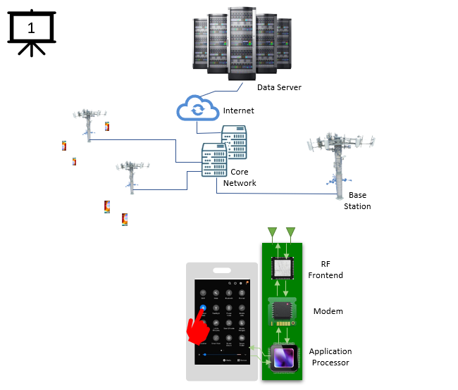
At first I made this slide show(anitmation) to exaplain what I am doing to other person who does not know anything about mobile communication. What I thought was 'If you don't know anything about mobile communication, you would have a mobile phone and you would have seen cell towers around you. so if I put the mobile phone and cell tower at the center and put other components around them and show
what would happen when you power on the phone, they would have at least some big picture about how the mobile communication works'. However, I think this can be used for anybody including experts in the field. I just depend on how much in detail you can describe on each slides. I have an animation with 66 slides. You can explain this animation in several tens of lines mainly for non experts but explain in several hundreds of pages if you go really deep into details.
Here, I will just go with super high level description with just around 30 lines. If you are new this area, I would recommend you to go through the high level description here without clicking into the linked page since you would be overwhelmed. But if you are already in this area or plan to work in this field, click into the details and try to learn further.
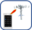
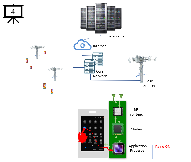
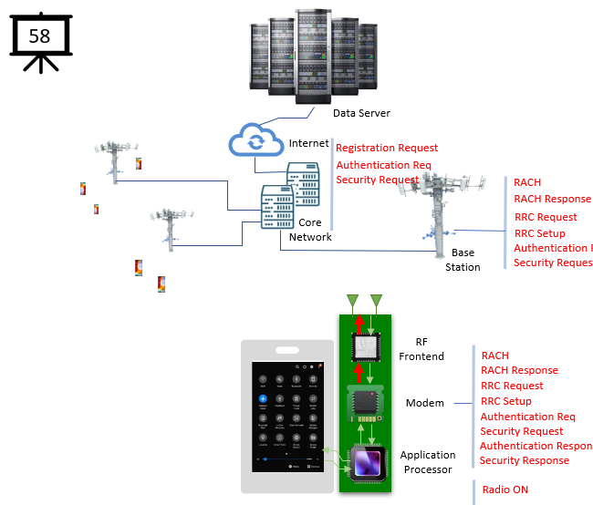
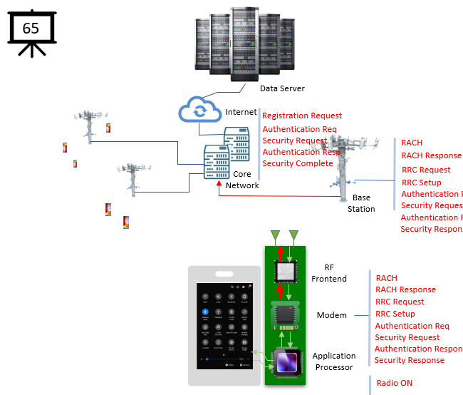
[1] Press Power On (or Airplane mode off) button on UE(User Equipment, e.g, mobile phone) display
[2]-[3] The Power On signal goes to Application Processor (AP)
[4] The signal is translated (recognized) as 'Radio ON' command in AP chip
[5]-[6] The 'Radio On' command is transferred to Modem chip (MODEM).
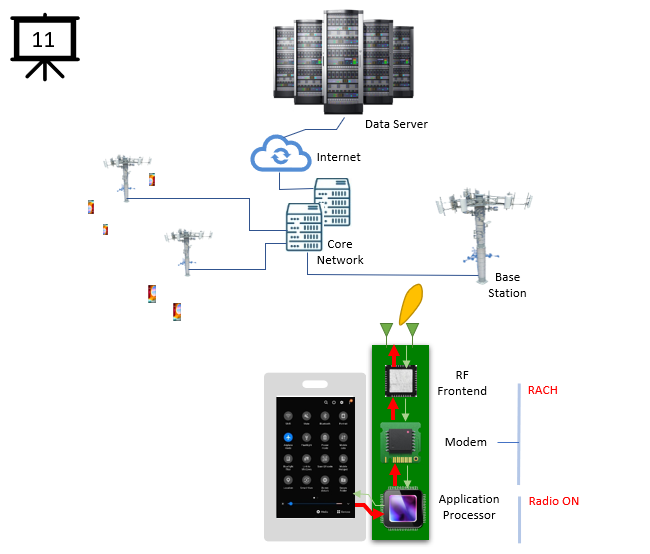
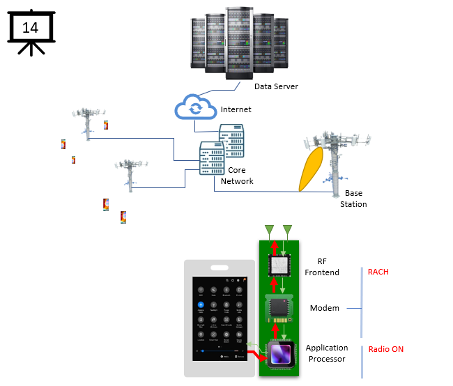
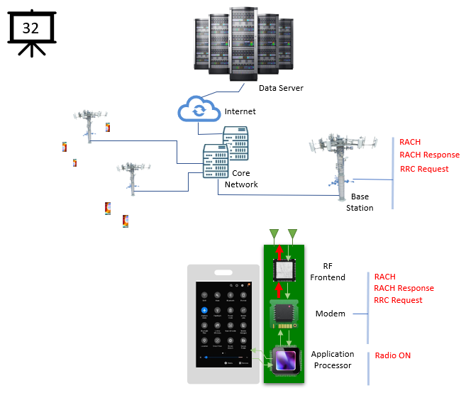
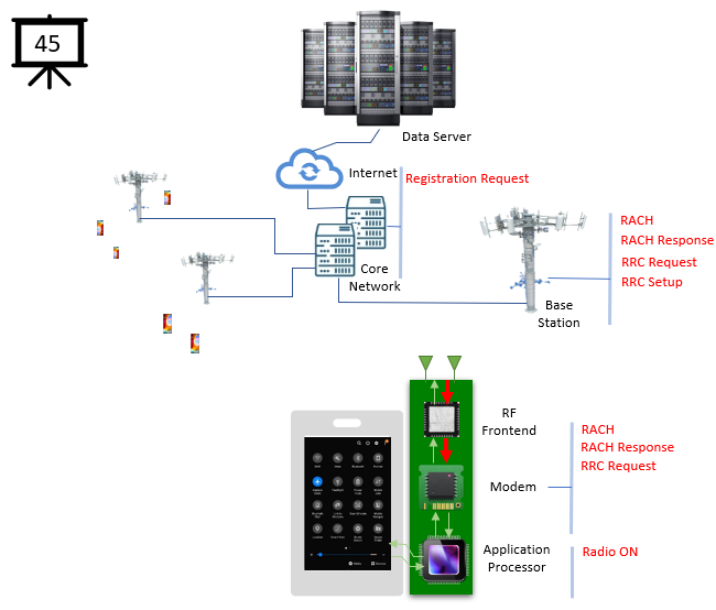
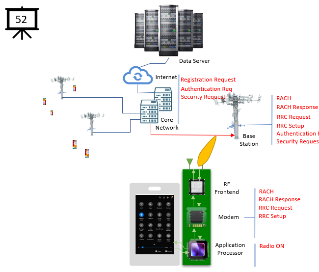
[7] Once the modem chip recieves the 'Power ON' command, it performs a sequence of internal procedure and initiate 'RACH' process
NOTE : If you are interested in more technical knowledge about this, check this out.
NOTE : If this is 5G system, additional step (e.g, Beam Detection) happens as explained here and here.
NOTE : If you want to know further about RACH signal, check this(4G) and this(5G) out.
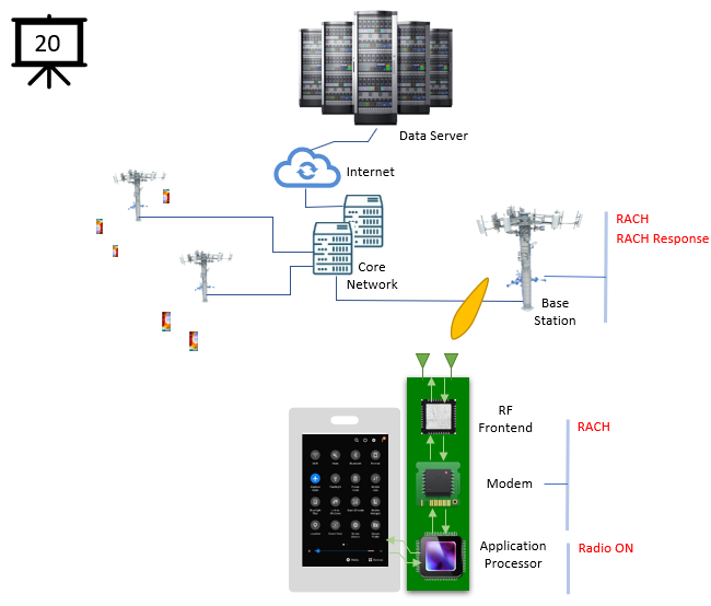
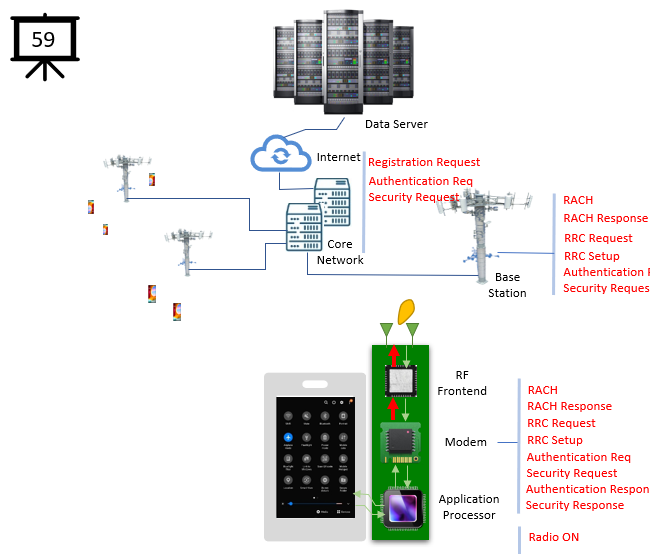
[8] The RACH trigger is conveyed to RF Front End Module (FEM)
NOTE : If you want to know further about RF Front End, check this out.
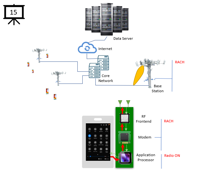
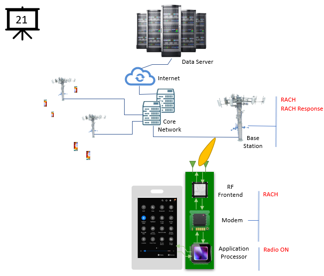
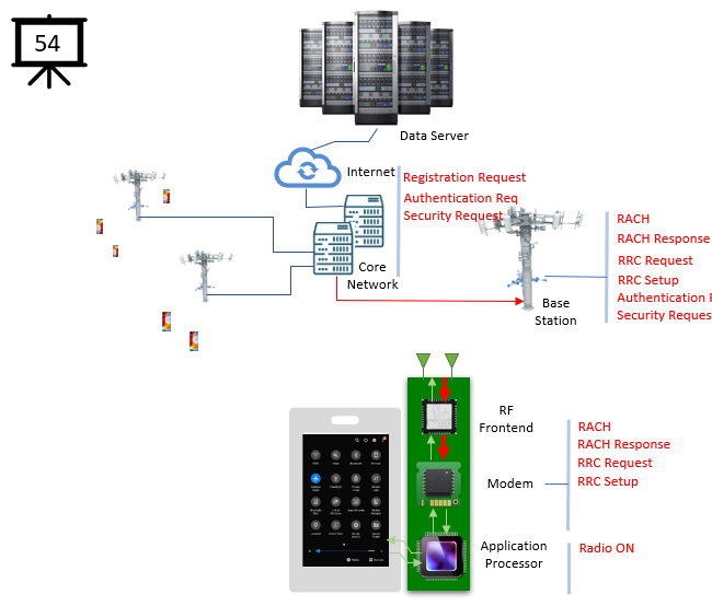
[9] A command from FEM goes to RF hardware (e.g, Antenna)
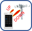
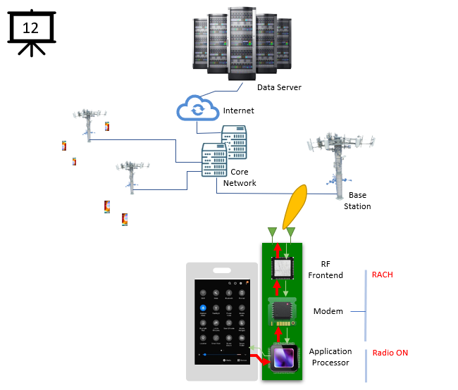
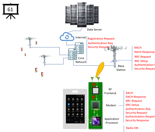
[10]-[14] The RF hadware transmit the signal through the air (channel) and reaches to the RF hardware(antenna) of Base station.
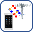
NOTE : While the signal is being transferred, it undergoes a various modification called fading.
NOTE : In case of 5G, a sophisticated process of BeamForming and Beam Management occurs to maintain the stable connection over the air
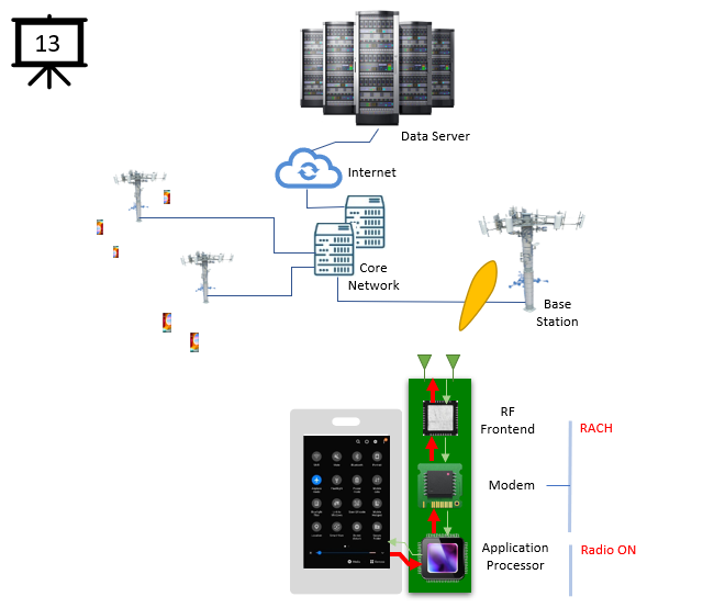
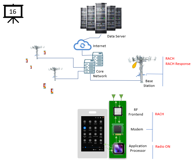
[15] The RF signal is detected and processed in the base station.
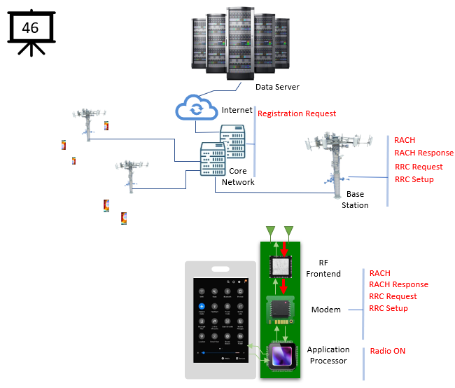
[16]-[21] The response signal is transmitted from Base Station antenna and conveyed to UE Antenna.
NOTE : While the signal is being transferred, it undergoes a various modification called fading.
NOTE : In case of 5G, a sophisticated process of BeamForming and Beam Management occurs to maintain the stable connection over the air
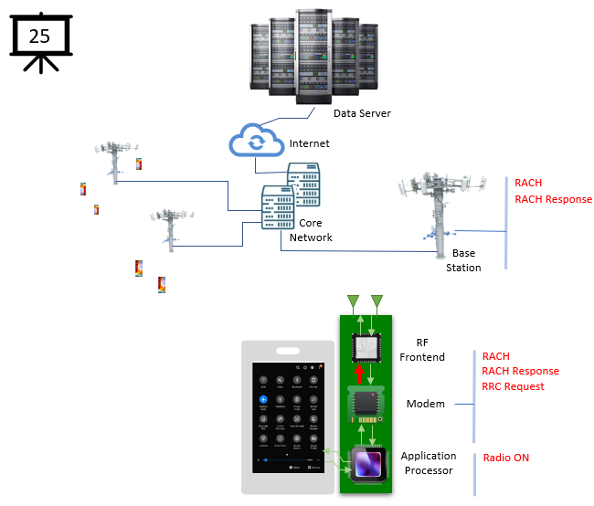
[22] The received signal reaches RF front end chip.
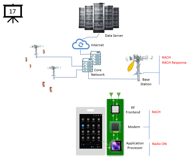
[23] The signal is conveyed to Modem, processed there and recognized as 'RACH Response' signal.
[24] Now the modem chip generated RRC Request message.
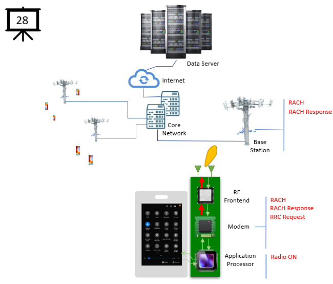
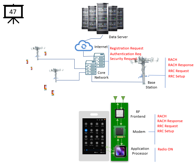
[25] The generated message is transferred to RF Front End
[26] The message goes through RF Front End and relayed to RF hardware (e.g, Antenna)
[27]-[31] The RF hadware transmit the signal through the air (channel) and reaches to the RF hardware(antenna) of Base station.
NOTE : While the signal is being transferred, it undergoes a various modification called fading.
NOTE : In case of 5G, a sophisticated process of BeamForming and Beam Management occurs to maintain the stable connection over the air
[32] The RF signal is detected and processed in the base station.
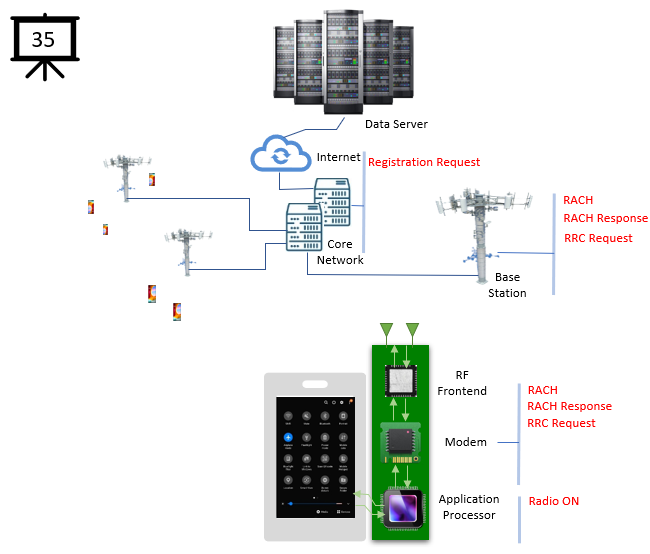
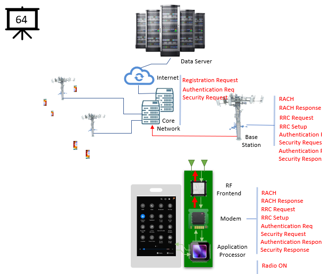
[33] Usually during the RRC Request/Setup process, some messages(Registration Request in case of 5G) destined to Core Network is embedded into the RRC Message and that message is relayed to Core Network.
NOTE : In case of 5G, the message to core network at this step is like this.
[34]-[35] The message is processed within the Core Network.
NOTE : Now it is good time to review overall structure of core network and see how they are connected to each other. Check this out just for big picture.
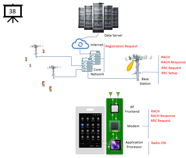
[36] The response signal is generated by Base State and transmitted into air.
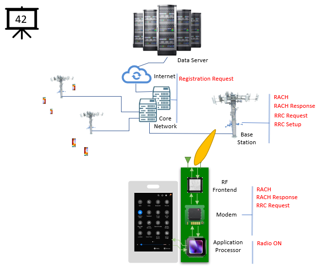
[37]-[43] The response signal from Base Station antenna is propogated to UE Antenna.
NOTE : While the signal is being transferred, it undergoes a various modification called fading.
NOTE : In case of 5G, a sophisticated process of BeamForming and Beam Management occurs to maintain the stable connection over the air
[44] The received signal reaches RF front end chip.
[45]-[46] The signal is conveyed to Modem, processed there and recognized as 'Response' signal(message).
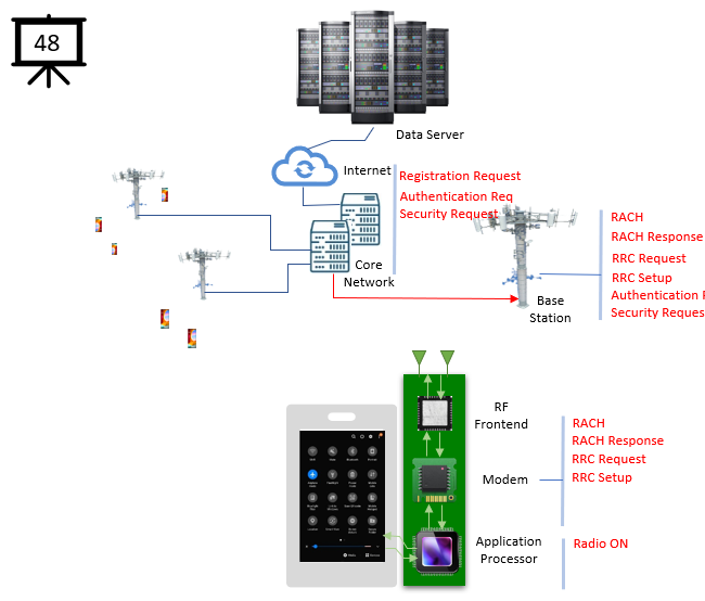
[47] Core Network initiates and generate a sequence of message for Authentication and Security check.
NOTE : In case of 5G, the message and process to core network at this step is like this.
[48] The message is conveyed to Base Station
[49]-[52] The base station transmit the message into the air and it reaches to UE antenna.
NOTE : While the signal is being transferred, it undergoes a various modification called fading.
NOTE : In case of 5G, a sophisticated process of BeamForming and Beam Management occurs to maintain the stable connection over the air
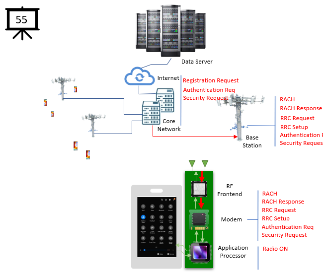
[53] The message is transferred to RF Front End Chip.
[54] The message is transferred to Modem Chip
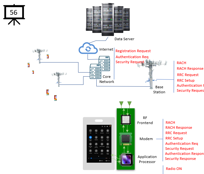
[55] The Modem chip process the received message and recognize/decode Authentication and Security check.
[56] If Moem chip generate the response message for the received message.
[57] The message/signal is traferred to RF Front End Chio
[58] The signal is transferred to RF hardware (antenna)
[59]-[63] The signal is tranmitted into air and reaches Base Station
NOTE : While the signal is being transferred, it undergoes a various modification called fading.
NOTE : In case of 5G, a sophisticated process of BeamForming and Beam Management occurs to maintain the stable connection over the air
[64] The message is received by Base Statio and transmitted to Core Network
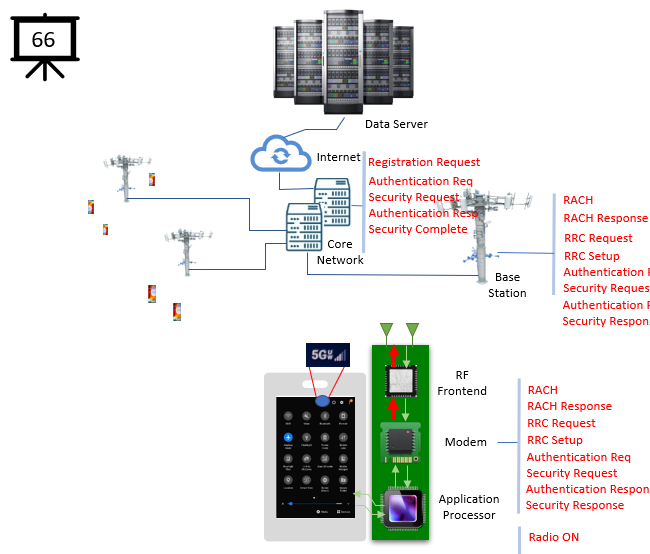
[65] The core network process the received message and this completes the initial registration
NOTE : There may be a few more steps before the completion of the registration (e.g, registration accept etc), but I would stop here and assume the remaining step is properly completed.
[66] Now you get the 5G icon with antenna bars on the UE's display.