The 5G core network architecture is based on a service-based model, utilizing cloud-native and virtualized network functions. The purpose of this note is to share you with overview of 5G corenetwork. The defails of specific components and functionalities will be described in separate notes.
- Overall Architecture
- How to read that diagram
- Reference points and service-based interfaces
- Components of the Network
- Interfaces between Components
- Design Philosophy of 5G Core network
Overall Architecture
What follows is a map of the 5G core, and the first thing to say about it is what it is
The reason there are so many boxes is that 5G took the handful of large nodes that made up the 4G core and broke them into much smaller pieces, each responsible for one question. One function knows where a UE currently is. Another knows what sessions it has open. Another holds the subscription data, another decides what policy applies, another does nothing but forward packets. In 4G several of those jobs lived inside a single node ; in 5G they are separate, and the diagram is busy precisely because that separation is drawn out in full. The useful skill when reading it is not memorising the picture but knowing which box owns which question - and once you know that, finding the right reference point between any two of them is straightforward.
It is also worth remembering that this is a
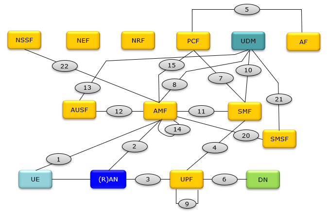
Following is the overal NR Network illustrated based on 23.501. The diagram is based mainly on Figure 4.2.3-1 and Figure 4.2.3-2 of 23.501.
The numbers in the oval shape indicates the reference point between components. This shows NR network only in non-roaming condition. In the condition of roaming with other NR network or Legacy network, some additional function block and interface(reference point) is required.
How to read that diagram
There is a lot in it, so it helps to know what to look at first.
Reference points and service-based interfaces
Your opening paragraph describes 5G core as service-based, and then the diagram and the whole interface list below are reference points with N numbers. Both are correct, and 23.501 genuinely contains both - which is why you noted the diagram is drawn from Figure 4.2.3-1
| Reference point representation | Service based representation | |
|---|---|---|
How it is drawn |
Point to point lines, numbered N |
Every NF hanging off a common bus |
Names things after |
The |
The |
Underneath it is |
A specific protocol for that pair |
HTTP/2 REST, the same for everybody |
Good for |
Seeing the topology, which is why the diagram uses it |
Seeing that any NF can call any other without a new interface being defined |
The important consequence is that
| Reference point | Between | Why it stays point to point |
|---|---|---|
UE and AMF |
The UE is not a network function and has no place on the service bus. NAS is its own protocol |
|
(R)AN and AMF |
The RAN is not part of the core. NGAP over SCTP, much as S1AP was in 4G |
|
the user plane path |
||
SMF and UPF |
Control of the forwarding plane, using PFCP. It is a specialised job with a specialised protocol |
|
MME and AMF |
The far end is a 4G node that has never heard of the service bus |
Everything else in the list - N7, N8, N10, N11, N12, N13, N15, N20, N21, N22 and the rest - describes signalling between two core network functions, and in the service based representation those all become
Components of the Network
There are so many components and functionality. Some of Key components include the Access and Mobility Management Function (AMF), Session Management Function (SMF), User Plane Function (UPF), and Network Repository Function (NRF). The architecture enables network slicing, end-to-end QoS, and efficient resource management.
Followings are the name of each network component. This is the list of the component that are likely to be commonly used in most of the networks, but depending on real deployment you may see more components or in some cases (like small scale private network) you may see much less components where multiple functionalities are aggregated into one component)
AMF Access and Mobility Management Function ==> Equivalent to MME in 4G
AUSF Authentication Server Function
DN Data Network
NEF Network Exposure Function
NRF Network Repository Function
NSSF Network Slice Selection Function
PCF Policy Control Function ==> Equivalent to PCRF in 4G
(R)AN (Radio) Access Network
SMF Session Management Function
UDM Unified Data Management ==> Equivalent to HSS in 4G
UPF User Plane Function ==> Equivalent to PGW in 4G
SMSF SMS Function
The "equivalent to X in 4G" notes above are the fastest way in if you know EPC, but the mapping is not one to one in either direction - and the places where it is
| 4G / EPC | 5G / 5GC | What actually happened |
|---|---|---|
One node became two. The MME handled both mobility and sessions ; 5G splits them, so |
||
Split horizontally rather than vertically. The forwarding half became the UPF and the deciding half went into the SMF - this is CUPS, and it is what lets a UPF sit at the network edge on its own |
||
|
Split three ways : UDM for subscriber logic, UDR for the data itself, AUSF for authentication. Separating the logic from the storage is what makes the data reusable by other functions |
|
The closest thing to a straight rename, though the PCF reaches considerably further |
||
- |
|
No 4G ancestor at all. Service discovery, network slicing, capability exposure and analytics are new jobs that only exist because the architecture became service based and sliceable |
Reading that table downwards, the pattern is that almost nothing was simply renamed. Functions were
Interfaces between Components
The word to pay attention to in that definition is
The list below is long, and the natural reaction is to assume it must be learnt. It does not need to be. The numbering is roughly historical rather than logical - the low numbers are the original Release 15 core, the connections without which a network cannot function at all, and the higher ones were added over time as features arrived. That is why N1 to N15 or so describe registration, sessions and the user plane, while further down you find reference points that exist only because someone later added charging, analytics, public warning, roaming security or slice-specific authentication. A high number generally means a later or optional feature, not a more important one.
In practice nobody reads a list like this from top to bottom. You meet an N number somewhere - in a specification, a log, a vendor diagram - and come to a page like this one to find out which two functions it joins. That is worth knowing because it tells you what the list is really for : it is an index from a name to a pair of endpoints. And it works in both directions, so if you know that the SMF needs to fetch a subscriber's session data from the UDM, you can reasonably expect a reference point to exist for it, and go looking for its number.
One caveat is worth carrying into the list, and it follows from the service-based discussion further up this page. Only a handful of these are protocols you could actually capture on a wire -
Followings are the reference point definition specified in 23.501 - 4.2.7. A reference point is a conceptual point of interaction between two network functions or components.
N1: Reference point between the UE and the AMF.
N2: Reference point between the (R)AN and the AMF.
N3: Reference point between the (R)AN and the UPF.
N4: Reference point between the SMF and the UPF.
N6: Reference point between the UPF and a Data Network.
N9: Reference point between two UPFs.
N5: Reference point between the PCF and an AF.
N7: Reference point between the SMF and the PCF.
N8: Reference point between the UDM and the AMF.
N10: Reference point between the UDM and the SMF.
N11: Reference point between the AMF and the SMF.
N12: Reference point between AMF and AUSF.
N13: Reference point between the UDM and Authentication Server function the AUSF.
N14: Reference point between two AMFs.
N15: Reference point between the PCF and the AMF in the case of non-roaming scenario, PCF in the visited network and AMF in the case of roaming scenario.
N16: Reference point between two SMFs, (in roaming case between SMF in the visited network and the SMF in the home network).
N16a: Reference point between SMF and I-SMF.
N17: Reference point between AMF and 5G-EIR.
N18: Reference point between any NF and UDSF.
N19: Reference point between two PSA UPFs for 5G LAN-type service.
N22: Reference point between AMF and NSSF.
N23: Reference point between PCF and NWDAF.
N24: Reference point between the PCF in the visited network and the PCF in the home network.
N26: Reference point between MME (4G) and AMF
N27: Reference point between NRF in the visited network and the NRF in the home network.
N28: Reference point between PCF and CHF.
N29: Reference point between NEF and SMF.
N30: Reference point between PCF and NEF.
N31: Reference point between the NSSF in the visited network and the NSSF in the home network.
N32: Reference point between SEPP in the visited network and the SEPP in the home network.
N33: Reference point between NEF and AF.
N34: Reference point between NSSF and NWDAF.
N35: Reference point between UDM and UDR.
N36: Reference point between PCF and UDR.
N37: Reference point between NEF and UDR.
N38: Reference point between I-SMFs.
N40: Reference point between SMF and the CHF.
N50: Reference point between AMF and the CBCF.
N51: Reference point between AMF and NEF.
N52: Reference point between NEF and UDM.
N55: Reference point between AMF and the UCMF.
N56: Reference point between NEF and the UCMF.
N57: Reference point between AF and the UCMF.
N41: Reference point between AMF and the CHF in HPLMN.
N42: Reference
N58: Reference point between AMF and the NSSAAF.
N59: Reference point between UDM and the NSSAAF.
| Entry | Should read | Where it shows up |
|---|---|---|
Reference point between AMF and SMSF |
Drawn in the diagram between AMF and SMSF. The list jumps straight from N19 to N22 |
|
Reference point between SMSF and UDM |
Also drawn - it is the line from SMSF up to UDM |
|
- |
The entry currently reads only "N42: Reference", with the definition missing |
The N20 and N21 pair is a small but complete illustration of how a feature is bolted onto this architecture. SMS over NAS needs somewhere to live, so a function is added - the
Design Philosophy of 5G Core network
That reaction is a fair one, and it is worth taking seriously rather than waving away, because the comparison most people are making when they have it is not quite a fair comparison. Set this diagram beside a 4G core and 5G looks like several times the machinery for the same job. But it is not the same job. The 4G core was designed to do one thing well - deliver mobile broadband to handsets - and it was shaped accordingly. The 5G core has to serve a handset streaming video, a factory robot that cannot tolerate a ten millisecond delay, a water meter that wakes up once a day and must run for ten years on one battery, and a car moving at motorway speed, all at the same time and all on the same infrastructure. A single design tuned for any one of those is the wrong design for the other three.
Once you see it that way, the second thing worth noticing is that the complexity did not really increase - it
The reason that trade is worth making is that it lets a network be assembled from only the parts it actually needs. If an operator has no interest in network analytics, the NWDAF is simply never deployed and nothing else has to change. If one slice serves metering devices that never make a voice call, it does not have to carry the machinery that voice would require. And when one function becomes a bottleneck it can be scaled on its own, rather than forcing an upgrade of a large node that happened to contain it. None of that is possible when the functions are welded together, which is the real reason the 4G core could not simply be extended.
It would be dishonest to present this as free. More moving parts means more things to configure, more interfaces to get wrong, and a system that is genuinely harder to troubleshoot - when a call fails you now have several functions to eliminate rather than one or two. Automation and orchestration stop being conveniences and become necessities, because no one is going to configure this by hand. That cost is real, and it is the price paid for the flexibility described below.
At first glance, you may think 5G core is too complicated and look over-designed. There is some design philosophy behind the architecture.
Flexibility : The 5G core network was designed with flexibility in mind, allowing network operators to deploy new services and features quickly and efficiently. This is achieved through the use of network slicing, which enables the creation of virtual networks that can be tailored to specific applications or user groups, providing customized service levels and performance guarantees.Scalability : The 5G core network is designed to be highly scalable, allowing network operators to easily add new users, devices, and services to the network. This is achieved through the use of virtualization, which enables network functions to be separated from the underlying hardware and deployed as software instances. This allows network operators to scale their networks more easily and reduce costs.Virtualization : The 5G core network is designed with virtualization in mind, which allows network functions to be separated from the underlying hardware and deployed as software instances. This enables network operators to deploy and manage network services more efficiently, reduce costs, and scale their networks more easily.Automation : The 5G core network architecture is highly automated, with many of the network functions being automated and managed through software. This automation allows network operators to provision, configure, and manage their networks more efficiently, reducing operational costs and improving network performance.Security : Security is a fundamental design philosophy of the 5G core network architecture. The network is designed with built-in security features such as mutual authentication, encryption, and secure transport protocols to protect against cyber attacks and ensure the privacy and integrity of user data.Cloud-native : The 5G core network architecture is designed to be cloud-native, with network functions deployed as software containers that can run on public, private, or hybrid cloud environments. This allows network operators to take advantage of the scalability and cost-efficiency of cloud computing while maintaining control over their networks.
Reference
- 5G Network Overview (Core) (Sep 2018)
- Service Based Architecture in 5G | Webinar (Jun 2020)
- Open Session -5G Core Protocol and Procedures |5G Call Flow |5G Network |5G Core | SBA| Cloud Native (JUl 2021)
YouTube
- 5G Core Architecture Part 1 Live Session 1st Feb 2022 - 5G Mobile Communications (2022)
- 5G Core Architecture Part 2/3 Live Session 7th April 2021 - 5G Mobile Communications (2021)
- 5G Core Architecture part 3/3 Live Session on 8th April 2021 - 5G Mobile Communications (2021)
- 5G Core Overview | 5G packet Core | Devopedia | - Devopedia (2021)
- 5G CUPS & PFCP - Devopedia (2023)