If you take one idea from this page, make it this one :
That split is the single biggest structural change from 4G, where the SGW and PGW each did both jobs at once - deciding and forwarding, in the same box. Separating them means the part that forwards packets can be small, fast and placed wherever the traffic needs it, close to a factory or a stadium, while the part that makes decisions stays centralised where the policy and subscription data live. It is what makes edge deployment possible at all, and it is the reason the SMF and UPF appear as two boxes in every diagram on this page.
SMF stands for Session Management Function. Simply put, it collects all the informations related to PDU session management from various network components (e.g, UPF, PCF, UDM) and controls / orchastrates those network components based on request from AMF.
- Overall Architecture
- SMF Functionality
- SMF and interaction with other components
- UE-Initiated PDU Sesstion Establishment Process
Overall Architecture
The diagram below is the full core architecture with the SMF's own reference points picked out in blue, and it is worth counting them before reading on. There are
Four is also a telling number in itself. Compare it with the NSSF, which has one, or the AMF, which has nine. The SMF sits in the middle of the range because it needs three different kinds of input before it can do anything - who the subscriber is, what policy applies, and where to send the traffic - and then one channel back to report the result.
The SMF and interactions with other network components within 5G Core network is illustrated below.
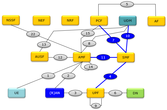
Followings are the name of each network component.
AMF     Access and Mobility Management Function ==> Equivalent to MME in 4G
<hl1>AUSF</hl1>    Authentication Server Function
DN       Data Network
NEF      Network Exposure Function
NRF      Network Repository Function
NSSF    Network Slice Selection Function
PCF      Policy Control Function ==> Equivalent to PCRF in 5G
(R)AN   (Radio) Access Network
SMF     Session Management Function
<hl1>UDM</hl1>     Unified Data Management ==> Equivalent to HSS in 4G
UPF      User Plane Function ==> Equivalent to PGW in 4G
SMSF   SMS Function
<hl1>SEAF</hl1>    SEcurity Anchor Function ==> part of AMF function
<hl1>ARPF</hl1>    Authentication credential Repository and Processing Function</hl1>
<hl1>SIDF</hl1>    Subscription Identifier De-concealing Function
SMF Functionality
The list below is long, but it collapses into three groups once you notice what each item is really about. Some are about
Reading them in those three groups is more useful than reading them in order, because it shows the same pattern repeating : in every case the SMF gathers information from somewhere, converts it into rules, and installs those rules in the UPF. Even charging works this way - the SMF does not count bytes, it tells the UPF which counters to keep and then collects the answers.
Based on 23.501-6.2.2, the functionality of AMF is descrbed as follows. The most fundamental function of SMF is PDU session management and you can take all other functions as subsidiary functions to better manage PDU session.
PDU Session Establishement (23.502-4.3.2) : The SMF is responsible for establishing, modifying, and releasing PDU sessions. These sessions are logical connections between the UE and the Data Network (DN).- a UE initiated PDU Session Establishment procedure.
- a UE initiated PDU Session handover between 3GPP and non-3GPP.
- a UE initiated PDU Session handover from EPS to 5GS.
- a Network triggered PDU Session Establishment procedure.
IP Address Management : It allocates and manages IP addresses for UEs, handling both IPv4 and IPv6 address types. It performs the role of a DHCP server for IP address allocationQoS Management : It configures traffic steering parameters and ensures appropriate routing of packets in the UPFPolicy Control : The SMF interacts with the Policy Control Function (PCF) to receive and implement policy and charging rulesCharging : The SMF handles connectivity charging through interaction with the Charging Function (CHF)Downlink Data Notification : The SMF manages the process of notifying the network when downlink data arrives for an idle UE, initiating paging proceduresSubscription Verification : It checks UE requests against user subscriptions to ensure complianceTraffic usage reporting : The SMF interacts with the User Plane Function (UPF) to collect usage data for each PDU session.Packet routing and forwarding : SMF configures the UPF with the necessary routing and forwarding rules for each PDU session. It instructs the UPF on how to handle incoming and outgoing packets for specific sessions.Traffic steering : The SMF receives policy rules from the PCF that may include traffic steering instructions. Based on these rules, the SMF configures the UPF to apply appropriate traffic steering policies. It can instruct the UPF to route traffic through specific network slices or to particular data networks based on service requirements.
SMF and interaction with other components
The four interfaces described here are not four versions of the same conversation. Each answers a different question, and it is worth having them in mind in the order the SMF actually needs them :
N11 from theAMF "do something" the request that starts everythingN10 from theUDM "who is this?" what the subscription permitsN7 from thePCF "what rules?" the policy to apply to this sessionN4 to theUPF "do this" the only one where the SMF gives orders
Notice the direction of the last one. On three of these interfaces the SMF is asking or being asked ; on N4 it is instructing. That asymmetry is the controller relationship from the top of this page made concrete - and N4 is also the only one of the four that is not a service based interface, because PFCP is a specialised protocol for programming a forwarding plane rather than a general purpose API.
At its core, the SMF is the orchestrator of user sessions. Think of it as the "brain" behind each user's connection to the 5G network. It doesn't just establish and terminate sessions; it dynamically manages them throughout their lifecycle. This includes handling mobility, Quality of Service (QoS) changes, and even applying policy updates in real-time.
SMF interacts with various other components as follows.
- Create a new PDU session: The AMF provides the SMF with information about the user and the requested services, allowing the SMF to establish a dedicated PDU session for the user's data traffic.
- Modify an existing session: If the user's QoS requirements or network conditions change, the AMF can request the SMF to modify the existing session parameters, ensuring optimal performance.
- Terminate a session: When the user disconnects or their session expires, the AMF informs the SMF to release the allocated resources and terminate the PDU session.
- This dynamic interaction between the AMF and SMF ensures that user sessions are efficiently managed throughout their lifecycle, from initial attachment to final detachment.
- Is this user authorized? (Authentication credentials from UDM)
- What services are they subscribed to? (Subscription data from UDM)
- What are their specific data plan limitations? (Data volume, speed caps from UDM)
- Are there any roaming agreements in place? (Roaming information from UDM)
- This information allows the SMF to create a tailored session for the user, ensuring they get the service they expect.
- Route this user's traffic through a specific path. (e.g., for optimized gaming performance)
- Apply this QoS policy to prioritize their video streaming. (e.g., ensuring smooth video calls)
- Enforce data usage limits according to their plan.
- Filter certain types of traffic. (e.g., for parental controls)
- The SMF dynamically adjusts these instructions as needed, based on changing network conditions, user mobility, or policy updates.
- Dynamic QoS adjustments: Imagine a user moving from a Wi-Fi network to a congested 5G cell. The PCF can detect this and instruct the SMF to adjust the QoS parameters, ensuring a seamless experience.
- Charging and billing: The PCF can track data usage and apply the appropriate charging rules based on the user's plan.
- Network slicing: The PCF can assign users to specific network slices with tailored performance characteristics (e.g., low latency for critical IoT devices).
- Security policy enforcement: The PCF can define security policies, and the SMF ensures they are applied to the user's session.
UE-Initiated PDU Sesstion Establishment Process
This is the procedure that turns a registered UE into a UE that can actually send data. Registration got the device known to the network and gave it an identity ; it did not give it a path to the internet. That is what a PDU session is, and establishing one is where most of the SMF's work happens.
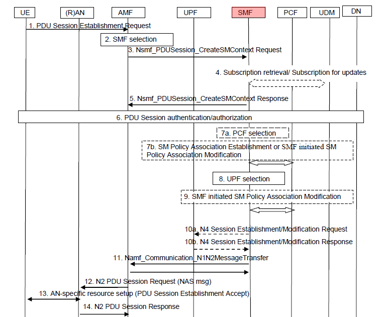
Before reading the fourteen steps, it is worth knowing the shape of the call flow you will see in the figure. The SMF is
The UE-Initiated PDU Session Establishment process in the 5G Core (5GC) network is a fundamental procedure that allows a User Equipment (UE) to establish a Packet Data Unit (PDU) session with the network. This process is essential for the UE to gain access to data services in the 5G network.
The UE-Initiated PDU Session Establishment process in the 5G Core network is a multi-step procedure that involves several network functions working in tandem to set up a data session for the UE. This process ensures that the UE gets the necessary resources and policy treatment for its data traffic.
The high level description on the interaction between SMF and other network components for the PDU session establishment can be described as follows :
PDU Session Establishment Request : The process begins when the UE sends a PDU Session Establishment Request to the Access and Mobility Management Function (AMF). This request contains necessary information such as the desired Slice/Service Type (SST), Session and Service Continuity (SSC) mode, and other relevant parameters.AMF to SMF Request : The AMF forwards the request to the Session Management Function (SMF). The AMF selects an SMF based on the information provided by the UE and other network policies.SMF Interaction with UPF : The SMF interacts with the User Plane Function (UPF) to set up the necessary user plane resources. The UPF is responsible for handling user data traffic and routing it appropriately.Policy Control : The SMF may also interact with the Policy Control Function (PCF) to obtain policy rules for the new PDU session. These rules dictate how the user's data should be treated (e.g., Quality of Service, charging, etc.).PDU Session Establishment Accept : Once the necessary resources are allocated and policy rules are set, the SMF informs the AMF, which in turn sends a PDU Session Establishment Accept message to the UE.Data Transfer : With the PDU session established, the UE can now transfer data with the 5G network. The UPF handles the routing of this data to the appropriate destination, be it the internet, another UE, or a service within the 5G network.Session Context : Throughout the session, the SMF maintains the session context, which contains all the necessary information about the PDU session, such as the allocated resources, policy rules, and other session parameters.
The detailed signaling procedure for PDU session Establishement is depicted in 3GPP as follows :
< 23.502 - Figure 4.3.2.2.1-1: UE-requested PDU Session Establishment for non-roaming and roaming with local breakout >
What happens after step 14
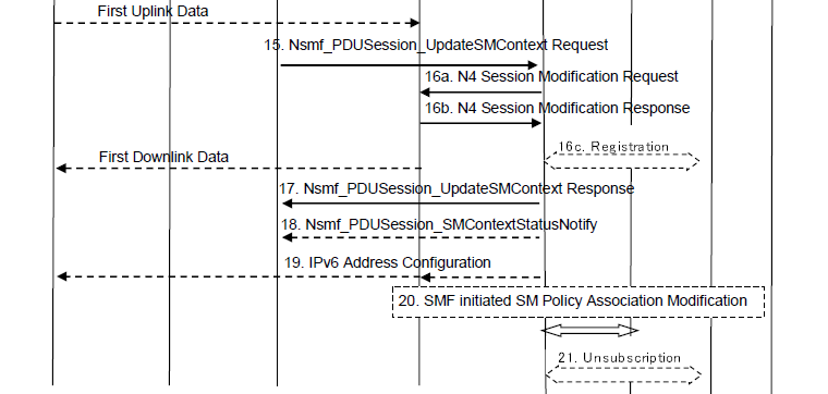
The list above stops at step 14, but the second half of the figure carries on to step 21, and the part it covers is where the session actually starts carrying traffic. It is worth walking because it contains one detail that surprises most people the first time they see it.
At step 14 the radio network has told the AMF that its resources are ready. What it has
15 Nsmf_PDUSession_UpdateSMContext Request AMF -> SMF the AMF passes on what the RAN reported, including the tunnel endpoint the RAN will listen on for downlink traffic16a N4 Session Modification Request SMF -> UPF16b N4 Session Modification Response UPF -> SMF the SMF installs that endpoint in the UPF, so the UPF finally knows where to send downlink packets17 Nsmf_PDUSession_UpdateSMContext Response SMF -> AMF18 Nsmf_PDUSession_SMContextStatusNotify SMF -> AMF19 IPv6 Address Configuration to the UE, if IPv6 is used20 SMF initiated SM Policy Association Modification optional, back to the PCF21 Unsubscription optional, tidy-up with the UDM
Uplink works as soon as the radio bearer exists, because the RAN was told where the UPF is when the session was set up - it can start forwarding the moment the UE has something to send. Downlink cannot, because until step 16 the UPF has no idea which RAN node to send to or over which tunnel. The information travels UE side first and only reaches the UPF once the AMF has relayed it to the SMF and the SMF has programmed it in.
So for a brief window a PDU session is genuinely half open - the UE can talk but cannot be answered. It is short enough that nothing notices, but it explains something that otherwise looks odd in a trace : the first uplink packet of a session can appear before the procedure that establishes it has finished.
Reference :
- What is the 5G Session Management Function (SMF)? - Microsoft
- 5G System Overview - 3GPP
- Network Function | Session Management Function (SMF) in 5G Core Network | 5G System (5GS) - TECHTRAINED
YouTube
- 5G Session Management Signalling Analysis - Taha Sajid - (2021)
- 5G Core - Session Management Function (SMF) -Raghvendra Agarwal (2022)