In LTE, I haven't seen much case of UL MIMO being really used even though it is defined in 3GPP specification. In NR, as of now (Apr 2022), I still don't see UL MIMO being used in wide scale but I am expecting it to be used more (at least more than LTE MIMO).
- How UL MIMO is configured ?
- MIMO Configuration Table : Precoding Information and Number of Layers
- MIMO Configuration Table : Antenna Port Configuration
- MIMO Configuration Table : Precoding Matrix
- Examples
- Get the Test Procedure and Log / Amarisoft TechAcademy
How UL MIMO is configured ?
In NR, Downlink MIMO is configured by relatively straight forward manner (i.e, only by Antenna Port in DCI) as described in this page. But UL MIMO configuration is more complicated and multiple types of tables and multiple fields in DCI are working together to configure UL MIMO. Followings are the summary of those tables related to configuring UL MIMO.
< Precoding information and number of layers >
|
txConfig(UL) |
Antenna |
PUSCH-tp |
maxRank |
Codebook Subset |
ul- FullPowerTransmission |
Bit Length |
Table in 38.212 |
|
NonCodeBook |
|
|
|
|
|
0 |
|
|
CodeBook |
4 ports |
Disabled |
2 or 3 or 4 |
(1), (2) ,(3) |
N/A or fullpowerMode2 or fullpower |
4 or 5 or 6 |
|
|
CodeBook |
4 ports |
Disabled |
2 |
(2) ,(3) |
fullpowerMode1 |
4 or 5 |
|
|
CodeBook |
4 ports |
Disabled |
3 or 4 |
(2) ,(3) |
fullpowerMode1 |
4 or 6 |
|
|
CodeBook |
4 ports |
Disabled |
|
(1), (2) ,(3) |
N/A or fullpowerMode2 or fullpower |
2 or 4 or 5 |
|
|
Enabled |
1 |
||||||
|
CodeBook |
4 ports |
Disabled |
|
(2),(3) |
fullpowerMode1 |
3 or 4 |
|
|
Enabled |
1 |
||||||
|
CodeBook |
2 ports |
disabled |
2 |
(1) , (3) |
N/A or fullpowerMode2 or fullpower |
3 or 4 |
|
|
CodeBook |
2 ports |
disabled |
2 |
(3) |
fullpowerMode1 |
2 or 4 |
|
|
CodeBook |
2 ports |
Disabled |
1 |
(1) ,(3) |
N/A or fullpowerMode2 or fullpower |
2 or 3 |
|
|
Enabled |
2 |
||||||
|
CodeBook |
2 ports |
Disabled |
1 |
(3) |
fullpowerMode1 |
2 |
|
|
Enabled |
(3) |
fullpowerMode1 |
Precoding Matrix Selection
The table shown below works as a bridge between the uplink logical transmission and the actual antenna ports used by the UE in 5G NR. It tells you which table in 3GPP TS 38.211 should be used to find the real precoding matrix. That matrix is the actual complex-number weight applied to each layer before transmission.
The first point of this table is the relationship between the number of layers and the number of antenna ports. The number of layers means how many independent data streams the UE is transmitting. The number of antenna ports means how many transmission paths are available at the PHY level. In general, the number of layers cannot exceed the number of antenna ports. This is the basic constraint for uplink MIMO transmission.
The second point is the dependency on transform precoding. This is an important distinction in NR uplink. If transform precoding is enabled, the UE uses DFT-s-OFDM. This waveform is chosen mainly for lower PAPR, so it helps power efficiency and uplink coverage. In this case, the UE should use the precoding matrices defined in the corresponding 38.211 table for transform-precoded transmission. If transform precoding is disabled, the UE uses CP-OFDM. This is more suitable for higher throughput and more flexible transmission. In that case, the UE should use a different 38.211 table defined for non-transform-precoded uplink.
|
# of Layers |
# of Antenna Ports |
Transform Precoding |
Precoding Matrix (38.211) |
|
1 |
2 |
|
|
|
4 |
enabled |
||
|
disabled |
|||
|
2 |
2 |
disabled |
|
|
4 |
disabled |
||
|
3 |
4 |
disabled |
|
|
4 |
4 |
disabled |
It mean that the gNB sends DCI to the UE. In that DCI, there is TPMI. TPMI is not the matrix itself. It is just an indicator. The UE first uses the related table in 38.212 to interpret that TPMI value. Then that result points to the proper table in 38.211. From that table, the UE finally gets the actual precoding matrix.
So this table is not showing the matrix itself. Instead, it tells us where to find the correct matrix depending on the number of layers, the number of antenna ports, and whether transform precoding is enabled or disabled. In other words, this table tells us which 3GPP dictionary to open to get the exact MIMO precoding math used for the uplink physical layer.
Antenna Port Selection
This table shown below explains how the UE interprets the Antenna Ports field in DCI for PUSCH transmission. It tells the UE which DMRS ports are assigned for the uplink transmission. In simple terms, this table acts like an addressing guide for the uplink MIMO layers.
The first thing this table shows is whether transform precoding is enabled or disabled. If PUSCH transform precoding is enabled, the waveform is DFT-s-OFDM. In this case, the Rank column is empty. This is because transform precoding in normal NR operation supports only single-layer transmission. So the UE does not need to consider multiple MIMO layers here. If transform precoding is disabled, the waveform is CP-OFDM. In this case, multi-layer transmission is supported, and the table shows the cases for different ranks.
The next part of the table is determined by the DMRS configuration parameters. These parameters define the structure of the reference signals used for demodulation. One parameter is DMRS-config-type. If it is Type 1, the UE uses the Type 1 DMRS pattern. This supports up to 8 ports and is based on a comb-like frequency-domain structure. If it is Type 2, the UE uses the Type 2 DMRS pattern. This supports up to 12 ports and uses a more detailed grouping structure such as fd-CDM. So this parameter affects how many ports can be supported and how they are arranged.
Another important parameter is DMRS-config-max-len. This tells whether the DMRS occupies one OFDM symbol or two OFDM symbols in time. If the length is 2, more orthogonal DMRS ports can be supported. As a result, the Antenna Ports field in DCI may need more bits. That is why the bit length changes depending on this parameter.
The Bit Length column tells the UE how many bits should be read from the Antenna Ports field in the DCI. This is important because the DCI does not directly list the port numbers. Instead, it carries a bit field. The UE reads that field with the correct bit length, and then uses the referenced table in 38.212 to decode it.
Overall, this table is a guide for decoding the Antenna Ports field in DCI. It says that if the UE has a certain waveform type, DMRS configuration type, and DMRS maximum length, then the Antenna Ports field will have a certain number of bits, and the UE must use a specific 38.212 table to interpret it. This is a good example showing that dynamic control signaling in DCI depends completely on the semi-static configuration delivered by RRC.
|
PUSCH-tp |
DMRS-config-type |
DMRS-config-max-len |
Rank |
Bit Lenth |
Table in 38.212 |
|
Enabled |
1 |
1 |
|
2 |
|
|
1 |
2 |
|
4 |
||
|
Disabled |
1 |
1 |
1 |
3 |
|
|
1 |
1 |
2 |
3 |
||
|
1 |
1 |
3 |
3 |
||
|
1 |
1 |
4 |
3 |
||
|
Disabled |
1 |
2 |
1 |
4 |
|
|
1 |
2 |
2 |
4 |
||
|
1 |
2 |
3 |
4 |
||
|
1 |
2 |
4 |
4 |
||
|
Disabled |
2 |
1 |
1 |
4 |
|
|
2 |
1 |
2 |
4 |
||
|
2 |
1 |
3 |
4 |
||
|
2 |
1 |
4 |
4 |
||
|
Disabled |
2 |
2 |
1 |
5 |
|
|
2 |
2 |
2 |
5 |
||
|
2 |
2 |
3 |
5 |
||
|
2 |
2 |
4 |
5 |
MIMO Configuration Table : Precoding Information and Number of Layers
These tables in 3GPP TS 38.212 act as the instruction guide that tells the UE how to interpret a specific field in the DCI. The DCI does not directly contain detailed transmission parameters. Instead, it carries compact indicators. The UE must interpret those indicators using predefined tables in the specification.
Because 5G NR supports many different hardware configurations and transmission modes, a single universal table would be too large and inefficient. Instead, the system relies on RRC configuration to narrow down which specific table the UE should use. The RRC parameters act as a pre-selection mechanism. Based on these semi-static configurations, the UE determines the correct table and the correct bit length of the related DCI field.
At a high level, the UE works like a conditional decoder. The UE first checks its configuration parameters, such as the number of antenna ports and whether transform precoding is enabled. These parameters determine which group of tables applies. For example, if the UE supports four antenna ports, it selects from the table family designed for four-port operation. If the UE supports only two antenna ports, it selects from a different table family. This step also determines how many bits should be read from the corresponding DCI field.
Another important aspect is Full Power Transmission (FPT). Some tables, such as 7.3.1.1.2-2A or 7.3.1.1.2-2B, are extensions of the baseline tables. These are associated with the fullpowerMode1 feature introduced in Release 16. Normally, when fewer antenna ports are used, the UE may reduce its transmit power per port. Full power transmission allows the UE to use its maximum rated power even if not all ports are active. This helps maintain coverage, especially near the cell edge.
The tables are also separated based on whether transform precoding is enabled or disabled. If transform precoding is disabled, the UE uses CP-OFDM. This mode supports full MIMO operation and multiple transmission layers. If transform precoding is enabled, the UE uses DFT-s-OFDM, which behaves more like a single-carrier waveform. In this case, the transmission is typically limited to Rank 1. The focus is on improving power efficiency and uplink coverage rather than maximizing throughput.
Each entry in these tables provides two important indicators. The first one is TRI (Transmission Rank Indicator). This tells the UE how many layers should be transmitted. The second one is TPMI (Transmitted Precoding Matrix Indicator). TPMI identifies which precoding matrix should be used. The actual matrix values are defined in 3GPP TS 38.211, so the UE uses the TPMI index to retrieve the correct matrix from those tables.
Overall, these tables serve as a structured decoding guide for the UE. They define how the UE translates a compact DCI field into actual transmission parameters. The process starts from the RRC configuration, which determines the applicable table family. The UE then reads the DCI bits, obtains the TRI and TPMI values, and finally retrieves the actual precoding matrix from the physical layer tables in 38.211.
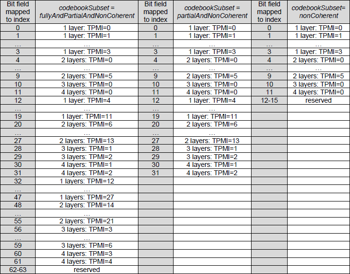
< 38.212 - Table 7.3.1.1.2-2: Precoding information and number of layers, for 4 antenna ports, if transform precoder is disabled, maxRank = 2 or 3 or 4, and ul-FullPowerTransmission is not configured or configured to fullpowerMode2 or configured to fullpower >
This table is the final decoding step for Table 7.3.1.1.2-2 in 3GPP TS 38.212. It converts the raw bit-field value carried in DCI into two actual transmission commands for the UE. One is the transmission rank, meaning how many layers to send. The other is TPMI, meaning which precoding matrix to use.
The table is divided by the codebookSubset setting. This setting is given by RRC and acts as a filter on which precoding choices the UE is allowed to use. If the setting is fullyAndPartialAndNonCoherent, the UE can use the widest set of matrices. So the table is larger and the DCI field needs more bits. If the setting is partialAndNonCoherent, the UE can use a smaller set of matrices. So the table becomes shorter and fewer bits are needed. If the setting is nonCoherent, only the most restricted set of mappings is allowed. In that case, the table is the smallest and the DCI field is the shortest.
An important point is that this table combines rank selection and precoding selection in one place. The gNB does not need one DCI field for rank and another field for TPMI. Instead, one bit-field value directly tells the UE both how many layers to use and which precoding matrix to apply. This makes the control signaling compact and efficient.
The mapping is not just a simple linear list. The entries are grouped by allowed transmission cases. In one range of values, the UE is instructed to use one layer. In another range, it uses two layers. In some entries, it can move to three or four layers. As the codebookSubset becomes more restrictive, more choices disappear. That is why the table gets shorter and why some values are effectively unavailable.
At a high level, this table is the execution stage of uplink codebook control. Earlier tables and RRC parameters define the allowed operating space. This table is where the actual DCI value tells the UE what to do at that moment. Even with the same semi-static configuration, the gNB can quickly change the uplink behavior by changing only the DCI index. For example, it can move the UE from higher-rank transmission to one-layer transmission when radio condition becomes worse.
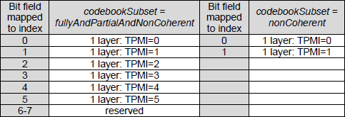
< 38.212 - Table 7.3.1.1.2-2A: Precoding information and number of layers for 4 antenna ports, if transform precoder is disabled, maxRank = 2, and ul-FullPowerTransmission = fullpowerMode1 >
This table, 7.3.1.1.2-2A, is a special version of the uplink precoding decoding table for Full Power Transmission Mode 1. It is used when the UE supports uplink full power operation and the network wants to improve coverage rather than maximize MIMO throughput.
The main purpose of this table is to let the UE use its available transmit power more effectively even when it is transmitting only one or two layers. In normal MIMO operation, a lower-rank transmission may not fully utilize all antenna paths or power amplifiers. This table provides specific TPMI choices that allow the UE to spread the transmission in a way that better uses the available power. As a result, the UE can maintain stronger uplink transmission, which is especially useful at the cell edge or in poor radio conditions.
This table is only relevant when ul-FullPowerTransmission is configured as fullpowerMode1. That means it is not a general-purpose table for all uplink cases. It is a specialized table for a specific operating mode where power efficiency and link budget are more important than high-rank spatial multiplexing.
Compared to the normal codebook table, this one supports a more restricted set of codebook subsets. It does not include the fullyAndPartialAndNonCoherent case. This means the table is intended for more limited or more specialized hardware situations where only partial or non-coherent precoding choices are meaningful.
Another important characteristic is that the table is limited to a maximum rank of 2. Even though the UE may have 4 antenna ports, the network intentionally limits the transmission to one or two layers. This shows that the goal here is not to push the highest number of parallel streams. The goal is to keep good power concentration and reliable uplink coverage.
The TPMI mapping in this table is also different from the normal table. Some higher-index TPMIs appear in places that look unusual compared to the baseline mapping. These TPMIs correspond to full-power-oriented precoding matrices. In other words, they are selected because they help combine antenna resources in a way that supports stronger low-rank transmission.
At a high level, this table is a power-optimized decoder for uplink precoding. It tells the UE that, under Full Power Mode 1, the DCI field should be interpreted using a special mapping that favors stronger and more robust one-layer or two-layer transmission instead of higher-rank MIMO.
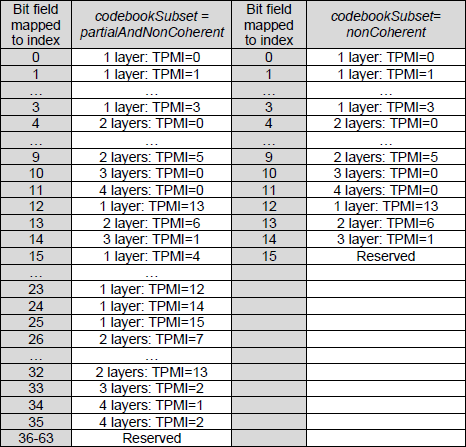
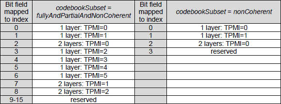
< 38.212 - Table 7.3.1.1.2-2B: Precoding information and number of layers for 4 antenna ports, if transform precoder is disabled, maxRank = 3 or 4, and ul-FullPowerTransmission = fullpowerMode1 >
This table, 7.3.1.1.2-2B, is the extended Full Power Mode 1 decoding table for a 4-port UE. It is used when the network allows not only low-rank transmission but also higher-rank transmission up to Rank 3 or Rank 4. In simple terms, this table supports both strong coverage-oriented transmission and high-capacity spatial multiplexing within the same framework.
The main idea of this table is to give the gNB maximum flexibility. With one DCI field, the gNB can move the UE between single-layer transmission for better coverage and multi-layer transmission for higher throughput. This means the UE can operate in a more coverage-focused mode when radio condition is poor, and then move to a more capacity-focused mode when radio condition becomes better.
Compared to Table 7.3.1.1.2-2A, this table covers a wider range of TPMI entries. This is because Rank 3 and Rank 4 transmission need additional precoding choices. As the number of supported layers increases, the number of valid combinations also increases. That is why this table is larger and why the DCI field needs enough space to represent more indices.
The mapping in this table is grouped in a logical way. The lower part of the index range corresponds to more standard mappings across Rank 1 to Rank 4. Then additional entries are included for Full Power specific operation. In those entries, some special TPMI values appear again for one-layer transmission. These are important because they represent matrices that allow the UE to use its power amplifiers more effectively even when only a single data stream is transmitted.
The effect of codebook subset is still very important here. If the UE supports only nonCoherent operation, the usable part of the table becomes much smaller. This is because many advanced precoding combinations require phase coherence across antenna ports. If the UE cannot support that, many entries become reserved and cannot be used.
At a high level, this table is the most flexible member of the 4-port Full Power Mode 1 family. Table 7.3.1.1.2-2 is the normal table for standard uplink codebook transmission. Table 7.3.1.1.2-2A focuses on Full Power operation for Rank 1 and Rank 2. Table 7.3.1.1.2-2B extends that idea further and supports Full Power operation across Rank 1 to Rank 4. So this table can be viewed as the hybrid mode that combines coverage improvement and throughput expansion in a single decoding structure.
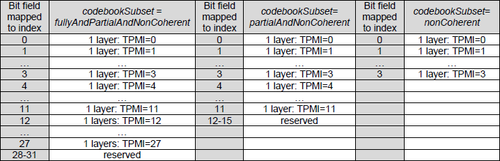
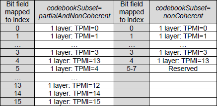
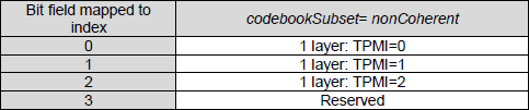
< 38.212 - Table 7.3.1.1.2-3: Precoding information and number of layers for 4 antenna ports, if transform precoder is enabled and ul-FullPowerTransmission is either not configured or configured to fullpowerMode2, or if transform precoder is disabled, maxRank = 1, and ul-FullPowerTransmission is not configured or configured to fullpowerMode2 or configured to fullpower >
This table, 7.3.1.1.2-3, is the single-layer uplink precoding table for a 4-port UE. It is used in cases where the network wants to focus on reliability and coverage rather than maximum throughput. In this table, every entry corresponds to only one layer. That means the UE always sends a single data stream, and the only thing that changes is which precoding direction is selected through TPMI.
This table is closely related to transform precoding. When transform precoding is enabled, the uplink waveform becomes DFT-s-OFDM. In current NR operation, this mode supports only single-layer transmission. That is why this table contains only Rank 1 entries. There is no need to include Rank 2, Rank 3, or Rank 4 choices here.
The codebookSubset still affects how many TPMI choices are available. If the subset is fullyAndPartialAndNonCoherent, the UE can use the largest set of precoding directions, so the table is longer and the DCI field needs more bits. If the subset is partialAndNonCoherent, the number of available choices becomes smaller, so the DCI field becomes shorter. If the subset is nonCoherent, only a very limited set of precoding directions can be used, so the DCI field becomes very small. This makes the control signaling simpler and more robust.
This table is also the baseline case for normal power operation or Full Power Mode 2. In this mode, the UE handles its own power distribution, so the network does not need the special Full Power Mode 1 TPMI mappings that appear in the A and B tables. In other words, this table is simpler because it does not include those special full-power-specific beam choices.
At a high level, this table shows that uplink link adaptation is not only about changing MCS. The gNB can also decide to keep the transmission in single-layer mode and use this table so that all transmission energy is concentrated into one layer. This improves robustness when the radio condition is weak, such as near the cell edge or in other low-SNR situations.
So this table is mainly used when the UE is operating with transform precoding enabled, when the network wants maximum uplink reliability, or when the UE capability itself is limited to Rank 1. In all of these cases, the role of the DCI field is simply to choose the best single-layer precoding matrix from the allowed set.
< 38.212 - Table 7.3.1.1.2-3A: Precoding information and number of layers for 4 antenna ports, if transform precoder is enabled and ul-FullPowerTransmission = fullpowerMode1, or if transform precoder is disabled, maxRank = 1, and ul-FullPowerTransmission = fullpowerMode1 >
This table, 7.3.1.1.2-3A, is the most coverage-focused table for 4-port uplink MIMO. It is used only for Full Power Transmission Mode 1 when the UE is restricted to Rank 1. This can happen because the network intentionally chooses one-layer transmission, or because transform precoding is enabled and only single-layer transmission is allowed.
The purpose of this table is simple. It helps the UE send one very strong uplink stream instead of trying to send multiple layers. This is useful when the UE is near the cell edge or when radio condition is poor. In this situation, the network wants to maximize link budget rather than increase throughput.
This table is the Rank-1 version of the other Full Power Mode 1 tables such as 2A and 2B. Those tables support one or more layers depending on configuration. This table supports only one layer. That means the DCI does not control rank switching here. It only selects which single-layer precoding matrix the UE should use.
One important point in this table is the appearance of TPMI 13, 14, and 15 in an emphasized way. These TPMIs are important because they correspond to special full-power-oriented precoding matrices. They allow the UE to combine power across multiple antenna ports while still sending only one layer. In practice, this gives the UE a stronger and more robust uplink transmission.
Another important aspect is DCI compactness. Since the table supports only restricted codebook subsets and only Rank 1 operation, the DCI field can be shorter than in more general tables. This is helpful because this table is meant for poor signal conditions. A shorter control field is easier to decode correctly, so it improves reliability not only for data transmission but also for the control signaling itself.
This table is also flexible in waveform choice. It can be used with CP-OFDM or with DFT-s-OFDM, as long as Full Power Mode 1 is active and the UE is operating in Rank 1. In many practical cases, it is closely associated with DFT-s-OFDM because both focus on robust uplink transmission and better power efficiency.
At a high level, this table is the final full-power coverage booster in the 4-port family. Table 2A supports Full Power Mode 1 with up to two layers. Table 2B extends that to higher-rank operation. Table 3A is the extreme reliability case. It keeps the UE at one layer and uses special TPMI choices so that as much transmission power as possible is concentrated into a single strong uplink stream.
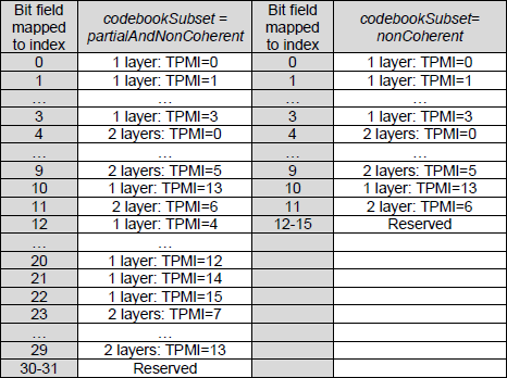
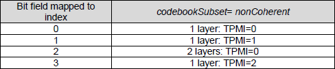
< 38.212 - Table 7.3.1.1.2-4: Precoding information and number of layers, for 2 antenna ports, if transform precoder is disabled, maxRank = 2, and ul-FullPowerTransmission is not configured or configured to fullpowerMode2 or configured to fullpower >
This table, 7.3.1.1.2-4, is the baseline decoding table for 2-port uplink MIMO. It is used when the UE has two antenna ports and transform precoding is disabled, so the uplink waveform is CP-OFDM. Compared to the 4-port case, everything becomes simpler because the UE has fewer antenna ports and therefore fewer possible transmission combinations.
Since there are only two antenna ports, the maximum transmission rank is limited to two layers. For this reason, the table only needs to switch between one-layer transmission and two-layer transmission. In good radio condition, the network can choose two layers for higher throughput. In weaker radio condition, it can move to one layer for better robustness.
The codebook subset structure is also simpler than in the 4-port case. For 2-port operation, the specification reduces the choices to fewer subset types. If the UE is configured with fullyAndPartialAndNonCoherent, it can use the full set of supported 2-port precoding matrices. In this case, the DCI field is a little longer because more TPMI choices are possible. If the UE is configured with nonCoherent, only the most restricted mappings are allowed. Then the DCI field becomes shorter because the number of valid entries is much smaller.
The TPMI values in this table point to a much smaller precoding matrix set in 38.211. For one-layer transmission, the selected matrix is a 2 x 1 vector. For two-layer transmission, the selected matrix is a 2 x 2 matrix. So the overall decoding logic is the same as in the 4-port case, but the number of possible matrices is much smaller.
This table is the standard version for 2-port operation. It does not include the special Full Power Mode 1 mappings. That means it is used for normal uplink codebook transmission or for cases where the UE handles power distribution without needing the special full-power-oriented TPMI patterns.
At a high level, this table shows how NR uplink codebook design scales down for simpler UE hardware. In the 4-port case, the table is larger because more layers and more precoding combinations are possible. In the 2-port case, the table becomes much smaller because the UE capability itself is smaller. This makes the DCI field shorter, the decoding logic simpler, and the whole MIMO control process more compact. It is a good example showing that the NR uplink control design grows or shrinks according to the actual hardware capability of the UE.
< 38.212 - Table 7.3.1.1.2-4A: Precoding information and number of layers, for 2 antenna ports, if transform precoder is disabled, maxRank = 2, and ul-FullPowerTransmission = fullpowerMode1 >
This table, 7.3.1.1.2-4A, is a very compact decoding table for 2-port UEs operating in Full Power Transmission Mode 1. It is designed for a simple but important case where the network wants to improve uplink coverage and power efficiency on a UE with only two antenna ports.
The first thing to notice is that this table is extremely small. It has only four index values, so the DCI field needs only 2 bits. This makes the control signaling very compact. That is important because this table is mainly used in difficult radio conditions where reliable DCI reception is also critical.
Another important point is that this table supports only the nonCoherent codebook subset. This means the UE is restricted to the simplest antenna port relationships. In this mode, the specification removes more complex coherent precoding choices and keeps only the most basic mappings. This reduces implementation complexity and makes the operation more robust.
Even with this strong simplification, the table still gives the network useful control. The gNB can still switch between Rank 1 and Rank 2 depending on the radio condition. If coverage is the main concern, it can keep the UE at one layer. If the condition becomes better, it can move to two layers.
The key benefit of this table comes from the Full Power Mode 1 precoding choice. In particular, the inclusion of TPMI 2 is important. This allows a one-layer transmission to make use of both antenna ports together. As a result, the UE can concentrate more transmit power into a single uplink stream. This helps improve link budget and is especially useful near the cell edge.
At a high level, this table is the simplified full-power version of the normal 2-port codebook table. The standard 2-port table supports more choices and longer DCI signaling. This table removes almost everything except the most essential options. So it is a good example of how 3GPP reduces complexity when the priority shifts from general MIMO flexibility to maximum uplink robustness and coverage.
< 38.212 - Table 7.3.1.1.2-5: Precoding information and number of layers, for 2 antenna ports, if transform precoder is enabled and ul-FullPowerTransmission is not configured or configured to fullpowerMode2 or configured to fullpower, or if transform precoder is disabled, maxRank = 1, and and ul-FullPowerTransmission is not configured or configured to fullpowerMode2 or configured to fullpower >
This table, 7.3.1.1.2-5, is the baseline single-layer decoding table for a 2-port UE. It is used when the network wants maximum uplink reliability rather than higher throughput. In this table, the UE always transmits only one layer, so the DCI field does not switch between Rank 1 and Rank 2. It only tells the UE which single-layer precoding matrix to use.
This table is the 2-port counterpart of Table 7.3.1.1.2-3. The main idea is the same. The network has already decided that one-layer transmission is better for the current situation. This often happens when transform precoding is enabled, so the waveform is DFT-s-OFDM, or when the UE capability is limited to maxRank = 1.
Because the UE has only two antenna ports and only one transmission layer is allowed, the mapping becomes very small. If the codebook subset is fullyAndPartialAndNonCoherent, the UE can choose from a small set of single-layer precoding directions, so the DCI field needs only a few bits. If the codebook subset is nonCoherent, the number of choices becomes even smaller, so the DCI field can be reduced to the minimum size. This makes the control signaling very compact and robust.
This table is used for normal power operation or for Full Power Mode 2. In these cases, the UE manages its own internal power handling, so the table does not need the special Full Power Mode 1 precoding entries. That is why this table is simpler than the full-power-specific versions.
At a high level, this table represents the safe and robust uplink mode for 2-port hardware. When radio condition is not good enough for multi-layer transmission, the network can move the UE from the 2-port multi-layer table to this single-layer table. This allows all transmission energy to be focused into one stream, which improves coverage and link stability.
So this table is mainly used when the uplink should favor stability over speed. It is especially relevant for transform-precoded uplink, low-SNR conditions, and simple 2-port UE implementations where reliable single-layer transmission is the main goal.
< 38.212 - Table 7.3.1.1.2-5A: Precoding information and number of layers, for 2 antenna ports, if transform precoder is enabled and ul-FullPowerTransmission = fullpowerMode1, or if transform precoder is disabled, maxRank = 1, and ul-FullPowerTransmission = fullpowerMode1 >
Table 7.3.1.1.2-5A is the final and most restricted configuration in the 2-port uplink precoding tables. It is used when Full Power Transmission Mode 1 is active and the UE is operating strictly with one transmission layer. This situation occurs either when transform precoding is enabled or when the UE is configured with maxRank equal to one while using Full Power Mode 1.
In this table, the UE always transmits a single layer. The DCI field does not control rank selection because only Rank 1 is allowed. The only purpose of the DCI field is to select which single-layer precoding vector should be used.
The table supports only the nonCoherent codebook subset. This means the UE uses the simplest antenna mapping where strict phase coherence between antenna ports is not required. Because of this restriction, the number of possible TPMI choices becomes very small.
Only three TPMI values are defined. These correspond to three different single-layer precoding vectors for the two antenna ports. The DCI field therefore needs only two bits. One of the possible bit values is reserved, which further simplifies the decoding logic.
The key purpose of this table is to support Full Power Mode 1 operation for a 2-port UE in the most robust configuration possible. Even though only one data stream is transmitted, the UE can still use both antenna ports in a way that allows its power amplifiers to contribute effectively to the transmission. This improves uplink coverage and link reliability, especially when the UE is far from the base station.
At a high level, this table represents the most coverage-focused mode in the entire 2-port uplink codebook family. The UE sends only one layer, uses the simplest precoding options, and relies on a very small DCI field. This combination minimizes control signaling complexity while maximizing the probability that the uplink transmission remains reliable in very weak signal conditions.

MIMO Configuration Table : Antenna Port Configuration
This section of TS 38.212 explains how the Antenna Port field in DCI is interpreted to determine which DMRS ports are used during uplink transmission. These tables do not control the beamforming direction like the precoding matrices. Instead, they define the reference signals that the gNB uses to estimate the channel and decode the received data.
In uplink transmission, the gNB relies on DMRS signals to understand how the radio channel affects the transmitted waveform. The Antenna Port field in DCI tells the UE which DMRS port configuration to use. Each configuration determines how the reference signals are mapped in the resource grid and how they are separated using CDM groups.
One important factor in these tables is the DMRS configuration type. There are two main types. Type 1 is optimized for typical MIMO operation and supports up to eight DMRS ports. It uses a comb-like structure in the frequency domain, which is efficient and commonly used for standard uplink transmissions. Type 2 supports up to twelve ports and uses a more complex resource element pattern. This allows more layers or users to share the same time and frequency resources.
Another parameter that affects the table selection is maxLength. This parameter determines how many OFDM symbols are used for DMRS in the time domain. When maxLength is equal to one, the reference signal occupies only one OFDM symbol. This reduces overhead and improves spectral efficiency. When maxLength is equal to two, an additional symbol is used for DMRS. This increases the number of orthogonal reference signals because time-domain CDM can be used, but it also increases the size of the Antenna Port field in DCI.
Transform precoding also affects which tables are used. When transform precoding is enabled, the uplink waveform becomes DFT-s-OFDM. In this case the transmission is usually limited to a single layer, and the DMRS configuration is simpler. These tables are often associated with coverage-oriented scenarios and may also support special modulation schemes such as pi over two BPSK for improved robustness.
The tables also specify the number of CDM groups without data. CDM groups are used to separate reference signals in code space. If a CDM group is reserved for DMRS, the UE must not place PUSCH data in those resource elements. This prevents interference between reference signals and data symbols and allows the gNB to perform accurate channel estimation.
At a high level, these tables describe how the uplink reference signals are arranged in the physical resource grid. The precoding tables determine how the signal is transmitted from the antennas, while the DMRS tables determine how the gNB observes and estimates that signal. Together they form the complete mechanism that allows the receiver to correctly decode uplink transmissions.
Tables in this section shows Antenna Port Configuration for PUSCH for various situations. Which one of these tables to use is determined by RRC Configuration and which row(element) of the selected table is used is determined by Antenna Port in DCI 0_1.
< 38.212 - Table 7.3.1.1.2-6: Antenna port(s), transform precoder is enabled, dmrs-Type=1, maxLength=1,except that dmrs-UplinkTransformPrecoding and tp-pi2BPSK are both configured and π/2-BPSK modulation is used >
Table 7.3.1.1.2-6 is used for a very specific uplink case. It applies when transform precoding is enabled, so the waveform is DFT-s-OFDM, and when DMRS Type 1 is used with maxLength equal to 1. In this operating mode, the UE is normally limited to single-layer transmission, so the signaling does not need to describe complicated multi-layer antenna combinations.
The main role of this table is to tell the UE which DMRS port configuration to use and how many CDM groups without data are associated with that choice. In other words, this table is not mainly about selecting a rich precoding structure. It is mainly about defining the reference-signal setup that the gNB will use to estimate the uplink channel and decode the transmission correctly.
Because the configuration is very restricted, the number of possible choices is also very small. DMRS Type 1 with only one DMRS symbol gives only a limited set of valid port mappings. That is why the DCI field can be very short. In practice, this is an example of efficient control design. When the UE is operating in a simple uplink mode, the network uses only a small number of DCI bits to signal what is needed.
The reason this case looks simpler than other antenna-port tables is that transform-precoded uplink is already optimized for coverage and power efficiency rather than for high-rank spatial multiplexing. Since only one layer is sent, the DCI does not need to indicate multiple layer-to-port relationships. It only needs to identify the proper DMRS reference configuration for that single-layer transmission.
If your screenshot shows TPMI-style labeling, that is likely an implementation-specific or presentation-specific interpretation rather than the usual way this table is described in the specification. In the 3GPP view, this table is generally understood as an antenna-port and DMRS mapping table, not as a normal precoding codebook table.
At a high level, this table shows how 5G NR reduces control overhead when uplink transmission is in a simple and robust mode. The UE is in a restricted single-layer DFT-s-OFDM configuration, the DMRS structure is simple, and the DCI field is kept very small. This helps preserve reliable control signaling while still giving the gNB the reference-signal information it needs to decode the uplink correctly.
< 38.212 - Table 7.3.1.1.2-6A: Antenna port(s), transform precoder is enabled, dmrs-UplinkTransformPrecoding and tp-pi2BPSK are both configured, π/2-BPSK modulation is used, dmrs-Type=1, maxLength=1 >
Table 7.3.1.1.2-6A is a very specialized antenna-port mapping table for the most coverage-focused uplink case in NR. It is used when transform precoding is enabled and pi over 2 BPSK is configured. This combination is designed for extreme coverage conditions, where the UE needs the lowest possible PAPR so it can transmit more efficiently and maintain a connection even at the cell edge.
The main role of this table is to define the DMRS port and the related scrambling identity setting. The DMRS port tells the gNB which reference-signal pattern the UE will use, and the scrambling identity helps distinguish different reference signals even when similar port structures are used. In this table, the mapping is very small and simple, which keeps the DCI signaling compact and reliable.
One important point is that the number of DMRS CDM groups without data is fixed at two for all entries. This means the network reserves a larger and more protected set of resource elements for reference signals. The purpose is to give the gNB a better chance of estimating the channel correctly under very weak signal conditions. In other words, this table sacrifices some efficiency in order to improve decoding robustness.
This table is special because it is not meant for general throughput-oriented uplink transmission. It is meant for a survival-type uplink mode where maintaining the link is more important than maximizing data rate. The use of DMRS Type 1 and a simple single-symbol structure supports this goal by keeping the reference-signal pattern robust and the control signaling small.
At a high level, this table can be viewed as the extreme coverage version of the antenna-port signaling scheme. The DCI field remains very short, the DMRS structure is simple, and the reference signaling is made more robust through fixed CDM group allocation and explicit scrambling choices. This allows the gNB to manage uplink reference signals in a reliable way when the UE is operating near the limit of coverage.
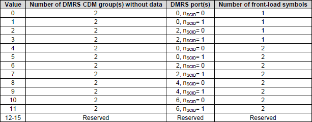
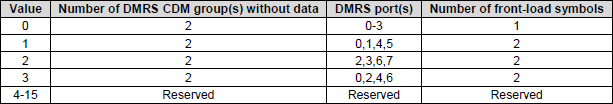
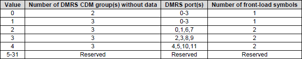
< 38.212 - Table 7.3.1.1.2-7: Antenna port(s), transform precoder is enabled, dmrs-Type=1, maxLength=2, except that dmrs-UplinkTransformPrecoding and tp-pi2BPSK are both configured and π/2-BPSK modulation is used >
Table 7.3.1.1.2-7 is used when transform precoding is enabled, DMRS Type 1 is configured, and maxLength is 2. This means the uplink uses DFT-s-OFDM and the DMRS can occupy two OFDM symbols instead of one. Because two DMRS symbols are available, the system can support more DMRS port combinations than in the maxLength 1 case.
The first thing this table shows is that the number of DMRS CDM groups without data is fixed at 2 for all valid entries. This means the UE must reserve two CDM groups for reference signals only. The purpose is to give the gNB a clean and reliable reference for channel estimation.
The next important field is the DMRS port. The table maps each DCI value to a specific DMRS port and scrambling identity. For the lower values, the UE uses DMRS port 0 or 2 with nSCID equal to 0 or 1. For the higher values, the table expands to include DMRS port 4 and 6. This is possible because maxLength 2 gives more time-domain room for orthogonal DMRS patterns.
Another important field is the number of front-load symbols. For values 0 to 3, the number of front-load symbols is 1. This means the DMRS occupies only one front-loaded symbol even though maxLength allows up to two symbols. For values 4 to 11, the number of front-load symbols becomes 2. This means the UE uses two front-loaded DMRS symbols, which allows more DMRS port choices.
So this table is basically a mapping between the DCI antenna-port field and three actual PHY settings. These are the DMRS port, the scrambling identity, and the number of front-load symbols. The gNB sends only a small index in DCI, and the UE uses this table to know exactly how to place the uplink reference signals.
At a high level, this table shows how NR expands DMRS flexibility when maxLength changes from 1 to 2. With one DMRS symbol, the number of possible reference-signal patterns is limited. With two DMRS symbols, more orthogonal DMRS port options become available, so the table becomes larger. This gives the network more flexibility in uplink channel estimation while still keeping the signaling compact.
< 38.212 - Table 7.3.1.1.2-8:Antenna port(s), transform precoder is disabled, dmrs-Type=1, maxLength=1,rank=1>
Table 7.3.1.1.2-8 is the basic antenna-port mapping table for uplink transmission when transform precoding is disabled, DMRS Type 1 is used, maxLength is 1, and the transmission rank is 1. In this case the uplink waveform is CP-OFDM, the UE sends only one layer, and the DMRS occupies only one OFDM symbol.
This table tells the UE how to interpret the Antenna Port field in DCI. The DCI does not directly carry the full DMRS configuration. Instead, it carries a small value, and this table converts that value into the actual DMRS port and the number of DMRS CDM groups without data.
For values 0 and 1, the number of DMRS CDM groups without data is 1. In these cases the UE uses DMRS port 0 or port 1. This is the simplest configuration. It uses one CDM group and one DMRS port, so the overhead is relatively small.
For values 2 to 5, the number of DMRS CDM groups without data becomes 2. In these cases the UE can use DMRS port 0, 1, 2, or 3. This gives more reference-signal separation capability, but it also reserves more resource elements for DMRS.
At a high level, this table shows a simple tradeoff between overhead and reference-signal flexibility. Lower values use fewer CDM resources and simpler DMRS port choices. Higher values reserve more CDM resources and allow more DMRS port options.
Since this table is for rank 1, it is only about selecting the DMRS reference structure for a single transmitted layer. It does not deal with multi-layer port combinations. So this is one of the simplest DMRS antenna-port tables in the uplink specification.
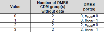
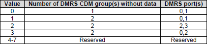
< 38.212 - Table 7.3.1.1.2-9:Antenna port(s), transform precoder is disabled, dmrs-Type=1, maxLength=1,rank= 2>
Table 7.3.1.1.2-9 defines the antenna-port mapping when transform precoding is disabled, DMRS Type 1 is used, maxLength is 1, and the transmission rank is 2. In this configuration the uplink waveform is CP-OFDM and the UE transmits two layers simultaneously.
The table shows how the Antenna Port field in DCI is translated into the actual DMRS configuration used for the uplink transmission. The DCI carries only a small value, and the UE uses this table to determine both the number of DMRS CDM groups without data and the specific DMRS port pair assigned to the two layers.
For value 0, the UE uses DMRS ports 0 and 1 with one CDM group without data. This is the simplest configuration and has the smallest reference signal overhead.
For value 1, the UE still uses ports 0 and 1, but the number of DMRS CDM groups without data increases to two. This gives better separation between reference signals but uses more resource elements for DMRS.
For value 2, the DMRS port pair changes to ports 2 and 3, again using two CDM groups without data. This provides another orthogonal reference-signal configuration for two-layer transmission.
For value 3, the UE uses ports 0 and 2 with two CDM groups without data. This provides a different spatial reference arrangement that can help the receiver separate the two layers depending on the channel conditions.
Values 4 through 7 are reserved and therefore not used for this configuration.
At a high level, this table shows how two-layer uplink transmissions select their reference-signal ports. Each entry defines a pair of DMRS ports corresponding to the two transmitted layers and specifies how many CDM groups must be reserved for reference signals. This allows the gNB to correctly estimate the channel for both layers and decode the spatially multiplexed uplink data.
< 38.212 - Table 7.3.1.1.2-10: Antenna port(s), transform precoder is disabled,dmrs-Type=1,maxLength=1,rank=3 >
Table 7.3.1.1.2-10 defines the antenna-port mapping when transform precoding is disabled, DMRS Type 1 is used, maxLength is 1, and the transmission rank is 3. In this configuration the uplink waveform is CP-OFDM and the UE transmits three layers at the same time.
This table shows how the Antenna Port field in DCI is interpreted to determine the DMRS configuration for the uplink transmission. Because three layers are transmitted, the gNB needs reference signals that correspond to three different DMRS ports.
In this case there is only one valid configuration. The DCI value 0 maps to DMRS ports 0, 1, and 2. The number of DMRS CDM groups without data is fixed at 2. This means two CDM groups are reserved for reference signals so that the gNB can reliably estimate the channel for the three transmitted layers.
All other values in the table are reserved. This means the DCI field effectively has only one usable entry for this specific configuration.
At a high level, this table shows that the DMRS configuration options become more limited as the transmission rank increases. When three layers are transmitted with a single DMRS symbol, there are fewer possible orthogonal reference-signal patterns available. Because of this limitation, the specification allows only one valid DMRS port combination for this case.
![]()
< 38.212 - Table 7.3.1.1.2-11: Antenna port(s), transform precoder is disabled, dmrs-Type=1,maxLength=1,rank= 4>
Table 7.3.1.1.2-11 defines the antenna-port mapping when transform precoding is disabled, DMRS Type 1 is used, maxLength is 1, and the transmission rank is 4. In this configuration the uplink waveform is CP-OFDM and the UE transmits four layers simultaneously.
The table explains how the Antenna Port field in DCI is translated into the DMRS configuration used for the uplink transmission. Because four layers are transmitted, the reference signals must cover four DMRS ports so that the gNB can estimate the channel for each layer.
There is only one valid entry in this table. When the DCI value is 0, the UE uses DMRS ports 0, 1, 2, and 3. The number of DMRS CDM groups without data is fixed at 2. This means two CDM groups are reserved for reference signals so the gNB can reliably estimate the channel for all four transmitted layers.
All other values are reserved and are not used for this configuration.
At a high level, this table shows that when the transmission rank reaches four layers and only one DMRS symbol is used, there is only one valid DMRS port configuration. The reference signals must occupy ports 0 through 3 so that each transmitted layer has a corresponding channel reference for decoding at the gNB.
![]()
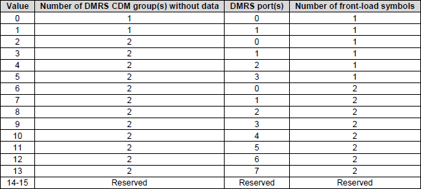
< 38.212 - Table 7.3.1.1.2-12: Antenna port(s), transform precoder is disabled, dmrs-Type=1, maxLength=2, rank=1>
Table 7.3.1.1.2-12 defines the antenna-port mapping when transform precoding is disabled, DMRS Type 1 is used, maxLength is 2, and the transmission rank is 1. In this case the uplink waveform is CP-OFDM, the UE transmits one layer, and the DMRS can occupy up to two OFDM symbols.
This table shows how the Antenna Port field in DCI is translated into three actual PHY settings. These are the number of DMRS CDM groups without data, the DMRS port, and the number of front-load symbols. So the DCI does not directly signal the full reference-signal pattern. Instead, it sends a small value, and the UE uses this table to determine the exact DMRS configuration.
For the lowest values, the number of front-load symbols is 1. In these cases the UE uses DMRS port 0 or 1 with either one or two CDM groups without data. This is the lower-overhead part of the table. It gives simple rank-1 reference-signal options while keeping the DMRS structure relatively compact.
As the values increase, the number of front-load symbols becomes 2. This means the UE now uses two front-loaded DMRS symbols instead of one. Because there is more time-domain space for DMRS, the table can support more DMRS port choices. That is why the valid DMRS ports expand from the earlier small set to ports 0 through 7.
The number of DMRS CDM groups without data is mostly 2 in this table, except for the first two entries where it is 1. This shows that once the configuration moves beyond the simplest cases, the specification reserves more resource elements for reference signals so that the gNB can obtain a cleaner channel estimate.
At a high level, this table shows how the DMRS configuration becomes more flexible when maxLength changes from 1 to 2. With only one DMRS symbol, the number of possible port choices is limited. With two DMRS symbols, more orthogonal reference-signal patterns become possible, so the table becomes larger and supports more DMRS ports. This gives the network more flexibility in configuring uplink channel estimation for single-layer CP-OFDM transmission.
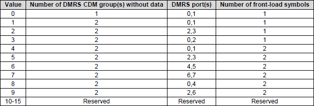
< 38.212 - Table 7.3.1.1.2-13: Antenna port(s), transform precoder is disabled, dmrs-Type=1, maxLength=2, rank=2>
Table 7.3.1.1.2-13 defines the antenna-port mapping when transform precoding is disabled, DMRS Type 1 is used, maxLength is 2, and the transmission rank is 2. In this configuration the uplink waveform is CP-OFDM and the UE transmits two layers simultaneously.
This table shows how the Antenna Port field in DCI is converted into the actual DMRS configuration used by the UE. The DCI value determines three things: the number of DMRS CDM groups without data, the pair of DMRS ports assigned to the two layers, and the number of front-load symbols used for DMRS.
For the first few values, the number of front-load symbols is 1. In these cases the UE uses only one DMRS symbol even though maxLength allows two. The DMRS port pairs include combinations such as ports 0 and 1, ports 2 and 3, or ports 0 and 2. These options allow the network to select different reference-signal structures depending on the channel conditions.
For the higher values, the number of front-load symbols becomes 2. This means the UE uses two DMRS symbols in the time domain. With two symbols available, the table supports additional DMRS port pairs such as 4 and 5, 6 and 7, 0 and 4, and 2 and 6. This expands the number of orthogonal reference-signal configurations that can be used for two-layer transmission.
The number of DMRS CDM groups without data is usually 2 in this table, except for the first entry where it is 1. Reserving two CDM groups allows the reference signals for both layers to remain distinguishable at the receiver.
At a high level, this table demonstrates how the DMRS configuration becomes more flexible when two DMRS symbols are available. The additional time-domain space allows more DMRS ports and more orthogonal reference-signal combinations. This helps the gNB estimate the channel for both layers more accurately during two-layer uplink spatial multiplexing.
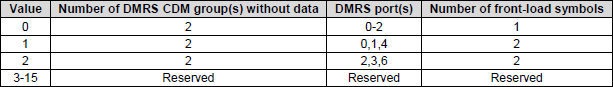
< 38.212 - Table 7.3.1.1.2-14: Antenna port(s), transform precoder is disabled, dmrs-Type=1, maxLength=2,rank=3>
Table 7.3.1.1.2-14 defines the antenna-port mapping when transform precoding is disabled, DMRS Type 1 is used, maxLength is 2, and the transmission rank is 3. In this configuration the uplink waveform is CP-OFDM and the UE transmits three layers simultaneously.
This table shows how the Antenna Port field in DCI determines the DMRS configuration used for the uplink transmission. The value carried in DCI is translated into three parameters: the number of DMRS CDM groups without data, the DMRS port set used for the three layers, and the number of front-load symbols.
For value 0, the number of front-load symbols is 1. The UE uses DMRS ports 0, 1, and 2, and the number of DMRS CDM groups without data is 2. This represents the simplest configuration for three-layer transmission with a single DMRS symbol.
For value 1, the number of front-load symbols becomes 2. The UE uses DMRS ports 0, 1, and 4, and the number of DMRS CDM groups without data remains 2. Using two front-loaded symbols allows additional DMRS port combinations beyond the basic set.
For value 2, the number of front-load symbols is also 2. In this case the UE uses DMRS ports 2, 3, and 6, again with two CDM groups without data.
All other values are reserved and therefore not used for this configuration.
At a high level, this table shows that when three layers are transmitted and two DMRS symbols are available, the specification allows only a small number of DMRS port combinations. These combinations provide enough orthogonality for channel estimation while keeping the signaling simple and controlled.
< 38.212 - Table 7.3.1.1.2-15: Antenna port(s), transform precoder is disabled, dmrs-Type=1, maxLength=2, rank=4>
Table 7.3.1.1.2-15 defines the antenna-port mapping when transform precoding is disabled, DMRS Type 1 is used, maxLength is 2, and the transmission rank is 4. In this configuration the uplink waveform is CP-OFDM and the UE transmits four layers simultaneously.
This table shows how the Antenna Port field in DCI is converted into the actual DMRS configuration for the uplink transmission. The DCI value determines three things. It determines the number of DMRS CDM groups without data, the set of DMRS ports assigned to the four layers, and the number of front-load symbols used for DMRS.
For value 0, the UE uses DMRS ports 0, 1, 2, and 3 with one front-load symbol. The number of DMRS CDM groups without data is 2. This is the most basic four-layer DMRS configuration in this table.
For value 1, the UE uses DMRS ports 0, 1, 4, and 5 with two front-load symbols. For value 2, the UE uses DMRS ports 2, 3, 6, and 7 with two front-load symbols. For value 3, the UE uses DMRS ports 0, 2, 4, and 6 with two front-load symbols. In all of these cases, the number of DMRS CDM groups without data remains 2.
The use of two front-load symbols allows the table to support additional DMRS port combinations beyond the basic 0 to 3 set. This gives the network more flexibility in arranging orthogonal reference signals for four-layer transmission. Since four layers are being transmitted, the gNB needs a reference-signal structure that can clearly distinguish all four layers during channel estimation.
All remaining values are reserved. This means only a small number of controlled DMRS port combinations are allowed for this configuration.
At a high level, this table shows the most expanded DMRS Type 1 configuration for maxLength equal to 2 and rank 4. Compared to the maxLength 1 case, the extra DMRS symbol allows more port combinations, so the network can choose from several valid reference-signal arrangements while still keeping the signaling compact and well-defined.
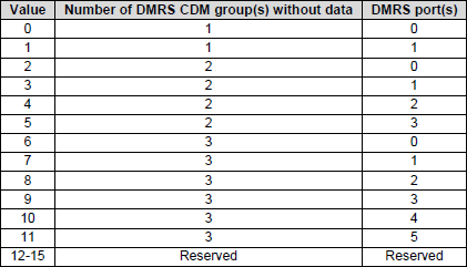
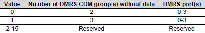
< 38.212 - Table 7.3.1.1.2-16: Antenna port(s), transform precoder is disabled, dmrs-Type=2, maxLength=1,rank=1>
Table 7.3.1.1.2-16 defines the antenna-port mapping when transform precoding is disabled, DMRS Type 2 is used, maxLength is 1, and the transmission rank is 1. In this configuration the uplink waveform is CP-OFDM and the UE transmits a single layer.
This table explains how the Antenna Port field in DCI is translated into the DMRS configuration used for the uplink transmission. The DCI value determines two parameters. It determines the number of DMRS CDM groups without data and the DMRS port used for the transmission.
For the first values, the number of DMRS CDM groups without data is 1. In these cases the UE uses DMRS port 0 or port 1. This represents the simplest reference-signal configuration with the smallest overhead.
For the next set of values, the number of CDM groups increases to 2. In these entries the UE can use DMRS ports 0, 1, 2, or 3. Reserving two CDM groups gives more orthogonality between reference signals and helps the gNB estimate the channel more reliably.
For the higher values, the number of CDM groups increases to 3. In these cases the UE can use DMRS ports 0 through 5. This is possible because DMRS Type 2 supports more ports than Type 1. The additional CDM groups provide further separation between reference signals and reduce interference when multiple transmissions are present.
Values 12 through 15 are reserved and are not used for this configuration.
At a high level, this table shows how DMRS Type 2 expands the reference-signal flexibility compared to DMRS Type 1. With Type 2, more CDM groups and more DMRS ports can be used, which allows the gNB to support more advanced uplink configurations while still maintaining reliable channel estimation.
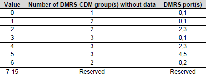
< 38.212 - Table 7.3.1.1.2-17:Antenna port(s), transform precoder is disabled, dmrs-Type=2, maxLength=1,rank=2>
Table 7.3.1.1.2-17 defines the antenna-port mapping when transform precoding is disabled, DMRS Type 2 is used, maxLength is 1, and the transmission rank is 2. In this configuration the uplink waveform is CP-OFDM and the UE transmits two layers simultaneously.
The table shows how the Antenna Port field in DCI is translated into the DMRS configuration used for the uplink transmission. The DCI value determines two parameters: the number of DMRS CDM groups without data and the pair of DMRS ports assigned to the two layers.
For value 0, the UE uses DMRS ports 0 and 1 with one CDM group without data. This is the simplest configuration and has the lowest reference-signal overhead.
For value 1, the UE still uses ports 0 and 1, but the number of CDM groups increases to two. This provides more separation between reference signals.
For value 2, the UE uses DMRS ports 2 and 3 with two CDM groups without data. This gives another orthogonal reference-signal configuration for two-layer transmission.
For values 3 and 4, the number of CDM groups increases to three while still using ports 0 and 1 or ports 2 and 3. Increasing the number of CDM groups improves orthogonality and channel estimation reliability.
For value 5, the UE uses ports 4 and 5 with three CDM groups without data. This takes advantage of the additional DMRS ports supported by Type 2 configurations.
For value 6, the UE uses ports 0 and 2 with two CDM groups without data. This provides a different spatial mapping for the two layers.
Values 7 through 15 are reserved and not used.
At a high level, this table shows how DMRS Type 2 allows more flexible reference-signal configurations for two-layer transmission. Compared with Type 1, it supports more DMRS ports and additional CDM groups, which helps the gNB perform accurate channel estimation when multiple layers are transmitted.
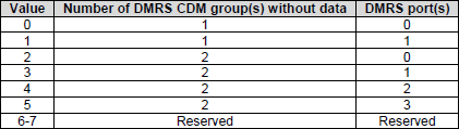
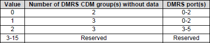
< 38.212 - Table 7.3.1.1.2-18:Antenna port(s), transform precoder is disabled, dmrs-Type=2, maxLength=1, rank=3>
Table 7.3.1.1.2-18 defines the antenna-port mapping when transform precoding is disabled, DMRS Type 2 is used, maxLength is 1, and the transmission rank is 3. In this configuration the uplink waveform is CP-OFDM and the UE transmits three layers at the same time.
This table shows how the Antenna Port field in DCI is translated into the DMRS configuration used for the uplink transmission. The DCI value determines the number of DMRS CDM groups without data and the set of DMRS ports assigned to the three layers.
For value 0, the UE uses DMRS ports 0, 1, and 2. The number of DMRS CDM groups without data is 2. This is the basic configuration for three-layer transmission with DMRS Type 2.
For value 1, the UE still uses DMRS ports 0, 1, and 2, but the number of CDM groups increases to 3. This provides stronger orthogonality between the reference signals and improves channel estimation performance.
For value 2, the UE uses DMRS ports 3, 4, and 5 with three CDM groups without data. This provides another orthogonal reference-signal configuration for three-layer transmission.
Values 3 through 15 are reserved and not used for this configuration.
At a high level, this table shows how DMRS Type 2 supports different reference-signal configurations for three-layer uplink transmission. By adjusting the number of CDM groups and selecting different DMRS port sets, the network can optimize channel estimation for spatial multiplexing with three layers.
< 38.212 - Table 7.3.1.1.2-19:Antenna port(s), transform precoder is disabled, dmrs-Type=2, maxLength=1, rank=4>
Table 7.3.1.1.2-19 defines the antenna-port mapping for one of the highest uplink MIMO cases in NR. It is used when transform precoding is disabled, DMRS Type 2 is configured, maxLength is 1, and the UE transmits at rank 4. In this case the UE is sending four independent layers at the same time, so the reference-signal structure must allow the gNB to distinguish all four layers clearly.
Because the transmission rank is 4, the DMRS port set is fixed to ports 0, 1, 2, and 3. This means each layer is associated with one of these orthogonal DMRS ports. The table does not offer different port combinations because, at this rank and with only one DMRS symbol, the available orthogonal choices are already very limited.
The only real difference between the valid entries is the number of DMRS CDM groups without data. One case uses 2 CDM groups, and the other uses 3 CDM groups. When more CDM groups are reserved without data, more resource elements are protected for reference signals. This reduces data efficiency somewhat, but it improves separation between reference signals and can help the gNB perform more reliable channel estimation, especially in more crowded or interference-sensitive conditions.
This table is also a good example of efficient DCI design. Since there are only two valid configurations, the Antenna Port field needs only a very small number of bits. The UE only needs to distinguish between the two CDM-group choices, while the DMRS port set itself remains the same.
At a high level, this table shows that as the uplink rank becomes very high, the freedom in port selection becomes smaller. The main focus is no longer choosing among many different DMRS port sets. Instead, the focus shifts to controlling how much DMRS resource overhead is allocated so that all four layers can be decoded reliably. In other words, for rank 4 uplink with DMRS Type 2 and maxLength 1, the port assignment is fixed, and the network mainly adjusts the reference-signal protection level through the CDM-group setting.
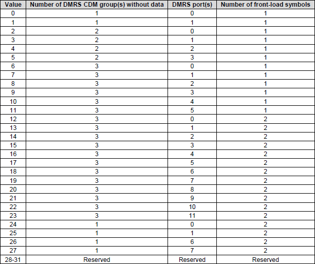
< 38.212 - Table 7.3.1.1.2-20:Antenna port(s), transform precoder is disabled, dmrs-Type=2, maxLength=2,rank=1>
Table 7.3.1.1.2-20 defines the Antenna Port field for a single-layer uplink transmission when transform precoding is disabled, DMRS Type 2 is used, and maxLength is 2. In this case the uplink waveform is CP-OFDM, the UE sends only one layer, and the DMRS can use up to two OFDM symbols. This makes the table larger and more flexible than the simpler rank-1 tables.
The main reason this table is more complex is that DMRS Type 2 supports a larger number of DMRS ports. With this configuration, the network can choose from a wide set of reference-signal patterns, which is useful in higher-capacity scenarios such as dense scheduling or multi-user operation. Even though the UE is sending only one layer, the DMRS configuration can still vary a lot depending on how the gNB wants to arrange channel estimation and interference separation.
One important part of the table is the number of front-load symbols. Some entries use one DMRS front-load symbol, while others use two. When only one symbol is used, the overhead is smaller, so it is more efficient. When two symbols are used, the DMRS has more time-domain space, so more orthogonal port configurations become possible. This gives the network more flexibility in separating reference signals.
Another important field is the number of DMRS CDM groups without data. This tells the UE how many resource elements must be reserved only for DMRS and not used for PUSCH data. As this number increases, more space is protected for reference signals. That reduces efficiency a little, but it improves the ability of the gNB to distinguish different DMRS patterns and perform cleaner channel estimation.
The DMRS port range in this table also becomes much larger than in earlier rank-1 tables. In the more advanced entries, the table can map the DCI value to a wide port range, including ports up to 11. This shows that even for single-layer transmission, the reference-signal design can be quite rich when DMRS Type 2 and maxLength 2 are used.
At a high level, this table shows how NR supports high-capacity uplink reference-signal configuration even for Rank 1 transmission. The UE still sends only one data layer, but the gNB can place that layer into a carefully chosen DMRS port and CDM structure so that it can coexist efficiently with other transmissions in the cell. This table is therefore more about flexible channel-estimation design than about increasing the number of transmitted layers.
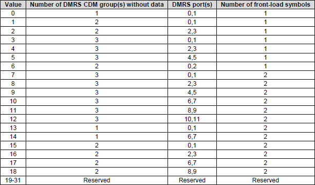
< 38.212 - Table 7.3.1.1.2-21:Antenna port(s), transform precoder is disabled,dmrs-Type=2,maxLength=2,rank=2>
Table 7.3.1.1.2-21 defines the antenna-port mapping for rank 2 uplink transmission when transform precoding is disabled, DMRS Type 2 is used, and maxLength is 2. In this case the UE sends two layers, and the DCI antenna-port field tells the UE which DMRS port pair to use, how many CDM groups are reserved without data, and whether one or two front-load symbols are used.
Because the transmission rank is 2, the DMRS ports are assigned as pairs. Each pair corresponds to the two transmitted layers. Many of these pairs appear as adjacent ports such as 0 and 1, 2 and 3, or 4 and 5. This makes sense because the two layers need a structured and orthogonal reference-signal arrangement so the gNB can estimate both channels and separate the two streams reliably.
One important dimension in this table is the number of front-load symbols. Some entries use one front-load symbol, while others use two. When one symbol is used, the overhead is smaller and the configuration is more efficient. When two symbols are used, more orthogonal reference-signal patterns become possible, which improves flexibility and can support more demanding channel conditions.
Another important dimension is the number of DMRS CDM groups without data. When this number is small, less resource is reserved for DMRS, so the overhead is lower. When the number becomes larger, more resource elements are protected for reference signals. This reduces data efficiency somewhat, but it improves separability and gives the network more room to organize multiple reference-signal structures.
This table is basically the rank 2 extension of the richer DMRS Type 2 and maxLength 2 framework. Compared to the rank 1 case, the UE now needs a pair of DMRS ports instead of a single port. Compared to the maxLength 1 case, the use of two DMRS symbols allows a larger set of valid port combinations and more flexible reference-signal design.
At a high level, this table shows how NR supports dual-layer uplink transmission in a high-capacity reference-signal framework. The gNB can use the DCI field to quickly select the DMRS port pair, the CDM overhead level, and the front-load symbol configuration. This allows the network to balance efficiency, channel-estimation quality, and multiplexing flexibility while supporting rank 2 uplink transmission.
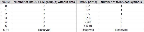
< 38.212 - Table 7.3.1.1.2-22: Antenna port(s), transform precoder is disabled, dmrs-Type=2, maxLength=2,rank=3>
Table 7.3.1.1.2-22 defines the antenna-port mapping for rank 3 uplink transmission when transform precoding is disabled, DMRS Type 2 is used, and maxLength is 2. In this case the UE transmits three layers, so the DCI antenna-port field must identify a set of three DMRS ports, the number of CDM groups without data, and the number of front-load symbols.
Because the transmission rank is 3, each valid entry gives a triplet of DMRS ports. In the simpler cases, the triplets are grouped in a compact way such as 0,1,2 or 3,4,5. These are the basic rank 3 reference-signal groupings. They are used when one front-load symbol is enough.
When two front-load symbols are used, the table can support wider port combinations such as 0,1,6 or 2,3,8. This is possible because two DMRS symbols give more time-domain freedom, so additional ports can remain orthogonal. In other words, maxLength 2 allows the network to build richer rank 3 DMRS patterns than maxLength 1.
Another important point is the number of DMRS CDM groups without data. For rank 3, this is usually kept at 3 except for the most basic entry. This means more resource elements are reserved only for DMRS. The overhead becomes larger, but the benefit is better separation between the three reference signals and better channel estimation at the gNB.
This table also shows that as the transmission rank increases, the number of valid DMRS choices becomes smaller. For rank 1 there are many possible configurations. For rank 2 there are fewer. For rank 3 the options become even more restricted. This is because higher-rank transmission needs stricter orthogonality and more controlled reference-signal patterns.
At a high level, this table is the rank 3 version of the high-capacity DMRS Type 2 framework. It shows how the network balances three things at the same time. It chooses the DMRS port triplet, it chooses how much reference-signal overhead to reserve through the CDM-group setting, and it chooses whether one or two front-load symbols are needed. This allows the gNB to support three-layer uplink transmission while keeping the DMRS structure stable enough for reliable decoding.
< 38.212 - Table 7.3.1.1.2-23:Antenna port(s), transform precoder is disabled, dmrs-Type=2, maxLength=2,rank=4>
Table 7.3.1.1.2-23 defines the antenna-port mapping for rank 4 uplink transmission when transform precoding is disabled, DMRS Type 2 is used, and maxLength is 2. In this configuration the UE transmits four layers simultaneously, which is the highest standard uplink rank for single-user MIMO.
Since four layers are transmitted, each valid entry assigns a group of four DMRS ports. These ports provide the reference signals that allow the gNB to estimate the channel for each of the four layers and separate them during decoding.
For the simplest cases, the port set is 0, 1, 2, and 3. These ports are arranged so that the reference signals remain orthogonal within a single DMRS symbol. In these cases the number of front-load symbols is one. This configuration has lower overhead and is typically used when the radio channel is stable.
In the more advanced entries, the number of front-load symbols becomes two. When two DMRS symbols are used, the table can support additional port clusters such as 0,1,6,7 or 2,3,8,9. These larger port indices rely on time-domain separation in addition to frequency and code-domain separation. Using two symbols makes it easier to maintain orthogonality between reference signals when more ports are involved.
Another important parameter in the table is the number of DMRS CDM groups without data. For most entries this value is three. Reserving three CDM groups means that more resource elements are dedicated to reference signals. This increases overhead slightly, but it improves the clarity of the reference signals and helps the gNB perform accurate channel estimation when four layers are transmitted.
This table also shows that as the transmission rank increases, the system must carefully control the DMRS structure. High-rank transmission requires strong orthogonality between reference signals, and that often means reserving more resource elements or using additional DMRS symbols.
At a high level, this table represents the most advanced DMRS configuration for uplink spatial multiplexing. It defines how four-layer transmission can be supported using DMRS Type 2 with two reference-signal symbols. By selecting different port clusters, CDM-group settings, and front-load symbol configurations, the network can balance throughput, interference protection, and channel-estimation accuracy for rank 4 uplink transmission.
MIMO Configuration Table : Precoding Matrix
These tables in TS 38.211 are the actual mathematical engine of uplink precoding. The tables in TS 38.212 tell the UE which TPMI to use. These tables in TS 38.211 tell the UE what that TPMI really means in terms of the precoding matrix W.
At the PHY level, precoding means mapping v transmission layers onto P antenna ports. The UE does this by matrix multiplication. The input vector x is the layer data. The matrix W is the precoding matrix. The output vector y is the signal that goes to the antenna ports. So these tables define the real complex-number coefficients that shape the transmitted signal.
The tables are organized by three factors. One is the number of layers. Another is the number of antenna ports. The other is whether transform precoding is enabled or disabled. Based on these conditions, the UE selects the proper table and then selects the proper matrix inside that table using TPMI.
These matrices also reflect different hardware capabilities through the codebook subset concept. In fully coherent operation, the matrix can have non-zero values across all antenna ports, so the UE can control phase and amplitude across all ports together. In partial coherent operation, only some antenna groups are jointly controlled. In non-coherent operation, the mapping is much simpler, and each layer is mainly tied to a specific antenna port without strict phase alignment across all ports.
At a high level, these TS 38.211 tables are the final execution step of uplink MIMO. TS 38.212 decides which TPMI index is selected from DCI. TS 38.211 converts that TPMI into the actual precoding matrix. Then the UE applies that matrix to the data symbols and sends the resulting signals through the antenna ports. This is where the control decision becomes real PHY transmission.
Tables in this section shows Precoding Matrix for PUSCH for various situations. Which one of these tables to use is determined by RRC Configuration and which row(element) of the selected table is used is associated with Precoding information and number of layers in DCI 0_1. (i.e, the specific TMPI index is indirectly determined by Precoding Information and number of layers field).
< 38.211 v15.5 - Table 6.3.1.5-1: Precoding matrix W for single-layer transmission using two antenna ports. >
This table defines the real precoding vectors used when a 2-port UE transmits one layer. The earlier 38.212 tables were about how to decode the control field in DCI. This table is different. It shows the actual complex-number vector that the UE applies to the data symbol before sending it through the antenna ports.
Because this is Rank 1 on 2 antenna ports, each precoding matrix is a 2 x 1 vector. The first element is for antenna port 0. The second element is for antenna port 1. The factor 1 over square root of 2 is used for normalization. This keeps the total transmit power consistent even when both antenna ports are active.
This table clearly shows the difference between non-coherent transmission and coherent transmission. For TPMI 0 and TPMI 1, only one antenna port is active. One vector sends the symbol only through antenna port 0. The other sends it only through antenna port 1. This is the simplest case. It does not require phase alignment between the two ports.
For the other TPMI values, both antenna ports are active at the same time. In these cases, the UE sends the same layer through both ports but with a specific phase relationship. Some vectors use plus or minus one. This means the two ports are either in phase or 180 degrees out of phase. Other vectors use j or minus j. This means the second port has a 90 degree or 270 degree phase shift relative to the first port.
This phase relationship is the key point of precoding. The UE is not just turning antennas on and off. It is controlling the phase of the transmitted signal across the two antenna ports. This changes how the radio waves combine in space. As a result, the UE can steer the signal more effectively toward the gNB.
So when the DCI and 38.212 table tell the UE to use a certain TPMI, the UE finally comes to this table and gets the actual vector. Then it applies that vector to the data symbol and generates the per-port transmission signal.
At a high level, this table shows the physical meaning of uplink precoding. MIMO is not only about having multiple antennas. It is about using complex-number weights across those antennas so that the transmitted energy combines in a more useful direction. This is where the uplink control decision becomes real PHY-layer signal shaping.
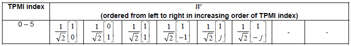
< 38.211 v15.5 - Table 6.3.1.5-2: Precoding matrix W for single-layer transmission using four antenna ports with transform precoding enabled. >
Table 6.3.1.5-2 defines the precoding vectors used when a UE transmits a single layer using four antenna ports with transform precoding enabled. In this situation the uplink waveform is DFT-s-OFDM, which is commonly used for better power efficiency and lower peak-to-average power ratio.
Since the transmission rank is one and there are four antenna ports, each precoding matrix is a 4 × 1 column vector. Each element of the vector corresponds to one antenna port. The first element controls antenna port 0, the second controls antenna port 1, the third controls antenna port 2, and the fourth controls antenna port 3. These elements are complex numbers that determine how the same data symbol is distributed across the four antennas.
The scaling factor of one half is used to normalize the total transmission power. Even when multiple antenna ports transmit simultaneously, the total radiated power remains consistent.
The different TPMI indices correspond to different beam directions created by changing the phase relationships among the four antenna ports. Some vectors activate only a subset of antenna ports, while others activate all four ports together. The elements may include values such as 1, −1, j, or −j. These values represent phase shifts between the antennas. A value of −1 means a 180-degree phase shift, while j and −j represent 90-degree and 270-degree phase shifts. By carefully selecting these phase offsets, the UE can shape the transmitted wavefront so that energy combines constructively toward the base station.
Because transform precoding is enabled, the design of these vectors also considers the single-carrier nature of DFT-s-OFDM. The vectors are chosen so that the resulting signal maintains a low PAPR while still enabling beam steering and antenna diversity.
At a high level, this table provides the physical beamforming vectors for a four-port UE operating in single-layer uplink transmission with transform precoding. After the UE receives a TPMI value through the DCI and interprets it using the 38.212 tables, it comes to this table to retrieve the actual precoding vector. That vector is then applied to the data symbols so that the same layer is transmitted across the four antenna ports with the specific amplitude and phase relationships defined by the vector.

< 38.211 v15.5 - Table 6.3.1.5-3: Precoding matrix W for single-layer transmission using four antenna ports with transform precoding disabled. >
Table 6.3.1.5-3 defines the precoding vectors used when a UE transmits a single layer using four antenna ports with transform precoding disabled. In this case the uplink waveform is CP-OFDM. This mode is typically used when the system focuses on higher throughput and more flexible MIMO operation.
Because the transmission rank is one and there are four antenna ports, each precoding matrix in this table is a 4 × 1 vector. Each element of the vector corresponds to one antenna port. The first element controls antenna port 0, the second controls port 1, the third controls port 2, and the fourth controls port 3. These values determine how the same data symbol is transmitted across the four antennas.
The scaling factor of one half is again used to normalize the total transmit power. Even if several antenna ports are active at the same time, the total radiated power remains constant.
Each TPMI index represents a different beamforming direction created by adjusting the phase relationships between the antenna ports. The vector elements include values such as 1, −1, j, and −j. These correspond to phase shifts between antennas. A value of −1 represents a 180-degree phase shift, while j and −j represent 90-degree and 270-degree phase shifts. By changing these phase offsets across the four ports, the UE can steer the transmitted signal toward the gNB more effectively.
Compared with the transform-precoded version, this table is optimized for CP-OFDM operation. Since CP-OFDM does not impose the same constraints as DFT-s-OFDM, the precoding vectors can focus more on spatial beamforming flexibility rather than maintaining low PAPR characteristics.
At a high level, this table provides the beamforming vectors for single-layer uplink transmission on a four-port UE when transform precoding is disabled. After the UE determines the TPMI value from the DCI and the corresponding decoding table in TS 38.212, it retrieves the matching vector from this table and applies it to the data symbols. The resulting weighted signals are then transmitted through the four antenna ports with the phase and amplitude relationships defined by the vector.
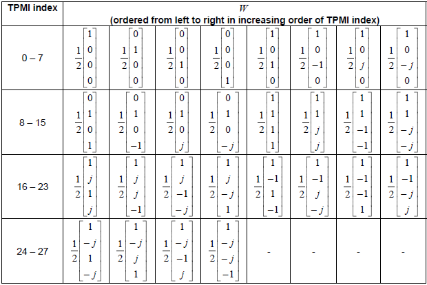
< 38.211 v15.5 - Table 6.3.1.5-4: Precoding matrix W for two-layer transmission using two antenna ports with transform precoding disabled. >
This table defines the actual precoding matrices for Rank 2 transmission with 2 antenna ports. In this case, the UE is not sending one layer anymore. It is sending two independent layers at the same time. This is the basic form of uplink spatial multiplexing.
Since there are 2 layers and 2 antenna ports, each precoding matrix is a 2 x 2 matrix. The first column shows how Layer 1 is mapped to the two antenna ports. The second column shows how Layer 2 is mapped to the two antenna ports. So this table tells the UE how to convert two input streams into two antenna-port signals.
The simplest case is TPMI 0. In this case, the matrix is basically an identity-type mapping with scaling. One layer goes to one antenna port, and the other layer goes to the other antenna port. This is the most straightforward mapping. It does not require strong coordination between the two ports, so it is the simplest and safest way to support Rank 2 transmission.
The other TPMI values are more advanced. In those cases, both layers are mixed across both antenna ports. The matrix entries include values such as -1 or j. These values create phase differences between the signals. This helps the receiver separate the two layers more effectively under different channel conditions. So these matrices do not just split layers across antennas. They also shape the phase relationship between them.
The scaling factor is also important. It keeps the total transmit power under control. When one antenna carries only one layer, the scaling can be larger. When both antennas carry combinations of both layers, the signal amplitude must be reduced more so that the total power stays within the allowed limit.
At a high level, this table shows the difference between beamforming-oriented Rank 1 transmission and throughput-oriented Rank 2 transmission. In Rank 1, the main goal is to steer one strong stream. In Rank 2, the main goal is to send two streams at the same time while keeping them distinguishable at the receiver.
So this table is the physical-layer foundation for 2-port uplink spatial multiplexing. After the UE gets the TPMI from DCI through the related 38.212 table, it uses this table to find the actual 2 x 2 matrix. Then it applies that matrix to the two layer symbols and generates the two antenna-port signals for transmission.
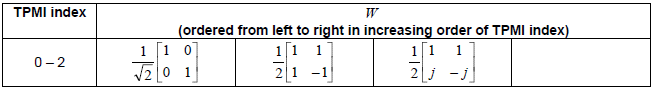
< 38.211 v15.5 - Table 6.3.1.5-5: Precoding matrix W for two-layer transmission using four antenna ports with transform precoding disabled. >
Table 6.3.1.5-5 defines the precoding matrices used when a UE transmits two layers using four antenna ports with transform precoding disabled. In this case the uplink waveform is CP-OFDM, and the UE sends two independent data streams at the same time.
Since there are two layers and four antenna ports, each precoding matrix is a 4 by 2 matrix. The first column describes how Layer 1 is mapped to the four antenna ports. The second column describes how Layer 2 is mapped to the four antenna ports. The UE multiplies this matrix with the two-layer symbol vector to produce four antenna-port signals.
The scaling factors such as 1/2 or 1 divided by 2 square root of 2 are used to keep the total transmit power constant. When several antenna ports carry combinations of the same layers, the signal amplitude must be scaled down so that the total radiated power stays within the allowed limit.
Each TPMI index corresponds to a different spatial mapping pattern. Some matrices map each layer mainly to different antenna ports or antenna groups. Other matrices mix both layers across all four antenna ports using phase rotations such as -1, j, or -j. These phase offsets change the spatial characteristics of the transmitted signal and help the receiver separate the two layers in different propagation environments.
The early TPMI entries represent simpler mappings where layers are assigned to different antenna pairs. As the TPMI index increases, the matrices use more complex combinations of antennas and phase shifts. These more advanced mappings provide better spatial diversity and improve the ability of the receiver to distinguish the two layers.
At a high level, this table defines how two independent data streams are distributed across four antenna ports during uplink spatial multiplexing. After the UE receives the TPMI index through DCI and decodes it using the tables in TS 38.212, it retrieves the corresponding matrix from this table and applies it to the two-layer data symbols before transmission.
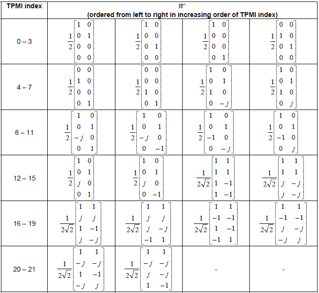
< 38.211 v15.5 - Table 6.3.1.5-6: Precoding matrix W for three-layer transmission using four antenna ports with transform precoding disabled. >
Table 6.3.1.5-6 defines the precoding matrices used when a UE transmits three layers using four antenna ports with transform precoding disabled. In this case the uplink waveform is CP-OFDM, and the UE sends three independent data streams at the same time.
Since there are three layers and four antenna ports, each precoding matrix is a 4 by 3 matrix. Each column represents one transmission layer. The first column maps Layer 1 to the four antenna ports, the second column maps Layer 2, and the third column maps Layer 3. The UE applies this matrix to the three-layer symbol vector to generate four antenna-port signals.
The first set of TPMI entries uses simpler structures with a scaling factor of 1/2. In these cases, the three layers are mapped more directly onto different antenna ports, with one row often left as zero or with a simple sign change. These matrices are easier to understand because they look like an extension of lower-rank mapping. They mainly distribute the three layers across the four available ports in a straightforward way.
The later TPMI entries use a scaling factor of 1 divided by 2 square root of 3. These matrices are more advanced because all antenna ports participate and the layers are mixed more evenly across the ports. The entries include values such as 1, -1, j, and -j. These phase terms create different spatial signatures for the three layers and help the receiver separate them more effectively.
The scaling factors are important because they keep the total transmit power under control. When more antenna ports actively carry combinations of multiple layers, the signal amplitude must be reduced so that the total transmitted power remains within the allowed limit.
At a high level, this table shows how three-layer uplink spatial multiplexing is implemented on a four-port UE. Compared to Rank 2, the matrix is larger and the mapping is more complex because the UE must keep three simultaneous layers distinguishable while still using only four antenna ports. After the UE gets the TPMI from DCI and decodes it through the related tables in TS 38.212, it uses this table to obtain the actual 4 by 3 precoding matrix and applies it to the three-layer data symbols before transmission.
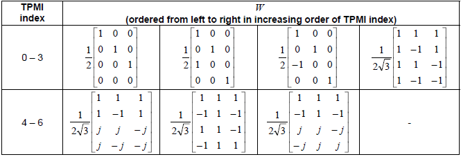
< 38.211 v15.5 - Table 6.3.1.5-7: Precoding matrix W for four-layer transmission using four antenna ports with transform precoding disabled. >
Table 6.3.1.5-7 defines the precoding matrices used when a UE transmits four layers using four antenna ports with transform precoding disabled. In this configuration the uplink waveform is CP-OFDM and the UE sends four independent data streams at the same time.
Since there are four layers and four antenna ports, each precoding matrix is a 4 by 4 matrix. Each column corresponds to one transmission layer. The first column maps Layer 1 to the four antenna ports, the second column maps Layer 2, the third column maps Layer 3, and the fourth column maps Layer 4. The UE multiplies this matrix with the four-layer symbol vector to generate the four antenna-port signals that will be transmitted.
The first TPMI entry is the simplest mapping. It is essentially a scaled identity matrix, where each layer is mapped directly to one antenna port. This is the most straightforward spatial multiplexing case because each antenna carries a separate layer without mixing with the others.
The following TPMI entries introduce mixing between the layers across multiple antenna ports. These matrices use combinations of values such as 1, −1, j, and −j. These phase rotations create different spatial signatures for each layer so that the receiver can separate them even when the radio channel introduces reflections and interference.
The scaling factors such as 1/2, 1 divided by 2 square root of 2, or 1/4 are used to normalize the transmit power. When multiple antenna ports carry combinations of several layers, the signal amplitudes must be reduced so that the total transmitted power remains constant.
As the TPMI index increases, the matrices become more complex and involve all antenna ports with different phase relationships. These matrices provide better spatial diversity and help the receiver distinguish the four layers in different channel conditions.
At a high level, this table represents the maximum spatial multiplexing configuration for a four-port UE. All four layers are transmitted simultaneously using four antenna ports. After the UE receives the TPMI value from the DCI and interprets it through the related tables in TS 38.212, it retrieves the corresponding 4 by 4 precoding matrix from this table and applies it to the four-layer data symbols before transmission.
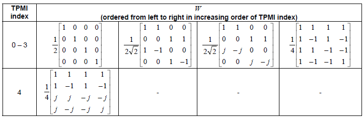
Examples
Example 01 : UL 2x2 MIMO
: This example is from the test with Amarisoft Callbox(gNB) and Amarisoft UEsim
|
< RRC Setup > : Full contents of the message is here. |
{
message c1: rrcSetup: {
...
spCellConfig {
spCellConfigDedicated {
initialDownlinkBWP {
...
uplinkConfig {
initialUplinkBWP {
...
pusch-Config setup: {
txConfig codebook,
dmrs-UplinkForPUSCH-MappingTypeA setup: {
dmrs-AdditionalPosition pos1,
transformPrecodingDisabled {
}
},
maxLength is not present, it mean maxLength is len1
pusch-PowerControl {
msg3-Alpha alpha1,
p0-NominalWithoutGrant -84,
p0-AlphaSets {
{
p0-PUSCH-AlphaSetId 0,
p0 0,
alpha alpha1
}
},
pathlossReferenceRSToAddModList {
{
pusch-PathlossReferenceRS-Id 0,
referenceSignal ssb-Index: 0
}
},
sri-PUSCH-MappingToAddModList {
{
sri-PUSCH-PowerControlId 0,
sri-PUSCH-PathlossReferenceRS-Id 0,
sri-P0-PUSCH-AlphaSetId 0,
sri-PUSCH-ClosedLoopIndex i0
}
}
},
resourceAllocation resourceAllocationType1,
codebookSubset nonCoherent,
maxRank 2,
uci-OnPUSCH setup: {
betaOffsets semiStatic: {
betaOffsetACK-Index1 9,
betaOffsetACK-Index2 9,
betaOffsetACK-Index3 9,
betaOffsetCSI-Part1-Index1 7,
betaOffsetCSI-Part1-Index2 7,
betaOffsetCSI-Part2-Index1 7,
betaOffsetCSI-Part2-Index2 7
},
scaling f1
}
},
srs-Config setup: {
srs-ResourceSetToAddModList {
{
srs-ResourceSetId 0,
srs-ResourceIdList {
0
},
resourceType periodic: {
},
usage codebook,
p0 -84,
pathlossReferenceRS ssb-Index: 0
}
},
srs-ResourceToAddModList {
{
srs-ResourceId 0,
nrofSRS-Ports ports2,
transmissionComb n2: {
combOffset-n2 0,
cyclicShift-n2 0
},
resourceMapping {
startPosition 1,
nrofSymbols n1,
repetitionFactor n1
},
freqDomainPosition 0,
freqDomainShift 5,
freqHopping {
c-SRS 11,
b-SRS 3,
b-hop 0
},
groupOrSequenceHopping neither,
resourceType periodic: {
periodicityAndOffset-p sl80: 7
},
sequenceId 500
}
}
}
},
firstActiveUplinkBWP-Id 0,
pusch-ServingCellConfig setup: {
}
},
...
|
< DCI 0_1 > |
Following is an example of DCI 0_1 transmitted by the gNB. In this case (based on RRC configuration shown above : 2 antenna ports, codebookSubset = nonCoherent, transform precoder = disabled, ul-FullPowerTransmission = not configured), precoding_info indicates the index in 38.212 - Table 7.3.1.1.2-4 and antenna_ports indicates the index in 38.212 - Table 7.3.1.1.2-9
Message: ss_id=2 cce_index=2 al=2 dci=0_1 k2=7
Data:
rb_alloc=0x12f
time_domain_rsc=0
mcs=2
ndi=1
rv_idx=0
harq_process=0
dai=3
tpc_command=1
srs_request=0
dmrs_seq_init=0
ul_sch_indicator=1
Example 02 : UL 4x4 MIMO
: This example is from the test with Amarisoft Callbox(gNB) and Amarisoft UEsim
|
< RRC Setup > : Full contents of the message is here. |
{
message c1: rrcSetup: {
rrc-TransactionIdentifier 0,
...
spCellConfig {
spCellConfigDedicated {
...
uplinkConfig {
initialUplinkBWP {
...
pusch-Config setup: {
txConfig codebook,
dmrs-UplinkForPUSCH-MappingTypeA setup: {
dmrs-AdditionalPosition pos1,
transformPrecodingDisabled {
}
maxLength is not present, it mean maxLength is len1
},
pusch-PowerControl {
msg3-Alpha alpha1,
p0-NominalWithoutGrant -84,
p0-AlphaSets {
{
p0-PUSCH-AlphaSetId 0,
p0 0,
alpha alpha1
}
},
pathlossReferenceRSToAddModList {
{
pusch-PathlossReferenceRS-Id 0,
referenceSignal ssb-Index: 0
}
},
sri-PUSCH-MappingToAddModList {
{
sri-PUSCH-PowerControlId 0,
sri-PUSCH-PathlossReferenceRS-Id 0,
sri-P0-PUSCH-AlphaSetId 0,
sri-PUSCH-ClosedLoopIndex i0
}
}
},
resourceAllocation resourceAllocationType1,
codebookSubset nonCoherent,
maxRank 4,
uci-OnPUSCH setup: {
betaOffsets semiStatic: {
betaOffsetACK-Index1 9,
betaOffsetACK-Index2 9,
betaOffsetACK-Index3 9,
betaOffsetCSI-Part1-Index1 7,
betaOffsetCSI-Part1-Index2 7,
betaOffsetCSI-Part2-Index1 7,
betaOffsetCSI-Part2-Index2 7
},
scaling f1
}
},
srs-Config setup: {
srs-ResourceSetToAddModList {
{
srs-ResourceSetId 0,
srs-ResourceIdList {
0
},
resourceType periodic: {
},
usage codebook,
p0 -84,
pathlossReferenceRS ssb-Index: 0
}
},
srs-ResourceToAddModList {
{
srs-ResourceId 0,
nrofSRS-Ports ports4,
transmissionComb n2: {
combOffset-n2 0,
cyclicShift-n2 2
},
resourceMapping {
startPosition 1,
nrofSymbols n1,
repetitionFactor n1
},
freqDomainPosition 0,
freqDomainShift 5,
freqHopping {
c-SRS 11,
b-SRS 3,
b-hop 0
},
groupOrSequenceHopping neither,
resourceType periodic: {
periodicityAndOffset-p sl80: 7
},
sequenceId 500
}
}
}
},
firstActiveUplinkBWP-Id 0,
pusch-ServingCellConfig setup: {
}
},
|
< DCI 0_1 > |
Following is an example of DCI 0_1 transmitted by the gNB. In this case (based on RRC configuration shown above : 2 antenna ports, codebookSubset = nonCoherent, transform precoder = disabled, ul-FullPowerTransmission = not configured), precoding_info indicates the index in 38.212 - Table 7.3.1.1.2-2 and antenna_ports indicates the index in 38.212 - Table 7.3.1.1.2-11
Message: ss_id=2 cce_index=2 al=2 dci=0_1 k2=7
Data:
rb_alloc=0x12f
time_domain_rsc=0
mcs=2
ndi=1
rv_idx=0
harq_process=2
dai=0
tpc_command=1
srs_request=0
dmrs_seq_init=0
ul_sch_indicator=1
Reference