I assume that most of the readers are already familiar with the basic concept of MIMO from LTE MIMO. In 5G/NR, we will use a very special types of MIMO called Massive MIMO to implement both sptial multiplexing(MIMO) and BeamForming.
In this page, I will describe mostly about 3GPP details on how the MIMO is operated in NR.
- How MIMO is configured ?
- MIMO Configuration Table : Antenna Port Configuration
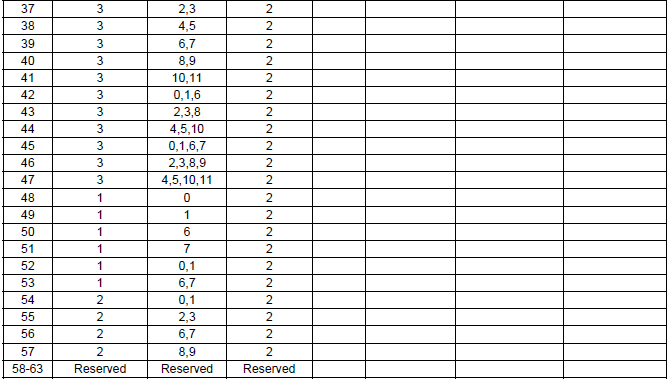
- Table 7.3.1.2.2-1: Antenna port(s) (1000 + DMRS port), dmrs-Type=1, maxLength=1
- Table 7.3.1.2.2-2: Antenna port(s) (1000 + DMRS port), dmrs-Type=1, maxLength=2
- Table 7.3.1.2.2-3: Antenna port(s) (1000 + DMRS port), dmrs-Type=2, maxLength=1
- Table 7.3.1.2.2-4: Antenna port(s) (1000 + DMRS port), dmrs-Type=2, maxLength=2
- Example : RRC IEs for Table Selection and DCI for Port Selection
- DMRS Pattern : Table 7.3.1.2.2-1
- DMRS Pattern : Table 7.3.1.2.2-2
- DMRS Pattern : Table 7.3.1.2.2-3
- DMRS Pattern : Table 7.3.1.2.2-4
- Reference
How MIMO is configured ?
The major factors for MIMO configuration is the number of antenna and layers. In LTE, these factors are specified explicitely by RRC message (RRC Connection Setup or RRCConnectionSetupReconfiguration). However, in NR there is no explicit RRC parameter for the number of Antenna and the number of layers. In stead, both UE and gNB carries a few predefined tables defining the number of antenna port and layers.
Now you would have a few questions. Out of these multiple predefiend table, how a UE figure out which table to use ?
It is specified by the two dmrs related RRC parameters : dmrs-Type and maxLength. The mapping between the table and the RRC parameters is as follows.
< Antenna port(s) and number of layers >
|
dmrs-Type |
maxLength |
Bit Field Length in DCI |
Table in 38.212 |
|
1 |
1 |
4 |
|
|
1 |
2 |
5 |
|
|
2 |
1 |
5 |
|
|
2 |
2 |
6 |
Now you would have another question. Once a specific table is selected, how UE can figure out which row in the table is being used for each transmission from gNB ?
UE figures it out from a field called Antenna port(s) and number of layers in DCI 1_1. The number of DMRS ports indicates the number of Antenna being used in the tables.
MIMO Configuration Table : Antenna Port Configuration
Following table, extracted from 3GPP TS 38.212
The table consists of three columns: Value, Number of DMRS CDM group(s) without data, and DMRS port(s).
-
The "Value" represents an index used in the system to configure DMRS parameters.
-
The "Number of DMRS CDM groups without data" defines how many CDM groups are allocated exclusively for DMRS, affecting channel estimation and spectral efficiency.
-
The "DMRS port(s)" column specifies the corresponding DMRS antenna ports assigned for transmission.
For lower values (0-1), only one CDM group is allocated, while from value 2 onwards, two CDM groups are assigned, increasing DMRS robustness. The DMRS ports change based on the value, ranging from a single port (e.g., 0 or 1) to multiple ports (e.g., 0-2). Values 12-15 are reserved and not used in this configuration.
< 38.212 - Table 7.3.1.2.2-1: Antenna port(s) (1000 + DMRS port), dmrs-Type=1, maxLength=1 >
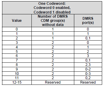
- This table is associated with 38.211-Table 7.4.1.1.2-5 and 38.211-Table 7.4.1.1.2-1.
- Value (index) 0,1,3,4,5,6 = SISO
- Value (index) 2,7,8,11 = 2x2 MIMO
- Value (index) 9 = 3x3 MIMO
- Value (index) 10 = 4x4 MIMO
Interpretation of this table in terms of MIMO are as follows.
- if maxLength is set to 'len1', single-symbol DM-RS can be scheduled for the UE by DCI, and the UE can be configured with a number of additional DM-RS for PDSCH by higher layer parameter dmrs-AdditionalPosition, which can be set to 'pos0', 'pos1', 'pos2' or 'pos3'.
- if maxLength is set to 'len2', both single-symbol DM-RS and double symbol DM-RS can be scheduled for the UE by DCI, and the UE can be configured with a number of additional DM-RS for PDSCH by higher layer parameter dmrs-AdditionalPosition, which can be set to 'pos0' or 'pos1'.
the UE may be configured with the maximum number of front-loaded DM-RS symbols for PDSCH by higher layer parameter maxLength given by DMRS-DownlinkConfig..
- A CDM group consists of DMRS symbols that are mutually orthogonal, meaning they do not interfere with each other.
- Each CDM group can carry either DMRS or PDSCH data.
- "Number of CDM groups without data" represents how many of these groups are reserved only for DMRS and do not carry data.
- A higher number of CDM groups without data means that more resources are allocated to DMRS, improving channel estimation accuracy but reducing spectral efficiency (since fewer resources are available for PDSCH data).
- A lower number of CDM groups without data means fewer DMRS resources are used, improving data throughput but potentially reducing channel estimation quality.
What is CDM group ? :In 5G NR, DMRS symbols are mapped to resource elements (REs) using CDM (Code Division Multiplexing). CDM allows multiple DMRS symbols to be transmitted simultaneously within the same time and frequency resources by using different orthogonal cover codes.
How Does CDM group Affect Transmission?
Following table, extracted from 3GPP TS 38.212
- The table is divided into two main sections:
- One Codeword (Codeword 0 enabled, Codeword 1 disabled)
- Two Codewords (Both Codeword 0 and Codeword 1 enabled)
- For One Codeword, the table provides three key parameters for each value:
- Number of DMRS CDM groups without data: Determines how many CDM groups are allocated solely for DMRS, affecting channel estimation quality and spectral efficiency.
- DMRS port(s): Indicates the assigned antenna port(s) for DMRS transmission.
- Number of front-load symbols: Specifies how many DMRS symbols are placed at the beginning of the transmission for early channel estimation.
- For Two Codewords, the structure is similar but allows for multi-layer MIMO transmission:
- The number of CDM groups without data is set to 2 for all entries.
- The DMRS ports expand to multiple antennas, supporting spatial multiplexing.
- The number of front-load symbols is always 2, ensuring sufficient channel estimation across both codewords.
< 38.212 - Table 7.3.1.2.2-2: Antenna port(s) (1000 + DMRS port), dmrs-Type=1, maxLength=2 >
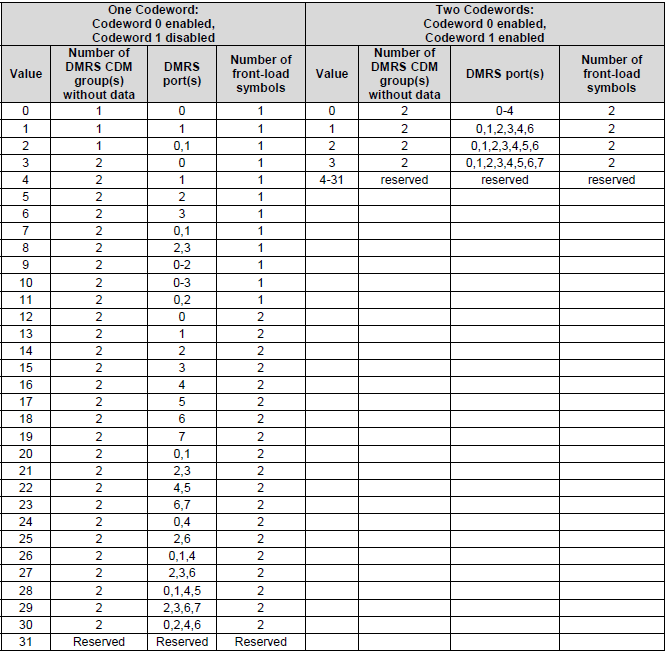
Following table, extracted from 3GPP TS 38.212
- The table is divided into two sections:
- One Codeword (Codeword 0 enabled, Codeword 1 disabled)
- Two Codewords (Both Codeword 0 and Codeword 1 enabled)
- For One Codeword, the table provides:
- Number of DMRS CDM groups without data, which determines the number of CDM groups reserved for DMRS and not used for PDSCH data.
- DMRS port(s), which indicates the assigned DMRS antenna port(s).
- The values range from 0 to 23, with 24-31 being reserved.
- For Two Codewords, the table specifies:
- The number of DMRS CDM groups without data, which is fixed at 3 for valid entries.
- The DMRS port(s), which expands to support multiple antenna ports (spatial multiplexing).
- Values 2-31 are reserved, limiting the available configurations.
This table is critical for configuring PDSCH DMRS in 5G NR, particularly when using Type-2 DMRS, which supports higher flexibility in MIMO transmission and better channel estimation performance in high-mobility scenarios.
< 38.212 - Table 7.3.1.2.2-3: Antenna port(s) (1000 + DMRS port), dmrs-Type=2, maxLength=1 >
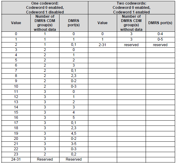
Following table, extracted from 3GPP TS 38.212
- The table is divided into two sections:
- One Codeword (Codeword 0 enabled, Codeword 1 disabled)
- Two Codewords (Both Codeword 0 and Codeword 1 enabled)
- For One Codeword, the parameters defined are:
- Number of DMRS CDM groups without data: The number of CDM groups allocated exclusively for DMRS, which impacts spectral efficiency and channel estimation.
- DMRS port(s): Specifies the antenna ports assigned to DMRS.
- Number of front-load symbols: Defines how many DMRS symbols are positioned at the beginning of the slot to assist in early channel estimation.
- For Two Codewords, the parameters include:
- Number of DMRS CDM groups without data: Set to 2 or 3 based on the value.
- DMRS port(s): Expands to multiple antenna ports to support spatial multiplexing in MIMO scenarios.
- Number of front-load symbols: Fixed at 1 or 2, ensuring robust channel estimation for both codewords.
- Reserved values (e.g., 6-63 for Two Codewords and 58-63 for One Codeword) indicate configurations that are not defined for use.
This table is crucial in configuring PDSCH DMRS in 5G NR, particularly in scenarios requiring high spectral efficiency and robust channel estimation, such as MIMO deployments and high-mobility conditions.
< 38.212 - Table 7.3.1.2.2-4: Antenna port(s) (1000 + DMRS port), dmrs-Type=2, maxLength=2 >
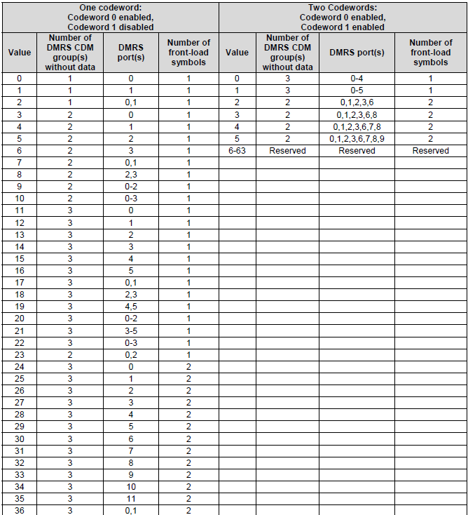
Example : RRC IEs for Table Selection and DCI for Port Selection
The section How MIMO is configured ? says that RRC picks the table and DCI picks the row. This section puts both halves on one configuration, so the path from a setup message to a resource grid runs end to end. I have used dmrs-Type=2 with maxLength=2 for the example. A simpler setting is easier to read, but it hides the two defaults that cause most of the confusion.
Two IEs carry the RRC half. The first is PDSCH-Config, which holds one DMRS configuration per PDSCH mapping type. The second is DMRS-DownlinkConfig, which holds dmrs-Type and maxLength themselves.
Following is based on
PDSCH-Config ::=                        SEQUENCE {
    dataScramblingIdentityPDSCH             INTEGER (0..1023)                                                   OPTIONAL,   -- Need S
    dmrs-DownlinkForPDSCH-MappingTypeA      SetupRelease { DMRS-DownlinkConfig }                                OPTIONAL,   -- Need M
    dmrs-DownlinkForPDSCH-MappingTypeB      SetupRelease { DMRS-DownlinkConfig }                                OPTIONAL,   -- Need M
    -- other fields omitted
    maxNrofCodeWordsScheduledByDCI          ENUMERATED {n1, n2}                                                 OPTIONAL,   -- Need R
    -- other fields omitted
}
Mapping type A and mapping type B carry separate DMRS configurations, and the mapping type of the scheduled PDSCH chooses between them. Only dmrs-Type, dmrs-AdditionalPosition and maxLength may be set differently for the two. The field maxNrofCodeWordsScheduledByDCI sits in the same IE. It decides whether the one codeword half or the two codeword half of the table applies. It also changes the number of MCS, NDI and RV fields in the DCI from one set to two.
Following is based on
DMRS-DownlinkConfig ::=             SEQUENCE {
    dmrs-Type                           ENUMERATED {type2}                                                      OPTIONAL,   -- Need S
    dmrs-AdditionalPosition             ENUMERATED {pos0, pos1, pos3}                                           OPTIONAL,   -- Need S
    maxLength                           ENUMERATED {len2}                                                       OPTIONAL,   -- Need S
    scramblingID0                       INTEGER (0..65535)                                                      OPTIONAL,   -- Need S
    scramblingID1                       INTEGER (0..65535)                                                      OPTIONAL,   -- Need S
    phaseTrackingRS                     SetupRelease { PTRS-DownlinkConfig  }                                   OPTIONAL,   -- Need M
    ...,
    [[
    dmrs-Downlink-r16               ENUMERATED {enabled}                                                        OPTIONAL    -- Need R
    ]],
    [[
    dmrs-TypeEnh-r18                ENUMERATED {enabled}                                                        OPTIONAL    -- Need R
    ]]
}
Two things in this listing are easy to miss, and both matter for table selection. The field dmrs-Type has one value only, type2, and it is optional. When it is absent the UE uses DMRS type 1, so type 1 is never signalled on its own. The field maxLength behaves the same way. Its only value is len2, and an absent field means len1.
That is why a UE on the simplest configuration receives neither field. It still knows it is reading Table 7.3.1.2.2-1, because both defaults apply. A network that wants Table 7.3.1.2.2-4 has to send both fields, as the example does.
< RRC settings used in this example >
|
IE |
Field |
Value |
What it decides |
|
PDSCH-Config |
dmrs-DownlinkForPDSCH-MappingTypeA |
setup |
the DMRS configuration used by a mapping type A PDSCH |
|
DMRS-DownlinkConfig |
dmrs-Type |
type2 |
DMRS type 2, so three CDM groups fit in a resource block |
|
DMRS-DownlinkConfig |
maxLength |
len2 |
the front-load DMRS may use two OFDM symbols |
|
PDSCH-Config |
maxNrofCodeWordsScheduledByDCI |
n1 |
the one codeword half of the table applies |
|
result |
38.212 Table 7.3.1.2.2-4 |
6 bits |
the width of the antenna port field in DCI |
The table is fixed once the setup message is applied. From then on the DCI supplies the row. The field is Antenna port(s) and number of layers in DCI format 1_1, and its width follows from the same two RRC parameters. The UE therefore knows the width of the field before it decodes anything in it.
38.212 clause 7.3.1.2.2 gives that field a width of 4, 5, 6, 7 or 8 bits. The four tables on this page cover the first three widths. Six bits give 64 code points, and values 58 to 63 of Table 7.3.1.2.2-4 are reserved.
One point is worth being exact about. DCI format 1_1 carries a single field for all of this, and the full field list is on the DCI Format 1_1 page. The number of CDM groups without data, the port list and the number of front-load symbols are not separate fields. They are columns of the selected table, and the UE reads them off the row that the code point points at. The table below separates the one transmitted value from the three looked up beside it.
< One DCI field, and the table row it resolves to >
|
Where the value comes from |
Item |
Value |
Meaning |
|
DCI format 1_1, the only field involved |
Antenna port(s) and number of layers, 6 bits |
'101101' |
value 45, so row 45 of Table 7.3.1.2.2-4 applies |
|
38.212 Table 7.3.1.2.2-4, row 45 |
Number of DMRS CDM group(s) without data |
3 |
CDM groups 0, 1 and 2 all carry DMRS and no PDSCH |
|
38.212 Table 7.3.1.2.2-4, row 45 |
DMRS port(s) |
0, 1, 6, 7 |
antenna ports 1000, 1001, 1006 and 1007 |
|
38.212 Table 7.3.1.2.2-4, row 45 |
Number of front-load symbols |
2 |
the DMRS occupies two adjacent OFDM symbols |
|
result |
number of layers |
4 |
four DMRS ports on a single codeword |
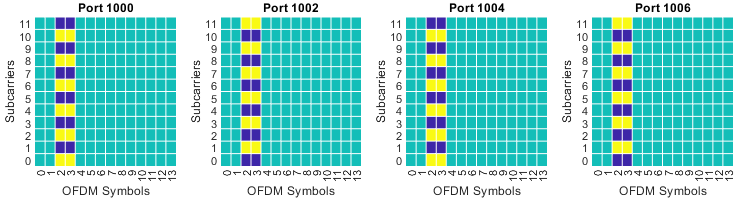
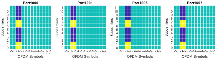
The row is now resolved into a picture. Value 45 reserves all three CDM groups, assigns ports 1000, 1001, 1006 and 1007, and runs the front-load DMRS over two symbols. The value = 45 entry of DMRS Pattern : Table 7.3.1.2.2-4 draws exactly that. Ports 1006 and 1007 share a CDM group with ports 1000 and 1001, and the cover code across the two symbols separates them.
That walk-through covers one row of one table. Seven rows cover the rest. Three of the four tables have a one codeword half and a two codeword half, and the two halves number their values independently, so each of those tables needs two examples.
< One example per table, and per half where a table has two >
|
38.212 Table |
dmrs-Type |
maxLength |
maxNrofCodeWords- |
CDM group(s) without data |
DMRS port(s) |
Front-load symbols |
Antenna port(s) field |
|
7.3.1.2.2-1 |
absent |
absent |
n1 |
2 |
0-3 |
1 |
'1010' = 10 |
|
7.3.1.2.2-2 |
absent |
len2 |
n1 |
2 |
0,1 |
2 |
'10100' = 20 |
|
7.3.1.2.2-2 |
absent |
len2 |
n2 |
2 |
0-7 |
2 |
'00011' = 3 |
|
7.3.1.2.2-3 |
type2 |
absent |
n1 |
3 |
3-5 |
1 |
'10101' = 21 |
|
7.3.1.2.2-3 |
type2 |
absent |
n2 |
3 |
0-5 |
1 |
'00001' = 1 |
|
7.3.1.2.2-4 |
type2 |
len2 |
n1 |
3 |
0,1,6,7 |
2 |
'101101' = 45 |
|
7.3.1.2.2-4 |
type2 |
len2 |
n2 |
2 |
0,1,2,3,6,7,8,9 |
2 |
'000101' = 5 |
The first four columns are the RRC settings. The next three are the contents of the selected row. The highlighted last column is the only value carried in DCI, and it is what selects that row.
Tables 7.3.1.2.2-1 and 7.3.1.2.2-3 have no front-load symbol column, because maxLength is absent for both and the value is therefore always 1. The column above states that fixed value, so the seven rows can be read side by side.
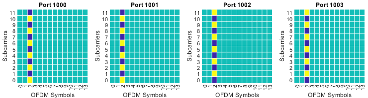
Table 7.3.1.2.2-1 has a one codeword half only. Four ports is its maximum, and a second codeword is used only above four layers, so a two codeword half would have nothing to hold. Value 10 is the largest configuration it offers. It reserves both CDM groups and assigns ports 1000 to 1003, which the reading of this table earlier on the page calls 4x4 MIMO. The value = 10 entry of DMRS Pattern : Table 7.3.1.2.2-1 draws those four ports on the even and the odd comb of a single symbol.
Table 7.3.1.2.2-2 adds the second front-load symbol, and a two codeword half comes with it. Value 20 in the one codeword half is a small configuration. It reserves two CDM groups, assigns ports 1000 and 1001, and spreads the DMRS over two symbols, as the value = 20 entry of DMRS Pattern : Table 7.3.1.2.2-2 shows. Value 3 in the two codeword half is the largest the table reaches. It assigns ports 1000 to 1007, which is eight layers divided between two codewords.
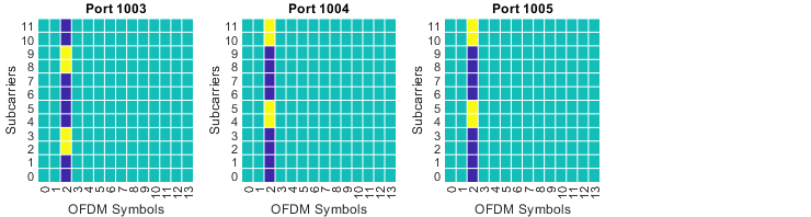
Table 7.3.1.2.2-3 returns to a single front-load symbol and changes the DMRS type to 2. Value 21 in the one codeword half reserves all three CDM groups and assigns ports 1003 to 1005, and the value = 21 entry of DMRS Pattern : Table 7.3.1.2.2-3 draws it. Value 1 in the two codeword half assigns ports 1000 to 1005, which is six layers. That half ends at value 1, so type 2 with one symbol offers two two codeword configurations and no more.
Table 7.3.1.2.2-4 is the only one of the four that reaches eight layers with DMRS type 2. Its one codeword example is value 45, decoded above. Value 5 in the two codeword half assigns ports 1000, 1001, 1002, 1003, 1006, 1007, 1008 and 1009. Two CDM groups are enough for those eight ports. The second front-load symbol supplies the separation that a third CDM group would otherwise have to provide.
One caution applies to every picture on this page. The four galleries draw the one codeword column, so a value in a gallery is the one codeword reading of that code point. The three two codeword rows in the table above have no matching picture. A code point means different things in the two halves, and maxNrofCodeWordsScheduledByDCI is what tells the UE which half to read.
Two later additions sit beside the four tables on this page, and each one redirects the UE to a different table. The first is dmrs-TypeEnh-r18, the last field of DMRS-DownlinkConfig. When it is configured the UE reads Tables 7.3.1.2.2-7 to 7.3.1.2.2-10 instead. The second applies when two TCI states are indicated for the PDSCH. In that case the UE reads the A variant of its table, from Table 7.3.1.2.2-1A to Table 7.3.1.2.2-4A.
The four tables shown on this page are therefore one case out of four. They apply when dmrs-TypeEnh is not configured and a single TCI state is indicated. 38.212 v19.4.0 writes the first half of that condition into the table titles themselves.
RRC selects the table and DCI selects the row : dmrs-Type and maxLength are semi-static, and they also fix the width of the antenna port field at 4, 5 or 6 bits. The field itself changes at every scheduling instant.The two selecting fields are absent in the default case : dmrs-Type absent means type 1, and maxLength absent means len1, so Table 7.3.1.2.2-1 is reached by sending nothing.maxNrofCodeWordsScheduledByDCI chooses the half of the table : the value n1 uses the one codeword columns. The value n2 uses the two codeword columns, and it adds a second set of MCS, NDI and RV fields.One row carries three separate quantities : the number of CDM groups without data, the DMRS port list, and the number of front-load symbols all arrive in the same code point.The same code point means two different things : value 3 selects the single port 1000 in the one codeword half of Table 7.3.1.2.2-2. The same value 3 selects ports 1000 to 1007 in the two codeword half.Table 7.3.1.2.2-1 has no two codeword half : its four ports cannot carry more than four layers, and a second codeword is used only above four.
DMRS Pattern : Table 7.3.1.2.2-1
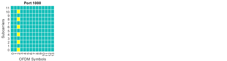
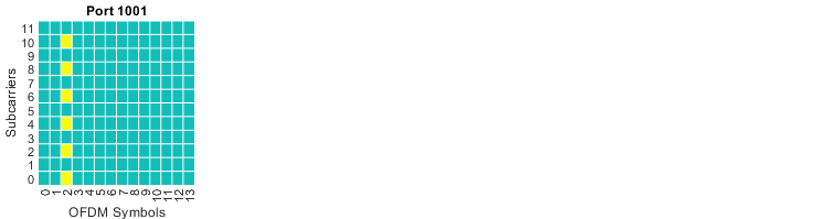
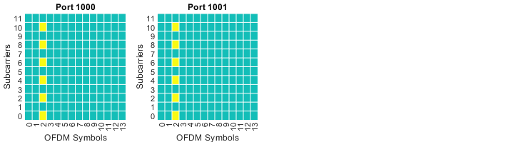
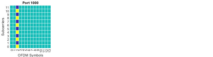
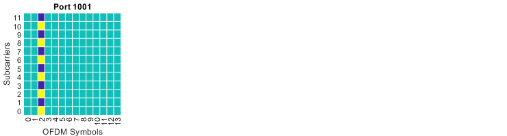
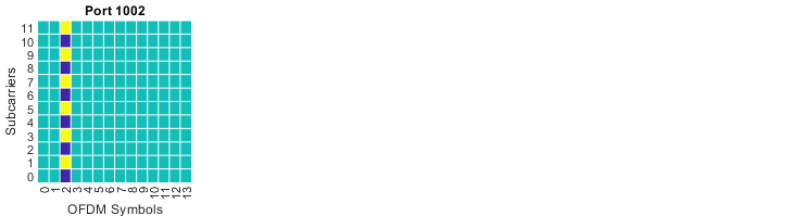
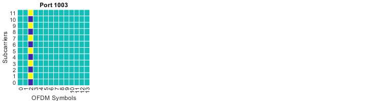
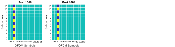
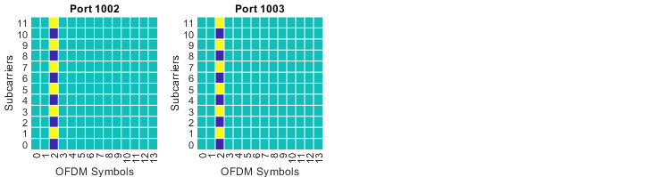
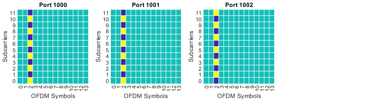
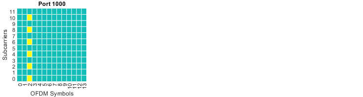
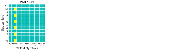
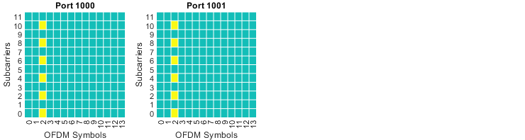
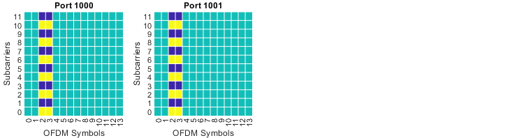
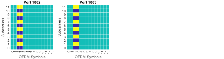
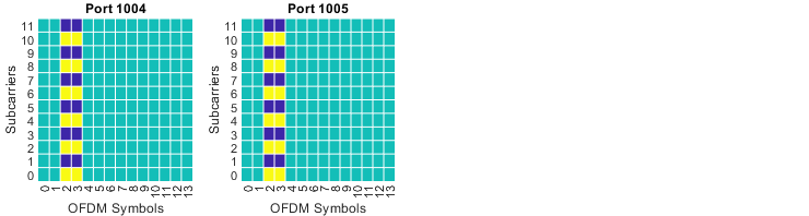
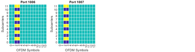
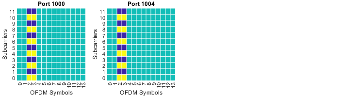
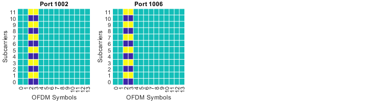
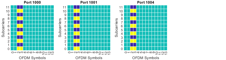
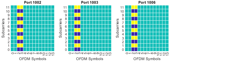
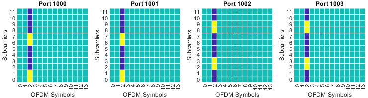
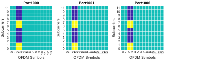
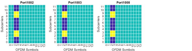
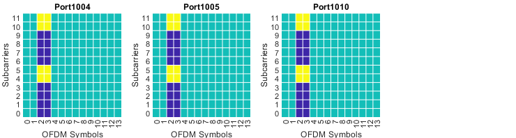
Table 7.3.1.2.2-1 tells you which DMRS ports are used. It does not tell you where those ports sit in the resource grid. That is what this section adds. Each picture below draws one row of the table as a slot, so the value carried in DCI becomes a pattern you can look at.
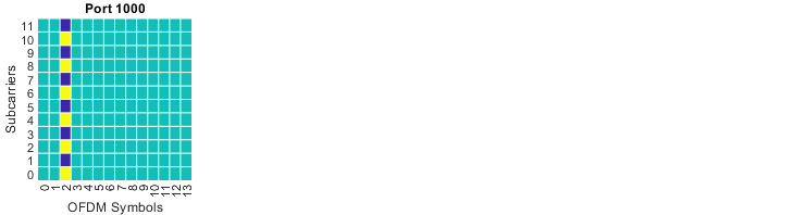
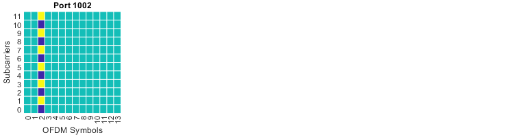
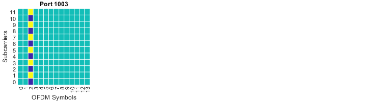
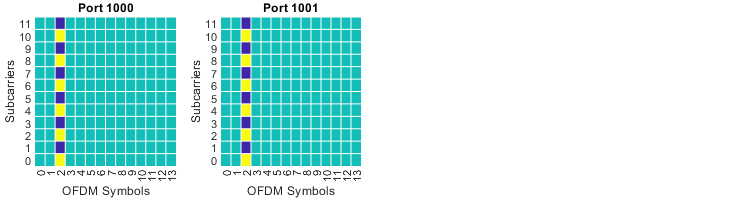
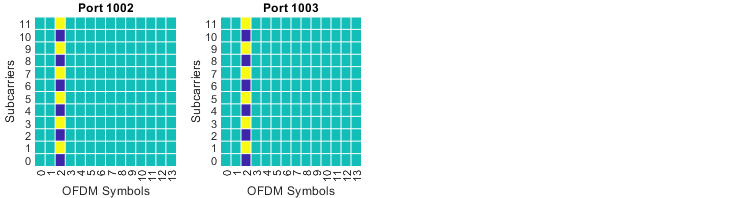
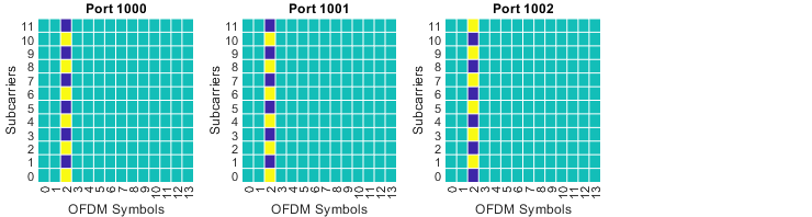
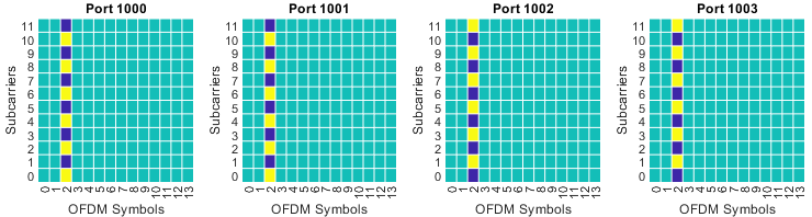
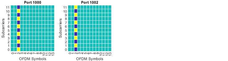
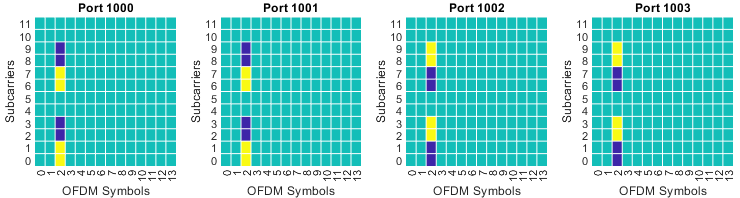
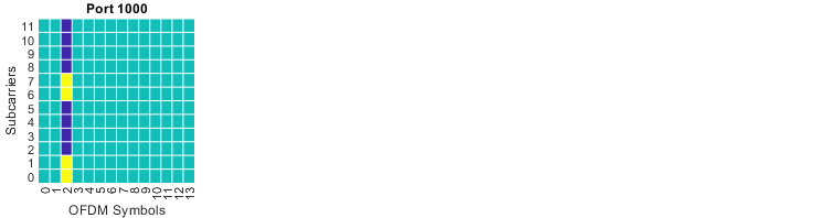
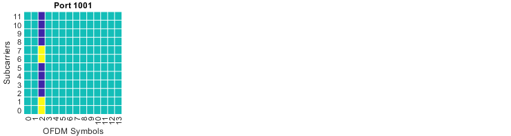
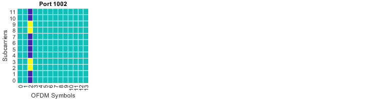
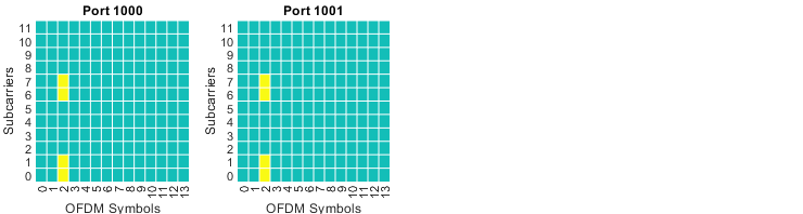
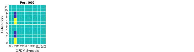
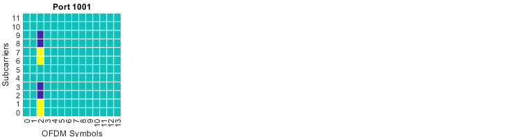
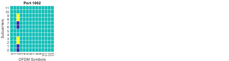
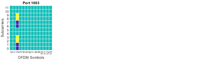
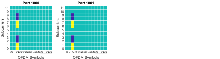
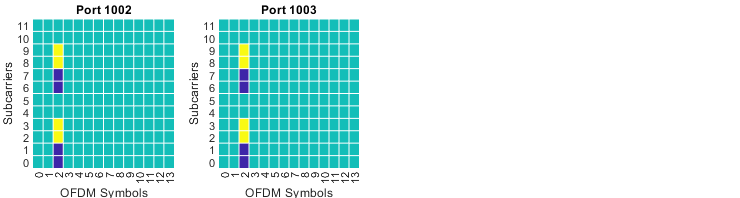
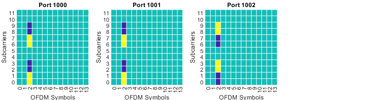
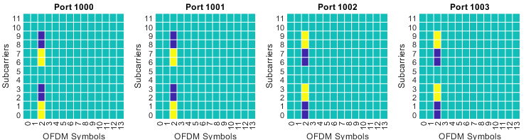
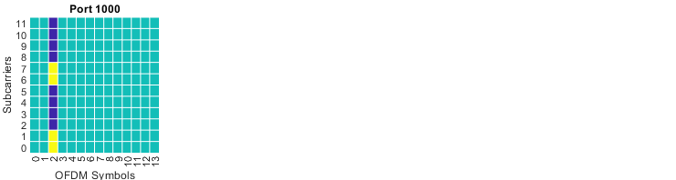
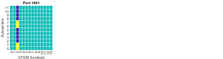
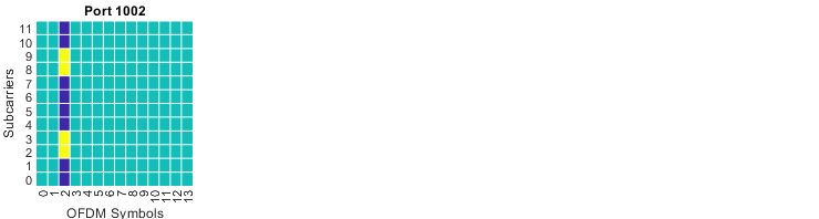
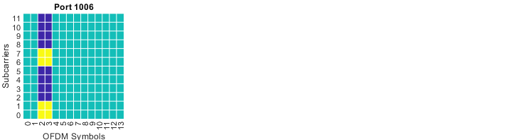
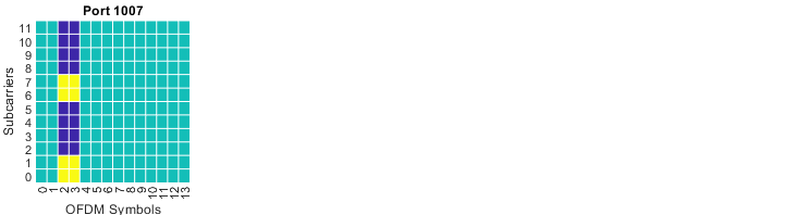
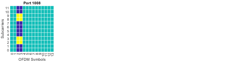
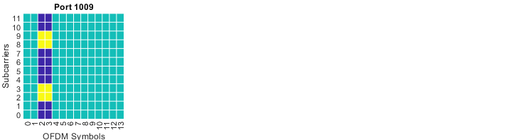
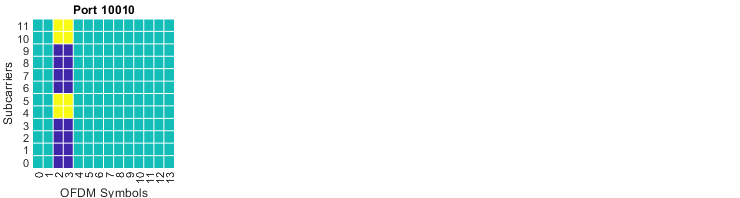
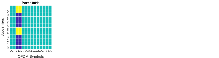
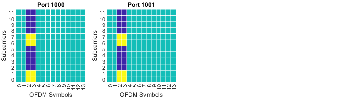
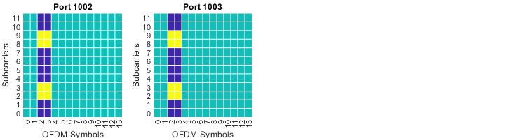
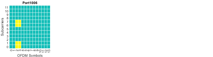
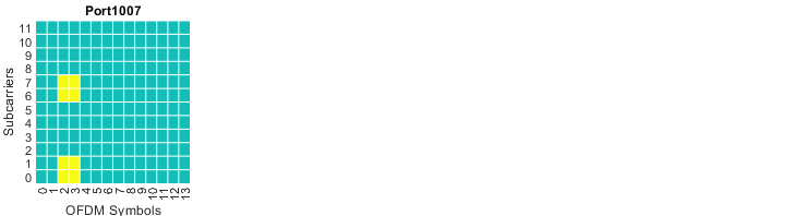
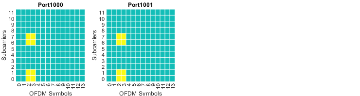
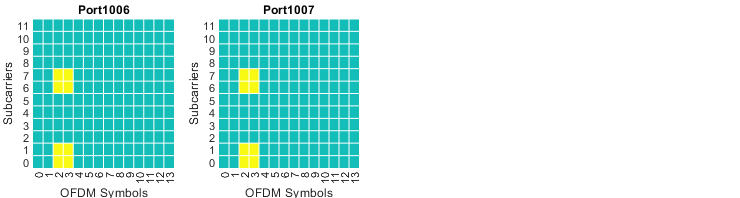
Every picture uses the same layout. The horizontal axis is the fourteen OFDM symbols of a slot. The vertical axis is the twelve subcarriers of one resource block. One grid is drawn per DMRS port, and the port number is written above it. A yellow resource element carries the DMRS of that port. A dark blue resource element belongs to another CDM group, and it carries no data. A green resource element is left for PDSCH.
This is where the column "Number of DMRS CDM group(s) without data" becomes visible. Value 2 and value 7 both assign ports 0 and 1. Value 2 reserves one CDM group, so no resource element is drawn dark blue. Value 7 reserves two CDM groups, so the odd subcarriers of the DMRS symbol turn dark blue. The UE never uses those positions, and PDSCH cannot use them either.
|
value = 0; |
|
|
|
value = 1; |
|
|
|
value = 2; |
|
|
|
value = 3; |
|
|
|
value = 4; |
|
|
|
value = 5; |
|
|
|
value = 6; |
|
|
|
value = 7; |
|
|
|
value = 8; |
|
|
|
value = 9; |
|
|
|
value = 10; |
|
|
|
value = 11; |
|
|
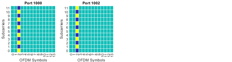
The DCI value selects a pattern, not only a port list : each row of Table 7.3.1.2.2-1 produces one DMRS layout. The receiver has to assume that layout before it can demodulate.dmrs-Type=1 divides the subcarriers into two combs : CDM group 0 takes the even subcarriers and CDM group 1 takes the odd ones. One symbol therefore holds at most two groups.maxLength=1 keeps every pattern inside a single symbol : that is the reason this table stops at four ports, from 1000 to 1003.A reserved CDM group costs PDSCH resource elements : the dark blue positions carry no DMRS for this UE and no data. They protect the DMRS of another UE.Values 12 to 15 have no picture : they are reserved in Table 7.3.1.2.2-1.
DMRS Pattern : Table 7.3.1.2.2-2
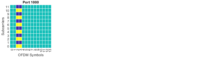
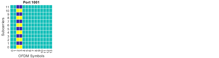
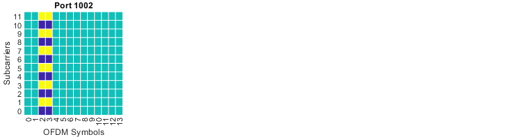
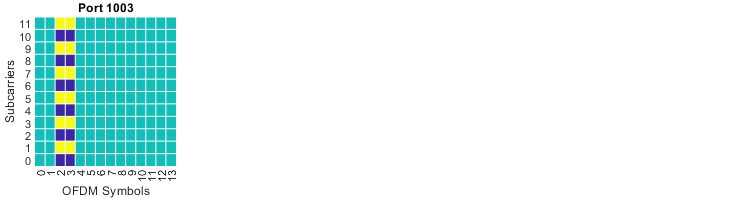
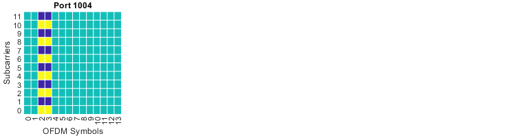
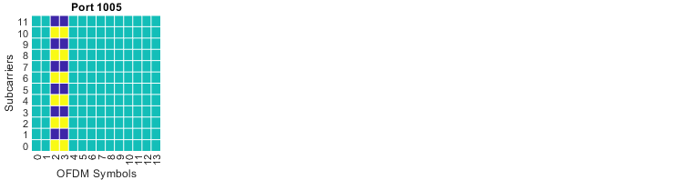
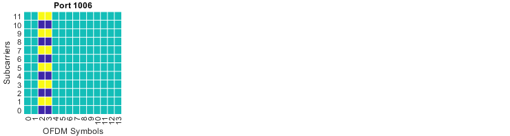
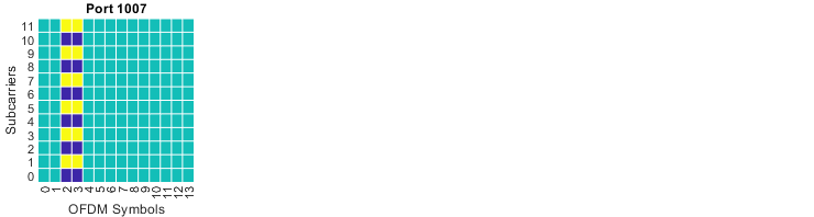
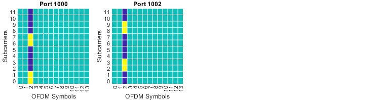
This section covers the same DMRS type as the previous one, with one change. The parameter maxLength is 2, so the DMRS may occupy two adjacent OFDM symbols instead of one. That single change doubles the number of ports the table can address. The pictures make the second symbol easy to spot.
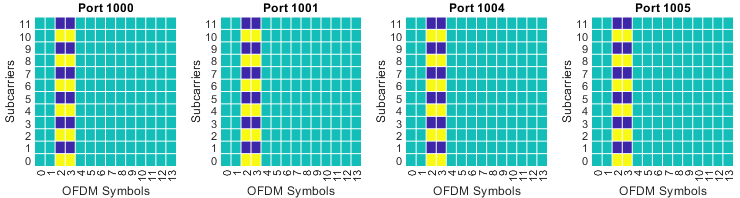
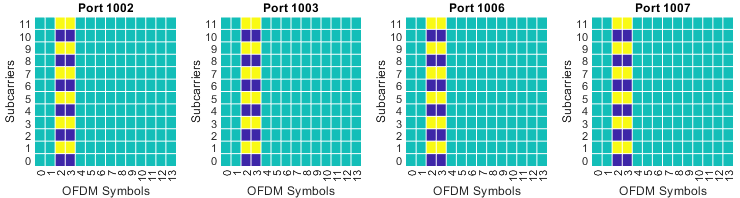
The grids are read exactly as in the previous section. Values 0 to 11 use one front-load symbol, and their patterns keep the shape of Table 7.3.1.2.2-1. From value 12 onwards the number of front-load symbols is 2. In those pictures the marked resource elements run across two neighbouring OFDM symbols.
The second symbol is not a repetition of the first. Ports that share a CDM group are separated by an orthogonal cover code applied across the two symbols. That is how this table reaches ports 0 to 7 while still using only two combs. The cost is one more OFDM symbol taken from PDSCH in every allocation.
|
value = 0; |
|
|
|
value = 1; |
|
|
|
value = 2; |
|
|
|
value = 3; |
|
|
|
value = 4; |
|
|
|
value = 5; |
|
|
|
value = 6; |
|
|
|
value = 7; |
|
|
|
value = 8; |
|
|
|
value = 9; |
|
|
|
value = 10; |
|
|
|
value = 11; |
|
|
|
value = 12; |
|
|
|
value = 13; |
|
|
|
value = 14; |
|
|
|
value = 15; |
|
|
|
value = 16; |
|
|
|
value = 17; |
|
|
|
value = 18; |
|
|
|
value = 19; |
|
|
|
value = 20; |
|
|
|
value = 21; |
|
|
|
value = 22; |
|
|
|
value = 23; |
|
|
|
value = 24; |
|
|
|
value = 25; |
|
|
|
value = 26; |
|
|
|
value = 27; |
|
|
|
value = 28; |
|
|
|
value = 29; |
|
|
|
value = 30; |
|
|
Two front-load symbols double the port count : ports 1000 to 1007 are addressable here, against 1000 to 1003 in Table 7.3.1.2.2-1.The extra ports are separated in time, not in frequency : the comb structure of dmrs-Type=1 is unchanged. The second symbol carries the time domain cover code.The value sets the DMRS duration as well as the ports : values 0 to 11 use one front-load symbol. Values 12 to 30 use two.Two codewords are allowed for four values only : values 0 to 3 of the two codeword column carry five layers or more. Values 4 to 31 are reserved.Value 31 has no picture : it is reserved in Table 7.3.1.2.2-2.
DMRS Pattern : Table 7.3.1.2.2-3
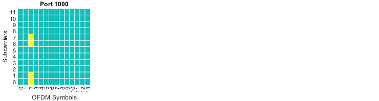
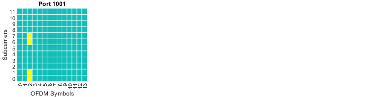
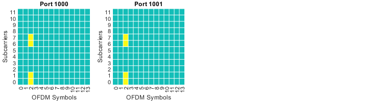
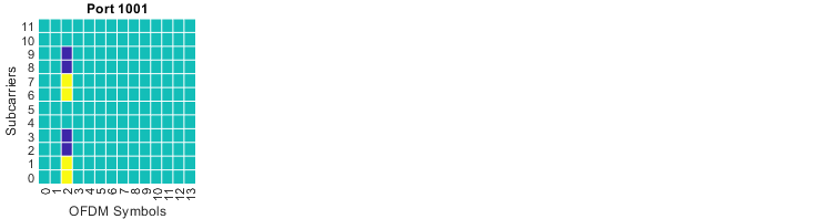
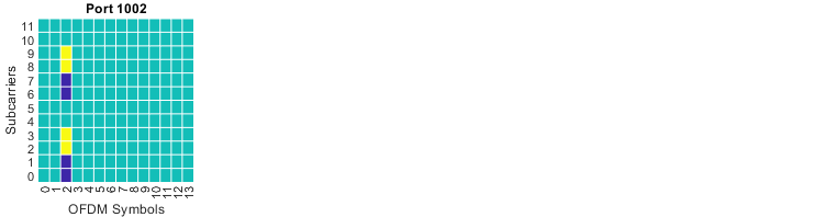
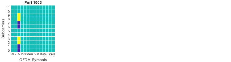
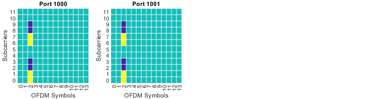
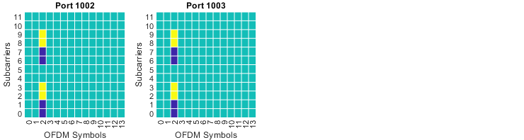
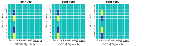
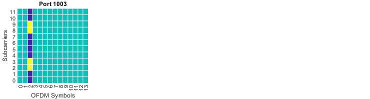
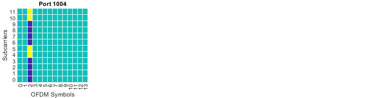
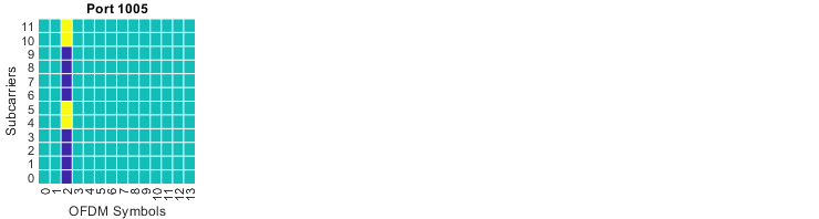
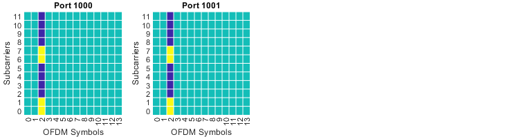
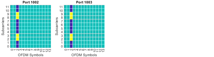
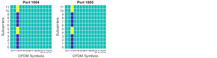
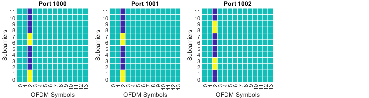
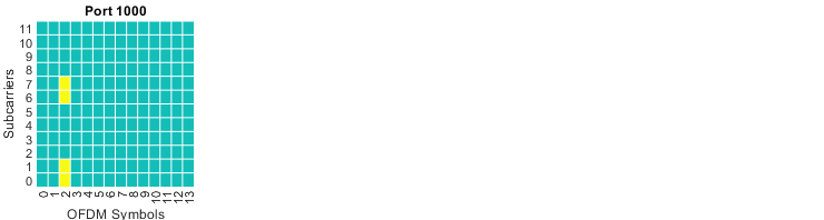
dmrs-Type changes from 1 to 2 in this section, and the frequency pattern changes with it. Type 2 does not use a comb. Each CDM group takes two adjacent subcarriers, and the pattern repeats every six subcarriers. Three CDM groups therefore fit in one resource block, where dmrs-Type=1 fits two.
The grids follow the same reading rules. What differs is where the yellow resource elements sit. A Type 2 port occupies two neighbouring subcarriers, leaves four, then occupies two again. Because a third CDM group fits alongside the other two, the column "Number of DMRS CDM group(s) without data" now reaches 3.
Value 21 is the clearest example in this section. It reserves all three CDM groups and assigns ports 3, 4 and 5. Ports 1004 and 1005 share one CDM group, and the two other groups appear dark blue in every grid. No resource element of that DMRS symbol is left for PDSCH.
|
value = 0; |
|
|
|
value = 1; |
|
|
|
value = 2; |
|
|
|
value = 3; |
|
|

|
value = 4; |
|
|
|
value = 5; |
|
|
|
value = 6; |
|
|
|
value = 7; |
|
|
|
value = 8; |
|
|
|
value = 9; |
|
|
|
value = 10; |
|
|
|
value = 11; |
|
|
|
value = 12; |
|
|
|
value = 13; |
|
|
|
value = 14; |
|
|
|
value = 15; |
|
|
|
value = 16; |
|
|
|
value = 17; |
|
|
|
value = 18; |
|
|
|
value = 19; |
|
|
|
value = 20; |
|
|
|
value = 21; |
|
|
|
value = 22; |
|
|
|
value = 23; |
|
|
Type 2 trades comb spacing for adjacency : a CDM group takes two adjacent subcarriers out of every six, rather than every second subcarrier.Three CDM groups fit in one resource block : that is one more than dmrs-Type=1 allows, so six ports are reachable with a single symbol.Type 2 spends fewer resource elements per port : a CDM group covers four resource elements per resource block, against six for dmrs-Type=1. Channel estimation therefore has fewer samples in frequency.Reserving all three groups empties the DMRS symbol : no PDSCH resource element survives in that symbol. That is the highest overhead a single symbol configuration can reach.Values 24 to 31 have no picture : they are reserved in Table 7.3.1.2.2-3.
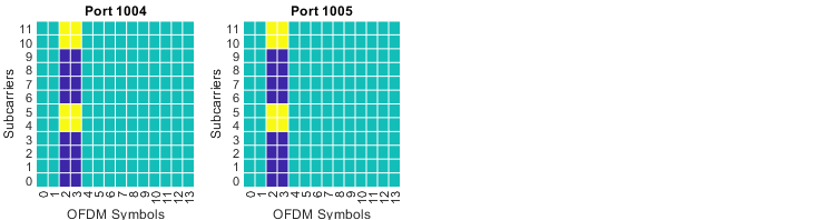
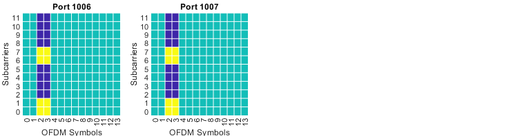
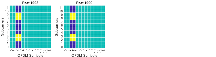
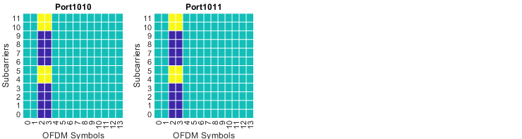
DMRS Pattern : Table 7.3.1.2.2-4
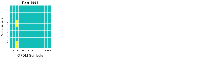
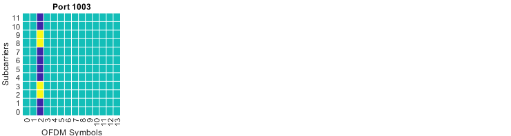
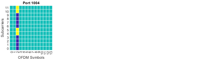
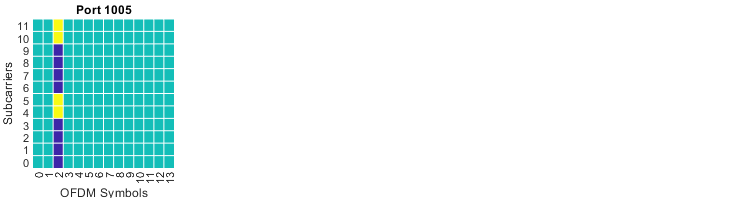
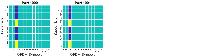
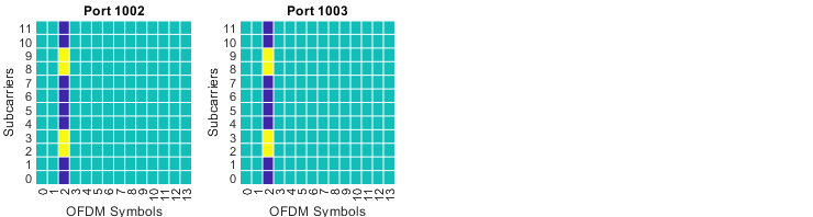
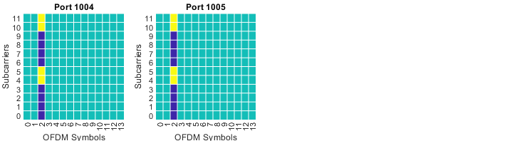
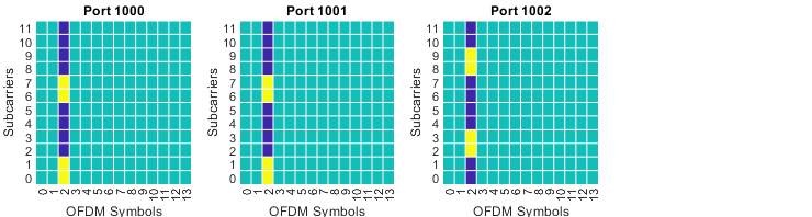
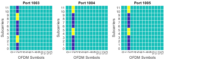
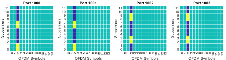
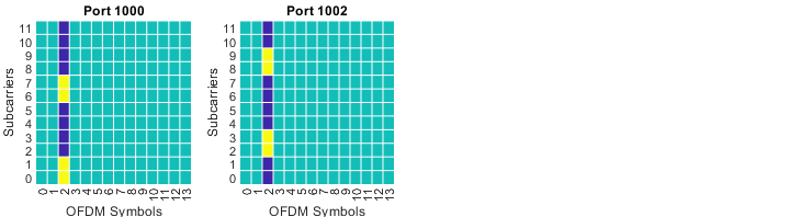
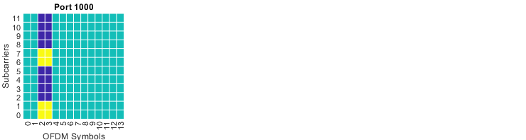
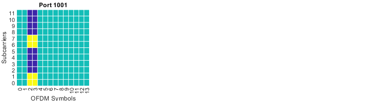
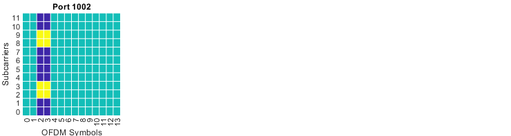
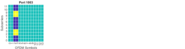
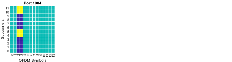
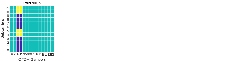
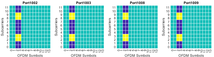
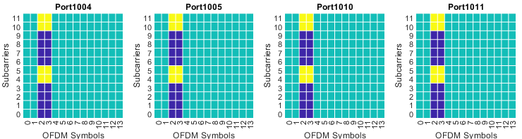
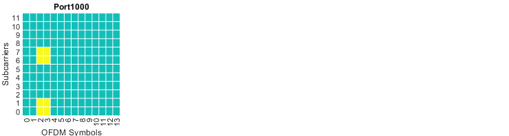
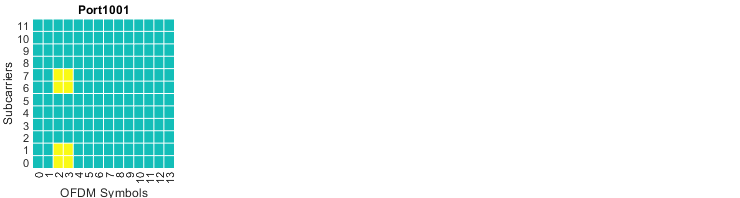
This is the largest of the four tables, and it combines both extensions already described. The parameter dmrs-Type is 2, so three CDM groups fit in a resource block. The parameter maxLength is 2, so each group may run over two OFDM symbols. Together they raise the port count to twelve, and the DCI field to six bits.
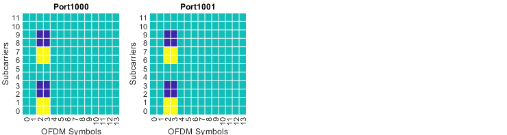
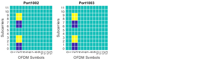
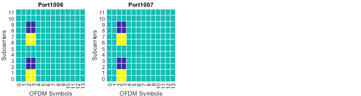
The reading rules do not change. Yellow marks the DMRS of the port named above the grid. Dark blue marks a reserved CDM group. Green is left for PDSCH. Once the number of front-load symbols becomes 2, the marked resource elements cover two adjacent symbols.
Value 45 shows the result of combining them. Three CDM groups are reserved, and the assigned ports are 0, 1, 6 and 7. Ports 1006 and 1007 sit in the same CDM group as ports 1000 and 1001. The four are separated by the cover code across the two symbols, rather than by their position in frequency.
|
value = 0; |
|
|
|
value = 1; |
|
|
|
value = 2; |
|
|
|
value = 3; |
|
|
|
value = 4; |
|
|
|
value = 5; |
|
|
|
value = 6; |
|
|
|
value = 7; |
|
|
|
value = 8; |
|
|
|
value = 9; |
|
|
|
value = 10; |
|
|
|
value = 11; |
|
|
|
value = 12; |
|
|
|
value = 13; |
|
|
|
value = 14; |
|
|
|
value = 15; |
|
|
|
value = 16; |
|
|
|
value = 17; |
|
|
|
value = 18; |
|
|
|
value = 19; |
|
|
|
value = 20; |
|
|
|
value = 21; |
|
|
|
value = 22; |
|
|
|
value = 23; |
|
|
|
value = 24; |
|
|
|
value = 25; |
|
|
|
value = 26; |
|
|
|
value = 27; |
|
|
|
value = 28; |
|
|
|
value = 29; |
|
|
|
value = 30; |
|
|
|
value = 31; |
|
|
|
value = 32; |
|
|
|
value = 33; |
|
|
|
value = 34; |
|
|
|
value = 35; |
|
|
|
value = 36; |
|
|
|
value = 37; |
|
|
|
value = 38; |
|
|
|
value = 39; |
|
|
|
value = 40; |
|
|
|
value = 41; |
|
|
|
value = 42; |
|
|
|
value = 43; |
|
|
|
value = 44; |
|
|
|
value = 45; |
|
|
|
value = 46; |
|
|
|
value = 47; |
|
|
|
value = 48; |
|
|
|
value = 49; |
|
|
|
value = 50; |
|
|
|
value = 51; |
|
|
|
value = 52; |
|
|
|
value = 53; |
|
|
|
value = 54; |
|
|
|
value = 55; |
|
|
|
value = 56; |
|
|
|
value = 57; |
|
|
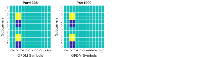
Twelve ports need both extensions at once : three CDM groups give six ports, and the second front-load symbol doubles that to twelve.The upper six ports are code separated : ports 1006 to 1011 reuse the CDM groups of ports 1000 to 1005. They are separated by the time domain cover code.This table costs six bits in DCI : the antenna port field grows from four bits for dmrs-Type=1 with maxLength=1 to six bits here.Overhead reaches its maximum : two symbols with three reserved CDM groups remove two full OFDM symbols of PDSCH from the allocation.Values 58 to 63 have no picture : they are reserved in Table 7.3.1.2.2-4.
Reference
[1] 38.331 v19.3.0 : NR - Radio Resource Control (RRC) protocol specification
[2] 38.212 v19.4.0 : NR - Multiplexing and channel coding