|
Transmission Mode
For the basic understanding on Transmission Mode, please refer to my previous post on Transmission Mode (for Release 8). I would highlight the new TM introduced in Release 10.
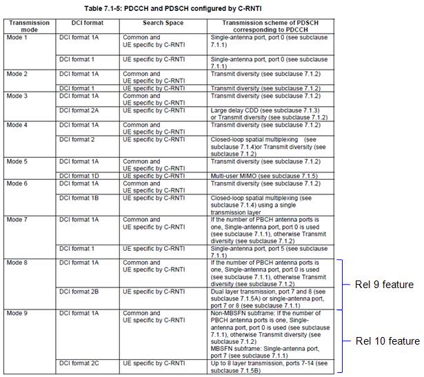
Downlink Transmission Mode
You would see new TMs every time you get additional antenna ports being used and they bring some new idea of using those antenna ports. But as far as I see from the several carrier network configuration as of now (Aug 2013), I only see TM3 being used in the field. (Please let me know if you see other TMs being used in the field).
You can find good introductions on TM9 in the following link :
Transmission Mode and Reference Signal (Antenna Ports)
One of the confusing but important thing about transmission mode is to understand the relationship between each transmissiom mode and reference signal (antenna ports). For this, refer to Reference Signal (Antenna Port Number) vs Transmission Mode in Reference Signal (Downlink) page.
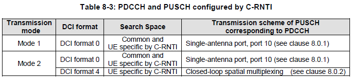
Uplink Transmission Mode
Transmission Mode 9
For Beam Forming aspect of TM9, refer to Beam Forming in LTE section.
|
Format 2C (Release 10) - C-RNTI, SPS C-RNTI - Normal
|
|
Field Name
|
Length (Bits)
|
Comment
|
|
Resource allocation header
|
1 |
RA Type 0 or RA Type 1
|
|
Resource block assignment for RA Type 0
|
6 (1.4 Mhz)
8 (3 Mhz)
13 (5 Mhz)
17 (10 Mhz)
19 (15 Mhz)
25 (20 Mhz)
|
Applicable only when Resource allocation header = 0 (RA Type 0)
Refer to RA Type page
|
| Subset |
N/A (1.4 Mhz)
1 (3 Mhz)
1 (5 Mhz)
2 (10 Mhz)
2 (15 Mhz)
2 (20 Mhz)
|
Applicable only when Resource allocation header = 1 (RA Type 1)
Refer to RA Type page
|
| Shift |
N/A (1.4 Mhz)
1 (3 Mhz)
1 (5 Mhz)
1 (10 Mhz)
1 (15 Mhz)
1 (20 Mhz)
|
Applicable only when Resource allocation header = 1 (RA Type 1)
Refer to RA Type page
|
|
Resource block assignment for RA Type 1
|
N/A (1.4 Mhz)
6 (3 Mhz)
13 (5 Mhz)
14 (10 Mhz)
16 (15 Mhz)
22 (20 Mhz)
|
Applicable only when Resource allocation header = 1 (RA Type 1)
Refer to RA Type page
|
|
TPC for PUCCH
|
2 |
See Power Control section |
|
Downlink Assignment Index
|
2 |
Only Applicable to TDD uplink �downlink configuration 1-6.
|
|
HARQ Process
|
3 (FDD)
4 (TDD)
|
|
| Ports-SCID-Number of Layers |
3 (FDD) |
|
|
MCS for Transport Block 1
|
5 |
|
|
NDI for Transport Block 1
|
1 |
|
|
RV for Transport Block 1
|
2 |
|
|
MCS for Transport Block 2
|
5 |
|
|
NDI for Transport Block 2
|
1 |
|
|
RV for Transport Block 2
|
2 |
|
|
Format 2C (Release 10) - C-RNTI, SPS C-RNTI - CFI
|
|
Field Name
|
Length (Bits)
|
Comment
|
|
Carrier Indicator
|
3 |
|
|
Resource allocation header
|
1 |
RA Type 0 or RA Type 1
|
|
Resource block assignment for RA Type 0
|
6 (1.4 Mhz)
8 (3 Mhz)
13 (5 Mhz)
17 (10 Mhz)
19 (15 Mhz)
25 (20 Mhz)
|
Applicable only when Resource allocation header = 0 (RA Type 0)
Refer to RA Type page
|
| Subset |
N/A (1.4 Mhz)
1 (3 Mhz)
1 (5 Mhz)
2 (10 Mhz)
2 (15 Mhz)
2 (20 Mhz)
|
Applicable only when Resource allocation header = 1 (RA Type 1)
Refer to RA Type page
|
| Shift |
N/A (1.4 Mhz)
1 (3 Mhz)
1 (5 Mhz)
1 (10 Mhz)
1 (15 Mhz)
1 (20 Mhz)
|
Applicable only when Resource allocation header = 1 (RA Type 1)
Refer to RA Type page
|
|
Resource block assignment for RA Type 1
|
N/A (1.4 Mhz)
6 (3 Mhz)
13 (5 Mhz)
14 (10 Mhz)
16 (15 Mhz)
22 (20 Mhz)
|
Applicable only when Resource allocation header = 1 (RA Type 1)
Refer to RA Type page
|
|
TPC for PUCCH
|
2 |
See Power Control section |
|
Downlink Assignment Index
|
2 |
Only Applicable to TDD uplink �downlink configuration 1-6.
|
|
HARQ Process
|
3 (FDD)
4 (TDD)
|
|
| Ports-SCID-Number of Layers |
3 (FDD) |
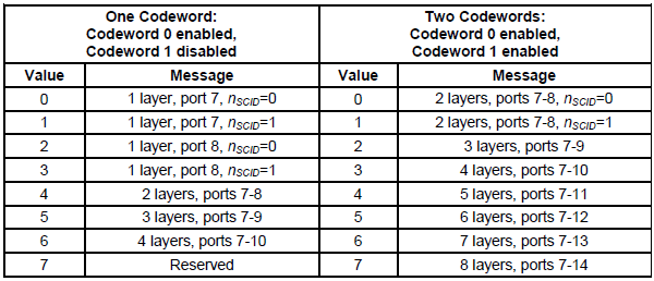
See 36.212 Table 5.3.3.1.5C-1
|
|
MCS for Transport Block 1
|
5 |
|
|
NDI for Transport Block 1
|
1 |
|
|
RV for Transport Block 1
|
2 |
|
|
MCS for Transport Block 2
|
5 |
|
|
NDI for Transport Block 2
|
1 |
|
|
RV for Transport Block 2
|
2 |
|
< 36.212 Table 5.3.3.1.5C-1: Antenna port(s), scrambling identity and number of layers indication >
|
Example 1 : FDD - Format 2C (Release 10) - C-RNTI, SPS C-RNTI - Normal = 7E0000102F2F00
|
|
Field Name
|
Value (Binary)
|
Meaning
|
|
Resource allocation header
|
0 |
RA Type 0
|
|
Resource block assignment for RA Type 0
|
1111110000000000000000000
|
24 RBs
|
|
TPC for PUCCH
|
01 |
|
|
HARQ Process
|
000
|
|
| Ports-SCID-Number of Layers |
000 |
|
|
MCS for Transport Block 1
|
10111(23 Dec) |
|
|
NDI for Transport Block 1
|
1 |
|
|
RV for Transport Block 1
|
00 |
|
|
MCS for Transport Block 2
|
10111(23 Dec) |
|
|
NDI for Transport Block 2
|
1 |
|
|
RV for Transport Block 2
|
00 |
|
|
Example 2 : FDD - Format 2C (Release 10) - C-RNTI, SPS C-RNTI - Normal = 7E0000102F0140
|
|
Field Name
|
Value (Binary)
|
Meaning
|
|
Resource allocation header
|
0 |
RA Type 0
|
|
Resource block assignment for RA Type 0
|
1111110000000000000000000
|
24 RBs
|
|
TPC for PUCCH
|
01 |
|
|
HARQ Process
|
000
|
|
| Ports-SCID-Number of Layers |
000 |
|
|
MCS for Transport Block 1
|
10111(23 Dec) |
|
|
NDI for Transport Block 1
|
1 |
|
|
RV for Transport Block 1
|
00 |
|
|
MCS for Transport Block 2
|
00000(0 Dec) |
|
|
NDI for Transport Block 2
|
1 |
|
|
RV for Transport Block 2
|
01 |
|
|