When we study a new technology.. one of way to efficiently learn/understand about it would be to assume that you are the designer/developer of the technology and ask yourself "Now I have this and this problem in such and such situation. How can I resolve the issue ?". If you keep asking the same questions to yourself, you would have some form of answer even though it may not be technically in detail and it may not be the solution that is really being used in the field. But don't be discouraged.. there is no absolute solutions for most of those problems.. probably your answer would be better than the one that is really being used.
In LTE, the eNB controls the uplink power of every UE, channel by channel and subframe by subframe. The UE sets the power of PUSCH, PUCCH, SRS and PRACH from two parts. The open loop part comes from its own pathloss estimate, and the closed loop part comes from TPC commands. This page first builds that idea from first principles, and then reads each formula of 36.213 clause 5.
|
Followings are the topics to be covered in this page. As you read through the page, you will notice that none of them is as simple as you might have thought. At first, read through 'Overview' section and get a big picture and then come back to details every time when you have specific issue while you are developing or testing. |
Overview
Every uplink channel in LTE has the same problem. The eNB must receive each UE at about the right power, whatever the distance between them. If the power is too low, the eNB cannot decode the signal. If it is too high, the UE interferes with other UEs and wastes its battery.
Now I will talk about the power control issues in LTE.
Before we go into the LTE specific power control, let's try with our own thought process for this power control issue. In wired communication, the amount of energy (power) being sent from the transmitter reachs the reciever without much degradation. Just think about connecting two PC with a long ethernet cable (e.g, around 10 m) and connecting a device to your PC with a simple RS 232 cables (usually less than 2 m). If you measure the voltage at the two ends of the cables while communicating, you will not see much voltage drops between the source and the destination. (Of course there is a certain amount of voltage drops. but the drop is not so big that it cannot be recognized by the reciever). However, what if the transmitter and reciever is connected wirelessly ?
You can intuitively know that the energy drop will be tremandous. Anybody who tried to measure something wirelessly (e.g, test a mobile phone with antenna, not with cable connection with Network simulator or spectrum analyzer) would have experienced these energy drop every time they do the test.
Then how do solve the problem ? This is the time that you assume you become a designer and have to come up with an idea to solve this issue.How do you handle this situation ?
The simplest way would be to use a very high gain amplifier on transmitter and blast huge powered signal to reciever.This method would be good when the reciever and the transmitter is in a reasonable distance. But what if the distance between reciever and transmitter is too close ? In this case, the strong signal from the transmitter may saturate the reciever.
Then how do you handle this situation ? You may try to tune down the transmitter amplifier power so that the receiver does not get saturated. If the distance between transmitter and reciever does not change and the channel condition (Humidity, precipitation, buildings) does not change, this kind of manual tuning would work. But can we do the same thing with mobile communication where the distance between reciever and transmitter changes very often and channel condition changes as well.
Now you have think up a solution to cope with this kind of varying distance and changing channel condition.
The way the people in this area came out is as follows :
i) Transmit send a signal to reciever
ii) Reciever measure the power of the signal from the transmitter
iii) if the measured power is too low, the reciever send a special command saying "increase the power". And if the measured power is too strong, it would send another command saying "decrease the power".
By this mechanism, the transmitter can change it's output power dynamically. This kind of power control mechanism is often called "Closed Loop Power Control" and the special command being used for power control is called TPC (Transmit Power Control) command. In short, Transmit send something and the reciever send a feedback to the transmitter and the reciever retunes itself by the feedback. This whole process forms a cyclic loop and this kind of control loop is called "Closed Loop" in control system theory.This kind of power control is used in almost all the mobile communication technology (e.g, CDMA, WCDMA, LTE and even in Bluetooth etc). This kind of power control process happens much more frequently than you may think. For example, in WCDMA case it would happen around 1500 times maximum within a second ideally. and in LTE case it can happen maximum 1000 times within a second.
If you are a person who is really interested in the power control mechanism and thought in very details about various communication environment, you may notice that there is a situation where we cannot use this kind of "command based power control" method. The 'command based power control'mechansm is based on a asumption that the transmitter and reciever has already established a call setup so thta they can exchange these command.
What if the transmitter and reciever is not in such a communication state ? For example, you just turned on your mobile phone and the mobile phone (transmitter in this case) has to send some signal to the base station (the reciever in this case).
How strong power the mobile phone has to transmit it's first signal ?This is very important.. if the mobile phone transmit the signal in too low power, the base station would not detect it.. and if it transmit it in too high power, it can interfere with the communication between other mobile phone and the base station. So it has to determine the proper transmit power level which would be strong enough to be properly decoded by the base station and weak enough not to interfere the communication between other mobile phone and the base station.
How do you handle this situation ? What kind of method the UE should use to determin the proper transmission power ?
It would not be easy to think out a solution intuitively...
Overall logic that is commonly used in mobile phone communication system is as follows :
i) Network (Base Station) is tranmitting a certain reference signal with a fixed power value
ii) Network transmit the information (e.g, Power) about the reference signal it is transmitting
iii) Network also transmit the maximum allowable power that UE can transmit.
iv) UE decode the reference signal comming from the base station and measured the power.
v) UE can figure out the path loss between the UE and base station by comparing the result of step iv) and ii).
vi) Also from the information at step ii), UE knows how much power is allowed for it.
vii) From the result at step v) and step vi), UE can figure out how much power it can really transmit.
This kind of process is also called a power control process. But since this power determination process is not based on a feedback loop as in Closed Loop Power Control, it is called "Open Loop Power Control".
Closed loop power control needs a connection : the receiver measures the signal and sends TPC commands back to the transmitter.Open loop power control works without one : the UE estimates the pathloss from a reference signal whose power it knows.LTE uses both : the open loop part sets the starting point, and TPC commands correct it.
Open Loop and Closed Loop Power Control
There are roughly two different way of power control mechanism. One is called Open Loop Power control and the other one is called Closed Loop Power Control.
Don't be confused by the term 'Loop'. When we say 'Open Loop', it does not mean 'Loop' control. It is just one directional control process, there is no feedback as illustrated below. (Actually 'a control path that does not have any feedback input' is the definition of Open Loop in control theory.. but it often cause a lot of confusion to many people).
In Open Loop Control, UE determines its Transmission Power by its own Power Setting Algorithm. This Power Setting Algorithm takes in many inputs, but all of these inputs are from UE internal setting or measurement data by the UE. There is no feedback input from eNB.
< Overall Flow for Open Loop Power Control >
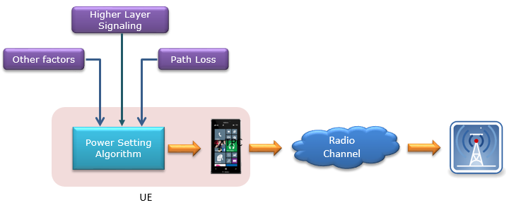
In open loop power control, every input to the power setting algorithm is inside the UE. No input comes back from the eNB.
One of the most common example of Open Loop Power Control is the initial PRACH power. This PRACH power is determined as illustrated below.
< Overall Flow for Open Loop Power Control : PRACH>
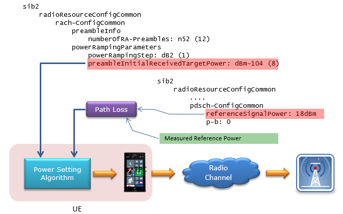
For the first PRACH preamble, the UE takes the target power from SIB2 and adds the pathloss it derives from referenceSignalPower.
The numbers in the picture make a quick example. SIB2 sets preambleInitialReceivedTargetPower to -104 dBm and referenceSignalPower to 18 dBm. Suppose the UE measures an RSRP of -82 dBm. The pathloss is then 18 - (-82) = 100 dB, so the UE sends its first preamble at -104 + 100 = -4 dBm. The PRACH Power Control section below gives the full formula.
Once initial PRACH is detected, the UE power is controlled dynamically by TPC (Transmission Power Control) command (MAC CE or TPC field in DCI 0). It means UE Transmission Power is controled by some feedback input from eNB. In this way, overall power control process form a loop (closed loop). That's why it is called Closed Loop Control.
< Overall Flow for Closed Loop Power Control >
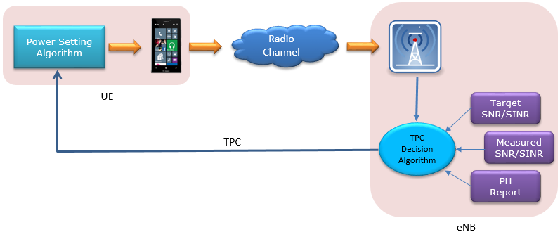
The eNB compares the measured SNR or SINR with its target, takes the PH report into account, and sends TPC commands back to the UE.
The TPC decision algorithm on the eNB side is not specified by 3GPP. Each eNB vendor designs its own. The specification fixes only the other end of the loop: how the UE applies a TPC command to its power. The PUSCH and PUCCH sections below show those rules.
Open loop has no feedback : the UE computes its power only from its own inputs.The first PRACH preamble is the typical open loop case : the target power from SIB2 plus the estimated pathloss.Closed loop adds TPC commands : the eNB decides them, and 36.213 fixes how the UE applies them.
Power Control in LTE
36.213 gives each uplink channel its own power formula. The formulas look different, but they are built from the same parts: a target received power, a pathloss term, a bandwidth term and a closed loop correction. All of them also share one upper limit, PCMAX. This section looks at that common structure first.
For details of LTE specific power control, you have to refer to
"TS 36.213 - 5. Power Control" and if you want to have some hands-on experience of these, I would recommand you to try some test items on 36.521.
For PRACH Power, refer to "TS 36.213 - 6.1 Physical non-synchronized random access procedure".
Power Control in LTE can be summerized by the following equations. The main purpose for this section is to understand the every details of these equations. This is the summary of the Power Setting Algorithm in the block diagram in previous section.
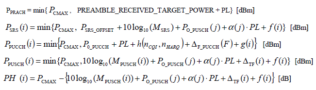
The Release 8 power formulas of 36.213 for PRACH, SRS, PUCCH and PUSCH, and the power headroom.
Since it is not easy to embed the mathematical symbols in this blog, I would express these symbols in text form as shown below.
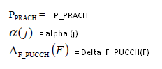
Let's have some overview of formula structure of the list I put above. 4 out of 5 formula has the following structure.
P_Channel(i) = min{P_CMAX, Formula}
P_Channel(i) means "Power of the Channel for each subframe", implying that these channel power is calculated and set for every subframe.
min{P_CMAX, Formula} means "Take the minimum value (smaller value) between P_CMAX, "Formula"".
It means..
i) if the formula give the value smaller than P_CMAX, the P_Channel(i) became the value given by the formula.
ii) if the formula give the value greater than P_CMAX, the P_Channel(i) became P_CMAX value.
Combining these two, it means that P_Channel(i) cannot be greater than P_CMAX.
But there is one power that does not take this format. it is PH(i) which has following format
PH(i) = P_CMAX - Formula.
In this case, what would be the maximum possible value that PH(i) can have ? It is also P_CMAX because the equation says "P_CMAX substracted by Formula". Assuming the "Formula" give you only positive value, the maximum possible value for PH(i) as well become P_CMAX.
Considering all of these, one thing I can know for sure is that in any case any of Uplink power for any specific channel cannot be greater than P_CMAX.
What is P_CMAX ? It is the maximum UE transmitter power specified in 3GPP 36.101. UE manufacturer has to make it sure that UE does not transmit any power greater than this power.
The P_CMAX in various case is derived from various formula and tables, so I would recommend to refer to "6.2.5 Configured transmitted Power" of 36.101. But practically you can take this value as a UE class power defined as in the
following table of 36.101.
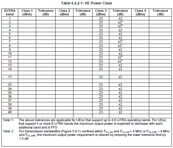
36.101 Table 6.2.2-1 in an early release. Only Power Class 3, 23 dBm, is filled in.
The table above comes from an early release of 36.101. In 36.101 v20.0.0, Table 6.2.2-1 also has Power Class 1 at 31 dBm and Power Class 2 at 26 dBm. These higher classes apply only to a limited set of bands, such as Band 14, Band 40 and Band 42. Power Class 3 at 23 dBm is still the default for most bands.
PCMAX is also not a single fixed number. 36.101 clause 6.2.5 lets the UE set PCMAX,c for each serving cell c within two bounds. The upper bound PCMAX_H,c is the lower of PEMAX,c and the power class, where PEMAX,c is the P-Max value that the cell signals. The lower bound PCMAX_L,c also subtracts the allowed power reductions, such as MPR, A-MPR and P-MPR. So a UE with a wide allocation or a high order modulation may use a PCMAX,c a few dB below its power class.
The subscript c comes from carrier aggregation. Since Release 10, every term in the formulas above carries a serving cell index in 36.213, and the UE runs one set of formulas per serving cell. The last section of this page covers what else changed.
Four formulas share one cap : P_Channel(i) = min{P_CMAX, Formula} for PRACH, SRS, PUCCH and PUSCH.PH is a difference, not a cap : PH = P_CMAX minus the PUSCH formula.PCMAX,c is set per serving cell : between PCMAX_L,c and PCMAX_H,c in 36.101 clause 6.2.5.Power Class 3 is 23 dBm : Power Classes 1 and 2 add 31 dBm and 26 dBm on a few bands.
PUSCH Power Control
PUSCH carries user data, so its power must follow the size of each grant. The formula below does that with five terms. PO_PUSCH and α come from RRC, and PL comes from the UE's own measurement. MPUSCH and ΔTF follow each grant, and f(i) follows the TPC commands.
Refer to 36.213, 5.1 Uplink Power Control if you want to know in very detail.
Now let's look into P_PUSCH(i) first. I will write the equation in my text format for easy typewriting.
P_PUSCH(i) = min{P_CMAX, 10 log(M_PUSCH(i)) + P_O_PUSCH(j) + alpha(j) PL + Delta_TF(i) + f(i)
i : Subframe Number
j : This can be 0, 1 or 2
M_PUSCH(i) : Number of Resource Blocks allocated for the UE
P_O_PUSCH(j) : P_O_NOMINAL_PUSCH(j) + P_O_UE_PUSCH(j),
where P_O_NOMINAL_PUSCH(j) and P_O_UE_PUSCH(j) for j = 0, 1 come from higher layer.
P_O_NOMINAL_PUSCH(j) come from p0-NominalPUSCH in SIB2
P_O_UE_PUSCH(j) come from p0-UE-PUSCH (e.g, SIB2,RRC Connection Setup,
RRC Connection Reconfig)
The index j tells the UE which kind of grant the PUSCH belongs to. The value 0 means a semi-persistent grant, and 1 means a dynamically scheduled grant. The value 2 means the grant in the random access response, which schedules Msg3. For j = 2, PO_UE_PUSCH is 0 and α is 1, and the nominal part comes from the preamble target power. 36.213 v19.4.0 adds two more values: j = 3 for a BL/CE UE on preconfigured uplink resources, and j = 4 for CB-Msg3-EDT.
Following is an example you may see in SIB2 from live network or test equipment.
< SIB2 : uplinkPowerControlCommon > RRC capture. Field values are from a live capture, not from the specification.
sib2
    radioResourceConfigCommon
        ...
        uplinkPowerControlCommon
            p0-NominalPUSCH: -85dBm
            alpha: al08 (5)
            p0-NominalPUCCH: -117dBm
            deltaFList-PUCCH
                deltaF-PUCCH-Format1: deltaF0 (1)
                deltaF-PUCCH-Format1b: deltaF3 (1)
                deltaF-PUCCH-Format2: deltaF0 (1)
                deltaF-PUCCH-Format2a: deltaF0 (1)
                deltaF-PUCCH-Format2b: deltaF0 (1)
Following is an example you may see in RRC Connection Setup message from live network or test equipment.
< RRC Connection Setup : uplinkPowerControlDedicated > RRC capture. Field values are from a live capture, not from the specification.
rrcConnectionSetup-r8
    radioResourceConfigDedicated
        ....
            uplinkPowerControlDedicated
                p0-UE-PUSCH: 0dB
                deltaMCS-Enabled: en0 (0)
                ..1. .... accumulationEnabled: True
                p0-UE-PUCCH: 0dB
                pSRS-Offset: 0
                filterCoefficient: fc4 (4)
This capture shows the dedicated half of the same parameters. The fields p0-UE-PUSCH and p0-UE-PUCCH are both 0 dB, so this UE uses the nominal values of the cell unchanged. The field deltaMCS-Enabled is en0, and accumulationEnabled is True. Both come back further down, in ΔTF and in f(i).
alpha(j) : For j = 0, 1, alpah(j) can be any one of {0, 0.4, 0.5, 0.6, 0.7, 0.8, 0.9, 1}. The specified value come from higher layer (e.g, SIB2).
Following is an example you may see in SIB2 from live network or test equipment.
< SIB2 : alpha > RRC capture. Field values are from a live capture, not from the specification.
sib2
    radioResourceConfigCommon
        ...
        uplinkPowerControlCommon
            p0-NominalPUSCH: -85dBm
            alpha: al08 (5)
            p0-NominalPUCCH: -117dBm
            deltaFList-PUCCH
The value al08 means α = 0.8. This is fractional pathloss compensation: the UE compensates only 0.8 dB of each additional 1 dB of pathloss. So the eNB receives a cell edge UE at a lower power than a cell centre UE. This limits the interference that cell edge UEs cause in neighbour cells.
PL : Downlink Pathloss. This is calculated by referenceSignalPower – higher layer filtered RSRP
"Reference Signal Power" is defined by the following Information Element (SIB2, Refer to 36.331).
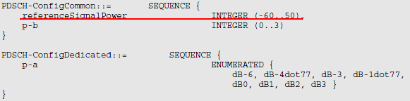
Following is an example you may see in SIB2 in real network or test equipment
< SIB2 : pdsch-ConfigCommon > RRC capture. Field values are from a live capture, not from the specification.
sib2
    radioResourceConfigCommon
        ....
        pdsch-ConfigCommon
            referenceSignalPower: 18dBm
            p-b: 0
The value referenceSignalPower is the EPRE of the cell-specific reference signal in dBm, and RSRP is also a power per resource element. So the UE can subtract one from the other. With the 18 dBm in this capture, a UE that measures an RSRP of -90 dBm estimates PL = 18 - (-90) = 108 dB. PDSCH-ConfigCommon in 36.331 v19.3.0 is the same as the definition above.
"higher layer filtered RSRP" is configured by the combination of following information elements(RRC Connection Setup and RRC Connection Reconfiguration, Refer to 36.331)
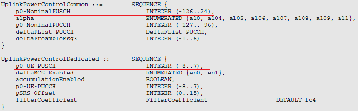
The filter itself is filterCoefficient in UplinkPowerControlDedicated. It sets the layer 3 filter that smooths RSRP before the UE uses it for PL, and its default is fc4. The capture above uses fc4 as well.
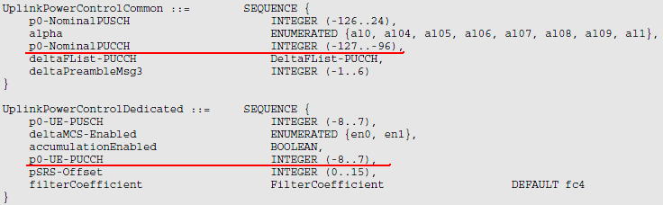
The image above shows the Release 8 definitions. The listing below is the current text. The fields are the same, and only the type of alpha has changed: it is now the separate type Alpha-r12, with the same eight values. Later releases add fields in separate extension IEs, and the last section of this page lists them.
Following is based on
UplinkPowerControlCommon ::=        SEQUENCE {
    p0-NominalPUSCH                     INTEGER (-126..24),
    alpha                               Alpha-r12,
    p0-NominalPUCCH                     INTEGER (-127..-96),
    deltaFList-PUCCH                    DeltaFList-PUCCH,
    deltaPreambleMsg3                   INTEGER (-1..6)
}

UplinkPowerControlDedicated ::=     SEQUENCE {
    p0-UE-PUSCH                         INTEGER (-8..7),
    deltaMCS-Enabled                    ENUMERATED {en0, en1},
    accumulationEnabled                 BOOLEAN,
    p0-UE-PUCCH                         INTEGER (-8..7),
    pSRS-Offset                         INTEGER (0..15),
    filterCoefficient                   FilterCoefficient               DEFAULT fc4
}

Alpha-r12 ::=                       ENUMERATED {al0, al04, al05, al06, al07, al08, al09, al1}
Delta_TF(i) = 10 log((2^(MPR * Ks) - 1) beta_PUSCH_offset) when Ks = 1.25
Delta_TF(i) = 0 when Ks = 0, where Ks comes from Higher Layer
Ks is deltaMCS-Enabled: en0 gives Ks = 0, and en1 gives Ks = 1.25. In the RRC Connection Setup capture above, deltaMCS-Enabled is en0. So for that UE ΔTF is always 0 dB, and PUSCH power does not change with the MCS. With Ks = 1.25, the power grows with the bits per resource element, which the formula above calls MPR and current 36.213 calls BPRE. A higher MCS then gets more power.
f(i) = f(i −1) +delta_PUSCH (i − K_PUSCH ),
where delta_PUSCH is TPC command carried by DCI format 0 or DCI format 3/3a. Following table from 36.213 shows the mapping between TPC value and Power Up/Down.
Followng table defines how you should interpret the TPC value in DCI into the real power changes. As you see here, the same TPC value will converted to different physical power changes depending on whether the power control mode is 'Accumulated mode' or 'Absolute mode'.
< 36.213 - Table 5.1.1.1-2: Mapping of TPC Command Field in DCI format 0/0A/0B/3/4/4A/4B/6-0A/3B to absolute and accumulated δ_PUSCH,c values >

< 36.213 - Table 5.1.1.1-3: Mapping of TPC Command Field in DCI format 3A/3B to accumulated δ_PUSCH,c values >
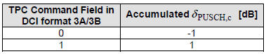
Let's read the tables with the capture in mind. The field accumulationEnabled is True, so this UE works in accumulated mode. A TPC field of 3 then adds 3 dB to f(i), and a field of 0 takes 1 dB off. In absolute mode, the same field values set f(i) directly to -4, -1, 1 or 4 dB, and earlier commands no longer count. DCI format 3A carries a 1-bit command of -1 dB or +1 dB. For FDD, KPUSCH is 4, so a TPC command received in subframe i-4 applies in subframe i.
The two tables above are the Release 14 versions, and 36.213 v19.4.0 keeps the same values. Only the list of DCI formats in the table titles has grown, with format 0C and the short TTI formats 7-0A and 7-0B.
Many people think Power Control would be pretty simple and only in RF related issue. But as you saw in this process, it is pretty complicated process and you have to check a lot of parameters when you do some troubleshooting about the power related issues. You would do a lot of these troubleshooting when you do 36.521 RF conformance testing.
Five terms from three sources : RRC sets PO_PUSCH and α, the UE measures PL, and each grant sets MPUSCH and ΔTF.j says which grant : 0 for semi-persistent, 1 for dynamic, and 2 for the random access response.α below 1 is fractional compensation : cell edge UEs are received weaker, which protects neighbour cells.accumulationEnabled decides the TPC mode : accumulated commands add to f(i), and absolute commands replace it.
PUCCH Power Control
PUCCH carries HARQ-ACK, SR and CSI, and it has no grant of its own. So its formula has no bandwidth term. Instead it adds terms for the PUCCH format and for the number of bits carried. PUCCH also has its own closed loop state g(i), driven by TPC commands in the downlink DCI.
Now let's look into PUCCH. As above, I would rewrite the formula in my text format for easy type writing.
P_PUCCH(i) = min{P_CMAX, P_0_PUCCH + PL + h(n_CQI, n_HARQ) + Delta_F_PUCCH(F) + g(i)}
i : Subframe Number
j : This can be 0 or 1
P_O_PUCCH: P_O_NOMINAL_PUCCH + P_O_UE_PUCCH, where P_O_NOMINAL_PUCCH and P_O_UE_PUCCH came from higher layer(SIB2 or RRC Connection Setup or RRC Connection Reconfiguration).
Delta_F_PUCCH(F) : Provided by Higher Layer(SIB2).

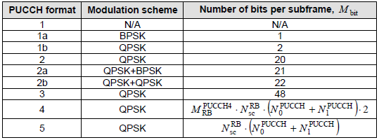
Each of PUCCH format is defined in Table 5.4.1 of 36.211
< 36.211-Table 5.4-1: Supported PUCCH formats >
h(n_CQI, n_HARQ) : A specific number determined by PUCCH format, Number CQI bits, Number of HARQ value (Refer to 5.1.2.1 UE behaviour of 36.213)
For PUCCH format 1, 1a and 1b, h is 0 dB. For format 2, 2a and 2b with normal cyclic prefix, h = 10 log10(nCQI/4) when nCQI is 4 or more, and 0 otherwise. So a longer CQI report gets a little more power.
g(i) : is defined by following equation.
g(i) = g(i-1) + delta_PUCCH(i-4), This shows that the current g(i) is determined by the previous subframe g() and delta_PUCCH of 4 subframe earlier.
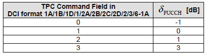
delta_PUCCH is determined by the value carried by DCI format 1A/1B/1D/1/2A/2/3 and the following table of 36.213.
< 36.213 - Table 5.1.2.1-1: Mapping of TPC Command Field in DCI format 1A/1B/1D/1/2A/2B/2C/2D/2/3/6-1A to d_PUCCH values >
< 36.213 - Table 5.1.2.1-2: Mapping of TPC Command Field in DCI format 3A to d_PUCCH values >

The DeltaFList-PUCCH above covers the Release 8 formats only, and it has not changed in 36.331 v19.3.0. Later formats get their ΔF_PUCCH values from extension IEs. PUCCH format 3 and format 1b with channel selection came in Release 10, for carrier aggregation. Formats 4 and 5 came in Release 13, for up to 32 component carriers. Each value is an offset relative to PUCCH format 1a.
Following is based on
UplinkPowerControlCommon-v1020 ::=  SEQUENCE {
    deltaF-PUCCH-Format3-r10            ENUMERATED {deltaF-1, deltaF0, deltaF1, deltaF2,
                                                    deltaF3, deltaF4, deltaF5, deltaF6},
    deltaF-PUCCH-Format1bCS-r10         ENUMERATED {deltaF1, deltaF2, spare2, spare1}
}

UplinkPowerControlCommon-v1310 ::=  SEQUENCE {
    deltaF-PUCCH-Format4-r13            ENUMERATED {deltaF16, deltaF15, deltaF14, deltaF13,
                                                    deltaF12, deltaF11, deltaF10, spare1}    OPTIONAL,   -- Need OR
    deltaF-PUCCH-Format5-13             ENUMERATED {deltaF13, deltaF12, deltaF11, deltaF10,
                                                    deltaF9, deltaF8, deltaF7, spare1}       OPTIONAL    -- Need OR
}

DeltaTxD-OffsetListPUCCH-r10 ::=    SEQUENCE {
    deltaTxD-OffsetPUCCH-Format1-r10        ENUMERATED {dB0, dB-2},
    deltaTxD-OffsetPUCCH-Format1a1b-r10     ENUMERATED {dB0, dB-2},
    deltaTxD-OffsetPUCCH-Format22a2b-r10    ENUMERATED {dB0, dB-2},
    deltaTxD-OffsetPUCCH-Format3-r10        ENUMERATED {dB0, dB-2},
    ...
}
Release 10 also added a term ΔTxD(F') to the formula, for PUCCH sent on two antenna ports. Its value comes from deltaTxD-OffsetListPUCCH-r10, and the listing shows 0 dB or -2 dB for each format. When the UE sends PUCCH on one antenna port, ΔTxD(F') is 0.
No bandwidth term : each PUCCH format has a fixed size, so only the format and the payload change the power.ΔF_PUCCH is the format offset : each value is relative to PUCCH format 1a.g(i) is a separate loop : TPC commands in downlink DCI change PUCCH power only.Later formats use extension IEs : v1020 for format 3 and 1b with channel selection, v1310 for formats 4 and 5.
How is SRS power set ?
SRS carries no data. The eNB uses it to measure the uplink channel, usually to choose the resource blocks and the MCS for the next PUSCH grant. That measurement only works if SRS arrives at a power related to PUSCH. This is why the SRS formula reuses most of the PUSCH terms.
PSRS,c(i) = min{PCMAX,c(i), PSRS_OFFSET,c(m) + 10 log10(MSRS,c) + PO_PUSCH,c(j) + αc(j) PLc + fc(i)} [dBm]
Three terms are the PUSCH terms with j = 1: PO_PUSCH,c(1), αc(1) times PLc, and the PUSCH closed loop state fc(i). So a TPC command for PUSCH moves SRS power as well. MSRS,c is the SRS bandwidth in resource blocks. The one SRS-specific term is PSRS_OFFSET,c(m). It is pSRS-Offset for periodic SRS, m = 0, and pSRS-OffsetAp-r10 for aperiodic SRS, m = 1.
The offset uses different steps depending on Ks. With Ks = 1.25, the value is pSRS-Offset - 3 dB, which gives -3 dB to 12 dB in 1 dB steps. With Ks = 0, it is -10.5 + 1.5 x pSRS-Offset dB, which gives -10.5 dB to 12 dB in 1.5 dB steps. The RRC Connection Setup capture above has pSRS-Offset 0 and deltaMCS-Enabled en0. So that UE sends SRS with an offset of -10.5 dB.
36.213 v19.4.0 clause 5.1.3.1 adds one more case. On a TDD serving cell with no PUSCH or PUCCH configured, the UE has no fc(i) to reuse. SRS then gets its own PO, its own α and its own closed loop state, driven by SRS TPC commands.
SRS follows PUSCH : it uses the same PO_PUSCH, α, PL and f(i), with j = 1.The offset is the SRS-specific part : pSRS-Offset for periodic SRS, pSRS-OffsetAp-r10 for aperiodic SRS.Ks changes the offset scale : 1 dB steps with Ks = 1.25, and 1.5 dB steps with Ks = 0.
PH - Power Headroom
The eNB decides how many resource blocks to grant, but it cannot see the power amplifier of the UE. Power headroom gives it that information. It tells the eNB how much more power the UE could add before it reaches PCMAX.
Now let's look into PH. As above, I would rewrite the formula in my text format for easy type writing.
PH(i) = P_CMAX - [10 log(M_PUSCH(i)) + P_O_PUSCH(j) + alpha(j) PL + Delta_TF(i) + f(i)]
If you see the underlined part, you would notice this is the formula that is used for PUSCH power. So PH(i) means the power difference between P_CMAX and PUSCH power at that subframe. When I say 'PUSCH power' here, it doesn't mean the (really) transmitted PUSCH. It is the estimated (scheduled PUSCH) power. the really transmitted power can never be greater than P_CMAX by 3GPP specification, but the estimated(scheduled PUSCH) power can be lower or greater than P_CMAX.
PH is send from UE MAC layer to eNB periodically as configured by Higher layer message. (Refer to Power Headroom page for the details of PH report)
A negative PH is the case to watch. It means the current grant asks for more power than PCMAX,c. The UE then transmits at PCMAX,c, and the eNB receives it weaker than planned. So the eNB should grant fewer resource blocks or a lower MCS. The UE reports PH in 64 levels of 1 dB, from -23 dB up to 40 dB and above, as 36.133 Table 9.1.8.4-1 defines.
The formula above is Type 1 power headroom, which covers PUSCH only. When the UE can send PUCCH and PUSCH together, it also reports Type 2 power headroom, which subtracts both. The Power Headroom page linked above covers both types, the MAC control element and the triggers.
PH = PCMAX,c minus the required PUSCH power : the UE computes it before any cap is applied.Negative PH means power limited : the grant is too large for this UE.64 levels from -23 dB to +40 dB : 36.133 Table 9.1.8.4-1.
PRACH Power Control
PRACH is the one uplink channel that the UE sends before any closed loop exists. So its power is pure open loop. The full procedure, with power ramping, is on the RACH page. The short version is below, because the same numbers come back in the PUSCH power of Msg3.
This section moves to the section "How is the RACH Preamble Power determined ?" in RACH page.
PPRACH = min{PCMAX,c(i), PREAMBLE_RECEIVED_TARGET_POWER + PLc} [dBm]
MAC sets PREAMBLE_RECEIVED_TARGET_POWER. 36.321 clause 5.1.3 gives it as preambleInitialReceivedTargetPower + DELTA_PREAMBLE + (PREAMBLE_TRANSMISSION_COUNTER - 1) x powerRampingStep. DELTA_PREAMBLE depends on the preamble format, and it is 0 dB for format 0. So each new attempt adds one powerRampingStep, until the eNB answers or the power reaches PCMAX,c.
The open loop PRACH figure above has powerRampingStep dB2, which is 2 dB. In the earlier example, the first preamble went out at -4 dBm. If it gets no answer, the second goes out at -2 dBm, and the third at 0 dBm.
Msg3 then uses the PUSCH formula with j = 2. Its nominal power is PO_PRE + ΔPREAMBLE_Msg3. PO_PRE is preambleInitialReceivedTargetPower, and ΔPREAMBLE_Msg3 is deltaPreambleMsg3 x 2 dB. The closed loop state starts at f(0) = ΔPrampup + δmsg2. Here ΔPrampup is the total ramp-up from the first to the last preamble. The term δmsg2 is the TPC command in the random access response, from -6 dB to 8 dB in 36.213 Table 6.2-1. So Msg3 starts from the power level that finally worked for PRACH.
PRACH power is target plus pathloss : capped at PCMAX,c.Each retry adds powerRampingStep : PREAMBLE_TRANSMISSION_COUNTER counts the attempts.Msg3 keeps the ramp-up : f(0) = ΔPrampup + δmsg2.
What changed in LTE uplink power control after Release 8 ?
The formulas above are the Release 8 formulas, and they are still the core of 36.213. Later releases kept them and added cases around them. Most of the additions come from carrier aggregation, where one UE sends on several uplink carriers from one power budget.
The first change is the serving cell index c. Each serving cell has its own PCMAX,c, its own PLc and its own closed loop state fc(i). For the uplink of the primary cell, the primary cell is the pathloss reference. For a secondary cell, pathlossReferenceLinking selects the reference.
The second change is simultaneous PUCCH and PUSCH. When the UE sends both in the same subframe on a serving cell, the PUSCH cap is no longer PCMAX,c. The cap is the power that PUCCH leaves: the linear value of PCMAX,c minus the linear value of PPUCCH.
The third change is a priority order for the case where the total power is too high. If the sum over all serving cells would exceed the total configured maximum power, the UE keeps PUCCH power first. It then keeps the PUSCH that carries UCI, and it scales down the PUSCH of the other serving cells.
Two more changes act on single parameters. Release 12 added a second power control subframe set for TDD, with tpc-SubframeSet-r12. Subframes in set 2 use their own PO_PUSCH, α and closed loop state. Release 15 added alpha-UE-r15 and p0-UE-PUSCH-r15, and p0-UE-PUSCH-r15 widens the UE-specific range from -8..7 dB to -16..15 dB. The listing below shows these extension IEs.
Following is based on
UplinkPowerControlDedicated-v1020 ::= SEQUENCE {
    deltaTxD-OffsetListPUCCH-r10        DeltaTxD-OffsetListPUCCH-r10    OPTIONAL,   -- Need OR
    pSRS-OffsetAp-r10                   INTEGER (0..15)                 OPTIONAL    -- Need OR
}

UplinkPowerControlDedicated-v1130 ::= SEQUENCE {
    pSRS-Offset-v1130                   INTEGER (16..31)                OPTIONAL,   -- Need OR
    pSRS-OffsetAp-v1130                 INTEGER (16..31)                OPTIONAL,   -- Need OR
    deltaTxD-OffsetListPUCCH-v1130      DeltaTxD-OffsetListPUCCH-v1130  OPTIONAL    -- Need OR
}

UplinkPowerControlDedicated-v1250 ::= SEQUENCE {
    set2PowerControlParameter           CHOICE {
        release                             NULL,
        setup                               SEQUENCE {
            tpc-SubframeSet-r12                 BIT STRING (SIZE(10)),
            p0-NominalPUSCH-SubframeSet2-r12    INTEGER (-126..24),
            alpha-SubframeSet2-r12              Alpha-r12,
            p0-UE-PUSCH-SubframeSet2-r12        INTEGER (-8..7)
        }
    }
}

UplinkPowerControlDedicated-v1530 ::= SEQUENCE {
    alpha-UE-r15                        Alpha-r12                       OPTIONAL,   -- Need OR
    p0-UE-PUSCH-r15                     INTEGER (-16..15)               OPTIONAL    -- Need OR
}
Every term is per serving cell : PCMAX,c, PLc and fc(i).PUCCH has priority : PUSCH is capped by what PUCCH leaves, and PUSCH without UCI is scaled first when power runs out.Extension IEs carry the new parameters : v1020, v1130, v1250 and v1530 add to UplinkPowerControlDedicated without changing it.
YouTube
- Power Control and Interference Management - Research Touch (2021)
Reference
[1] 3GPP TS 36.213 v19.4.0 - clause 5.1, uplink power control, and clause 6, random access procedure
[2] 3GPP TS 36.331 v19.3.0 - UplinkPowerControlCommon, UplinkPowerControlDedicated and their extension IEs, PDSCH-ConfigCommon
[3] 3GPP TS 36.101 v20.0.0 - Table 6.2.2-1, UE power class, and clause 6.2.5, configured transmitted power
[4] 3GPP TS 36.321 v19.3.0 - clause 5.1.3, random access preamble transmission
[5] 3GPP TS 36.133 v19.5.0 - Table 9.1.8.4-1, power headroom report mapping