The eNB schedules the uplink, but it cannot see how much transmit power the UE still has in reserve. If it grants too many resource blocks to a UE near the cell edge, the UE runs out of power and the transmission fails. The Power Headroom Report, or PHR, closes that gap: the UE tells the eNB how far its required power is from its maximum. This page covers what the value means, how it is coded, and when the UE sends it.
Followings are the topics to be covered in this page.
- What is Power Headroom ?
- How does UE report Power Headroom Value ?
- When does UE transmit the Power Headroom Report ?
- Reference
What is Power Headroom ?
Power headroom indicates how much transmission power left for a UE to use in addition to the power being used by current transmission. Simply put, it can be described by a simple formula as below.
Power Headroom = UE Max Transmission Power - PUSCH Power = Pmax - P_pusch
If the Power Headroom value is (+), it indicates "I still have some space under the maximum power" implying "I can transmit more data if you allow".
If the power Headroom value is (-), it indicate "I am already transmitting the power greater than what I am allowed to transmit".
The simple formula above is the idea, and 36.213 v19.4.0 clause 5.1.1.2 gives the exact form. The UE computes a Type 1 report on serving cell c in subframe i, with PUSCH but no PUCCH, as follows.
PH = PCMAX,c(i) - {10 log10(MPUSCH,c(i)) + PO_PUSCH,c(j) + αc(j) PLc + ΔTF,c(i) + fc(i)} [dB]
The term in braces is the PUSCH power that the power control formula asks for, before any limit to PCMAX,c is applied.
This detail explains the negative case. The UE never transmits above PCMAX,c, because it caps its actual power there. A negative PH means that the power the current grant requires is higher than that cap, so the UE is power limited. The eNB should then reduce the number of resource blocks or the MCS for this UE. When the UE has no PUSCH in the subframe, it still reports a value, computed for a reference PUSCH format of one resource block.
36.213 defines three types of power headroom, and the simple formula describes only the first one. The table below lists them.
Type | What it measures | When it is used |
Type 1 | PCMAX,c minus the PUSCH power | every serving cell with uplink |
Type 2 | PCMAX,c minus the PUSCH and PUCCH power together | the PCell, PSCell or PUCCH SCell, when PUCCH and PUSCH can be sent together |
Type 3 | PCMAX,c minus the SRS power | a serving cell where the UE sends SRS without PUSCH |
For formal definition of PH(Power Headroom), see this page.
PH = PCMAX,c minus the required PUSCH power : 36.213 clause 5.1.1.2.Negative PH means power limited : the UE caps its power, and the grant needs more.Three types : Type 1 for PUSCH, Type 2 with PUCCH, Type 3 for SRS.
How does UE report Power Headroom Value ?
PHR is a type of MAC CE(MAC Control Element) that report the headroom between the current UE Tx power (estimated power) and the nominal power. eNodeB (Network) use this report value to estimate how much uplink bandwidth a UE can use for a specific subframe. Since the more resource block the UE is using, the higher UE Tx power gets, but the UE Tx power should not exceed the max power defined in the specification. So UE cannot use much resource block (bandwidth) if it does not have enough power headroom.
You will find the following fig and table from 36.321.
The figure and table below come from 36.321 clause 6.1.3.6. The PHR MAC control element is a single octet: two reserved bits and a 6-bit PH field. It is identified by LCID 11010 on the UL-SCH, which is still the value in 36.321 v19.3.0.
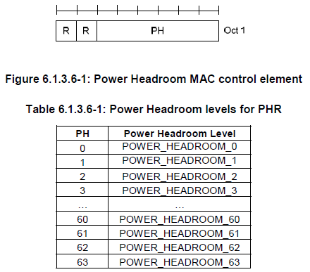
36.321 Figure 6.1.3.6-1 and Table 6.1.3.6-1. The 6-bit PH field gives 64 levels, POWER_HEADROOM_0 to POWER_HEADROOM_63.
How can I figure out real power value from this report value ? You can find the mapping table from 36.133 as shown below.
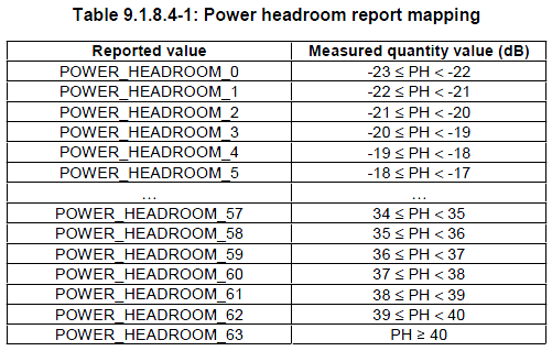
36.133 Table 9.1.8.4-1. Each level is a 1 dB step from -23 dB up to 40 dB and above.
The mapping is a simple offset. A reported value n from 0 to 62 means n - 23 <= PH < n - 22 dB, and value 63 means PH >= 40 dB. For example, a report of 40 means a headroom between 17 and 18 dB, and a report of 20 means between -3 and -2 dB. 36.133 v19.5.0 still uses this table and the same range of -23 to +40 dB.
This one-octet PHR covers only the primary cell. With carrier aggregation, the eNB configures extendedPHR, and the UE sends the Extended PHR MAC control element with LCID 11001. That element carries one PH per activated serving cell with uplink, and it can add the PCMAX,c value the UE used. With dual connectivity, the Dual Connectivity PHR with LCID 11000 also covers the cells of the other cell group.
One octet, 6-bit PH : LCID 11010 in 36.321 clause 6.1.3.6.Value n means n - 23 to n - 22 dB : range -23 to +40 dB, 36.133 Table 9.1.8.4-1.Extended PHR for CA, DC PHR for dual connectivity : LCID 11001 and 11000, one PH per cell.
When does UE transmit the Power Headroom Report ?
A PHR costs uplink resources, so the UE must not send it all the time. It must still send it often enough, and soon enough after a change, for the eNB to schedule with current information. RRC sets this balance with two timers and one threshold.
There are two triggers for PHR (Power Headroom Report).
i) Path Loss Change greater than a certain threshold : UE can calculate the path loss based on RS(Reference Signal) power notified by network and the measured RS power at UE antenna port. If this value changes over a certain threshold UE transmit PHR.
ii) By some peridic Timer.
These triggers are specified in RRC messages (e.g, RRC Connection Setup, RRC Connection Reconfiguration) as shown below.
The capture below shows the phr-Config inside mac-MainConfig of an RRC Connection Reconfiguration. The three fields in the red box are the whole PHR configuration.
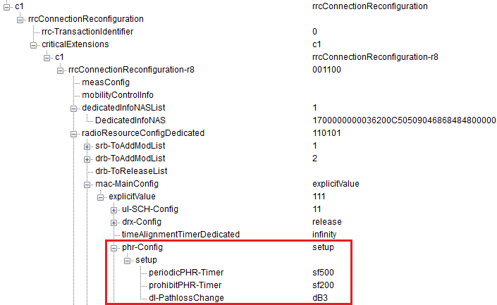
phr-Config in a captured RRC Connection Reconfiguration: periodicPHR-Timer sf500, prohibitPHR-Timer sf200 and dl-PathlossChange dB3.
The values are in subframes, so this UE sends a PHR at least every 500 ms. A pathloss change of more than 3 dB also triggers a PHR, but only when 200 ms have passed since the last one. Both timers restart each time the UE sends a PHR, and every pending trigger is then cancelled. A triggered PHR also waits for an uplink grant with room for the control element, because the PHR has no resource of its own.
The two triggers above are the original ones. 36.321 v19.3.0 clause 5.4.6 lists four more. A PHR is also triggered when RRC configures or reconfigures PHR, and when an SCell with uplink is activated. The addition of a PSCell triggers one too. The last trigger is a change of more than dl-PathlossChange dB in the power backoff for power management, P-MPRc. The P-MPR trigger also respects prohibitPHR-Timer.
The listing below is MAC-MainConfig from 36.331 v19.3.0. phr-Config sits in the Release 8 part, and later extension groups add extendedPHR-r10, dualConnectivityPHR and extendedPHR2-r13. The eNB configures those only when phr-Config is configured.
Following is based on
MAC-MainConfig ::=                  SEQUENCE {
    ul-SCH-Config                       SEQUENCE {
        maxHARQ-Tx                          ENUMERATED {
                                                n1, n2, n3, n4, n5, n6, n7, n8,
                                                n10, n12, n16, n20, n24, n28,
                                                spare2, spare1}     OPTIONAL,   -- Need ON
        periodicBSR-Timer                   PeriodicBSR-Timer-r12   OPTIONAL,   -- Need ON
        retxBSR-Timer                       RetxBSR-Timer-r12,
        ttiBundling                         BOOLEAN
    }                                                               OPTIONAL,   -- Need ON
    drx-Config                          DRX-Config                  OPTIONAL,   -- Need ON
    timeAlignmentTimerDedicated         TimeAlignmentTimer,
    phr-Config                          CHOICE {
        release                             NULL,
        setup                               SEQUENCE {
            periodicPHR-Timer                   ENUMERATED {sf10, sf20, sf50, sf100, sf200,
                                                            sf500, sf1000, infinity},
            prohibitPHR-Timer                   ENUMERATED {sf0, sf10, sf20, sf50, sf100,
                                                                sf200, sf500, sf1000},
            dl-PathlossChange                   ENUMERATED {dB1, dB3, dB6, infinity}
        }
    }                                                               OPTIONAL,   -- Need ON
    ...,
    [[  sr-ProhibitTimer-r9                 INTEGER (0..7)          OPTIONAL    -- Need ON
    ]],
    [[  mac-MainConfig-v1020                SEQUENCE {
            sCellDeactivationTimer-r10          ENUMERATED {
                                                    rf2, rf4, rf8, rf16, rf32, rf64, rf128,
                                                    spare}          OPTIONAL,   -- Need OP
            extendedBSR-Sizes-r10               ENUMERATED {setup}      OPTIONAL,   -- Need OR
            extendedPHR-r10                     ENUMERATED {setup}      OPTIONAL    -- Need OR
        }                                                           OPTIONAL    -- Need ON
    ]],
    [[  stag-ToReleaseList-r11              STAG-ToReleaseList-r11  OPTIONAL,   -- Need ON
        stag-ToAddModList-r11               STAG-ToAddModList-r11   OPTIONAL,   -- Need ON
        drx-Config-v1130                    DRX-Config-v1130        OPTIONAL    -- Need ON
    ]],
    [[  e-HARQ-Pattern-r12                  BOOLEAN                 OPTIONAL,   -- Need ON
        dualConnectivityPHR                 CHOICE {
            release                             NULL,
            setup                               SEQUENCE {
                phr-ModeOtherCG-r12                 ENUMERATED {real, virtual}
            }
        }                                                       OPTIONAL,   -- Need ON
        logicalChannelSR-Config-r12     CHOICE {
            release                             NULL,
            setup                               SEQUENCE {
                logicalChannelSR-ProhibitTimer-r12      ENUMERATED {sf20, sf40, sf64, sf128, sf512, sf1024, sf2560, spare1}
            }
        }                                                           OPTIONAL        -- Need ON
    ]],
    [[  drx-Config-v1310                    DRX-Config-v1310        OPTIONAL,       -- Need ON
        extendedPHR2-r13                    BOOLEAN     OPTIONAL,       -- Need ON
        eDRX-Config-CycleStartOffset-r13    CHOICE {
            release                         NULL,
            setup
                                            CHOICE {
            sf5120                                  INTEGER(0..1),
            sf10240                                 INTEGER(0..3)
            }
        }                                       OPTIONAL    -- Need ON
    ]],
    [[  drx-Config-r13                      CHOICE {
            release                             NULL,
            setup                               DRX-Config-r13
        }                                                           OPTIONAL    -- Need ON
    ]],
    [[  skipUplinkTx-r14                    CHOICE {
            release                             NULL,
            setup                               SEQUENCE {
                skipUplinkTxSPS-r14                 ENUMERATED {true}       OPTIONAL,   -- Need OR
                skipUplinkTxDynamic-r14             ENUMERATED {true}       OPTIONAL    -- Need OR
            }
        }                                                           OPTIONAL,   -- Need ON
        dataInactivityTimerConfig-r14       CHOICE {
            release                             NULL,
            setup                               SEQUENCE {
                dataInactivityTimer-r14             DataInactivityTimer-r14
            }
        }                                               OPTIONAL    -- Need ON
    ]],
    [[  rai-Activation-r14                  ENUMERATED {true}           OPTIONAL    -- Need OR
    ]],
    [[  shortTTI-AndSPT-r15             CHOICE {
            release                         NULL,
            setup                           SEQUENCE {
                drx-Config-r15                  DRX-Config-r15              OPTIONAL, -- Need ON
                periodicBSR-Timer-r15           ENUMERATED {
                                                    sf1, sf5, sf10, sf16, sf20, sf32, sf40,
                                                    sf64, sf80, sf128, sf160, sf320, sf640,
                                                    sf1280, sf2560, infinity}
                                                                            OPTIONAL, -- Need ON
                proc-Timeline-r15               ENUMERATED {nplus4set1, nplus6set1,
                                                nplus6set2, nplus8set2 }    OPTIONAL, -- Need ON
                ssr-ProhibitTimer-r15           INTEGER (0..7)              OPTIONAL -- Need ON
            }
        }                                                                   OPTIONAL, -- Need ON
        mpdcch-UL-HARQ-ACK-FeedbackConfig-r15   BOOLEAN     OPTIONAL,   -- Need ON
        dormantStateTimers-r15              CHOICE {
            release                             NULL,
            setup                               SEQUENCE {
                sCellHibernationTimer-r15           ENUMERATED {
                    rf2, rf4, rf8, rf16, rf32, rf64, rf128, spare}      OPTIONAL,   -- Need OR
                dormantSCellDeactivationTimer-r15   ENUMERATED {
                    rf2, rf4, rf8, rf16, rf32, rf64,
                    rf128, rf320, rf640, rf1280, rf2560,
                    rf5120, rf10240, spare3, spare2, spare1}            OPTIONAL    -- Need OR
            }
        }                                                               OPTIONAL    -- Need ON
    ]],
    [[  ce-ETWS-CMAS-RxInConn-r16               ENUMERATED {true}       OPTIONAL    -- Need OR
    ]],
    [[  offsetThresholdTA-r17                   SetupRelease {OffsetThresholdTA-r17}
                                                                OPTIONAL,   -- Need ON
        sr-ProhibitTimerOffset-r17              SetupRelease {SR-ProhibitTimerOffset-r17}
                                                            OPTIONAL -- Need ON
    ]]
}
periodicPHR-Timer : sf10 to sf1000 or infinity, the regular report.prohibitPHR-Timer with dl-PathlossChange : a pathloss change of 1, 3 or 6 dB triggers a PHR, at most once per prohibit period.More triggers since Release 10 : PHR configuration, SCell activation, PSCell addition and P-MPR change.
Reference
[1] 3GPP TS 36.321 v19.3.0 - clause 5.4.6, Power Headroom Reporting, and clause 6.1.3.6, PHR MAC control element
[2] 3GPP TS 36.213 v19.4.0 - clause 5.1.1.2, Power headroom
[3] 3GPP TS 36.133 v19.5.0 - clause 9.1.8.4, Power headroom report mapping
[4] 3GPP TS 36.331 v19.3.0 - MAC-MainConfig