|
4G/LTE - Reference Signal |
||||||||||||||||||||||||||||||||||||||||||||||||||||||||||||||||||||||||||||||||||||||||||||||||||||||||||||||||||||||||||||||||||||||||||||||||||||||||||||||||||||||||||||||||||||||||||||||||||||||||||||||||||||||||||||||||||||||||||||||||||||||||||||||||||||||||||||||||||||||||||||||||||||||||||||||||||
|
Reference Signal - Downlink
Most of the channels (e.g, DPSCH, DPCCH, PBCH etc) is for carrying a special information (a sequence of bits) and they have some higher layer channel connected to them, but Reference Signal is a special signal that exists only at PHY layer. This is not for delivering any specific information. The purpose of this Reference Signal is to deliver the reference point for the downlink power.
When UE try to figure out DL power (i.e, the power of the signal from a eNode B), it measure the power of this reference signal and take it as downlink cell power. Another important role of reference signal is to help the receiver demodulate the received signal. Since the reference signal is made up of data known to both transmitter and reciever, the reciever can figure out how the communication channel destort the data by comparing the decoded received reference signal and predefined reference signal, and use the result of this comparison to equalize (post process) the recieved user data. The process for the reciever to perform this comparision and figure out the characteristics of a communication channel is called 'Channel Estimation' which is one of the most critical part of many high-end wireless communication like LTE. (If you are really interested in the detailed procedure, I would strongly suggest you to study the basic concept of channel estimation)
These reference signal are carried by multiples of specific Resource Elements in each slots and the location of the resource elements are specifically determined by antenna configuration.
As LTE gets evolved into higher version, we are getting more and more reference signal which is mapped to a specific antenna port. And we are getting more and more confused as a result -:)
Following shows the reference signals supported by each 3GPP version.
For the exact Resource Element locations of each reference signal, refer to following pages.
To implement this signal, you need to go through two steps - signal generation and resource allocation. The details of signal generation and resource allocation would vary on the type of reference signal. In this page, I would focus mostly on Cell Specific Reference Signal to give you general idea.
Followings are the list of topics in this page.
Generation of Reference Signal (Symbol Data of the Reference Signal)
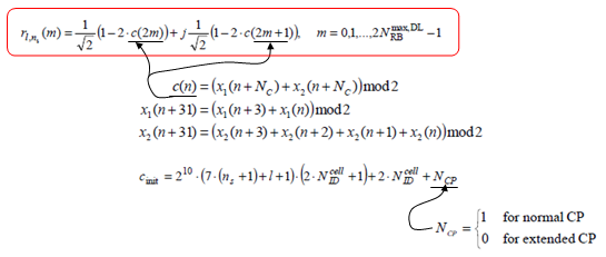
Signal generation is done by the following procedure. You would notice that Cell ID is a key parameter for the sequence and you would guess the sequence will be unique for each Cell ID.
Another thing you would notice here would be that downlink reference signal is a kind of Gold sequence whereas most of UL reference signal and DL Synchronization signal is based on Zadoff Chu sequence. (c(n) is a Gold Sequence(Psuedo Random Sequence)and you see the reference signal is generated by combining the two Gold Sequences). Following equation is based on 36.211 6.10.1.1
< LTE Downlink Refence Signal - Sequence Generation >
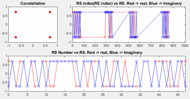
One example of reference signal symbol data is as follows. This is generated by Matlab LTE Toolbox and Refer to Matlab :ToolBox : LTE : Downlink : Cell Specific Reference Signal for the detailed Matlab source. You don't have to try to understand the details of how this is generated (If you really want to understand the details of the signal generation. The only way is to create a program on your own based on the mathematical formula shown above). With this example, you can just build up some intuitive understandings of reference signal properties. See the constellation, it is QPSK, not Zadoff Chu.
< LTE Downlink Reference Signal - Matlab Tool Box >
Resource Allocation (Resource Element Mapping) of Reference Signal
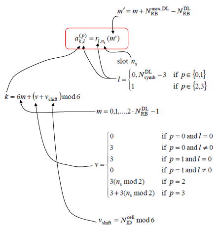
Once you have generated the sequence, next step is to allocate each data point of the sequence to a specified resource elements. That is done by the following process. The resulting location of the process is as shown in Reference Signal section of Downlink Frame Structurepage. Following equation is based on 36.211 6.10.1.2
< LTE Downlink Reference Signal - RE Mapping >
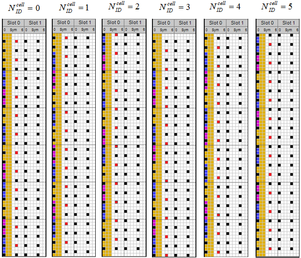
Note 1 : The DL Reference Signal (Cell Specific Reference Signal) is mainly determined by Physical Cell ID. Note 2 : The resource element locations for DL reference signal gets different according to Physical Cell ID, but there is possibility that the reference signal location with two different physical cell ID can be same if (PCI1 mod 6) == (PCI2 mod 6). (PCI stands for Physical Cell ID). It means that you should be careful when you allocate the physical cell ID for multiple cells in a specific area. Following is some of examples of Reference Signal Location with different physical cell IDs. (I created following subframe structure using LTE Resource Grid and edited to fit the topics of this page)
< LTE Downlink Reference Signal - SISO - Location based on Physical Cell ID >
If you examined the location of the reference signal (black cells) shown above, you may ask "According to the RE mapping formula, the reference signal shift is done by ' CellID mod 6' which imply that the reference signal location would repeat at every 6 CellID interval, but according to the grid shown above it seems the location repeats at every 3 CellID interval, not 6. Because of this, UE may experience some degree of RS interference at every 3 CellID intervals even though RS location is shifted by 'CellID mod 6'. (You may see this kind of interference at Intra Frequency Interference between LTE and LTE with Varying Physical Cell ID (PCI) )
Actually this is a kind of illusion. In reality the location repeats at every 6 cellID, but the interval of the reference signal in frequency domain (vertical direction) repeats at every 3 RE(resource element) and all the reference signal is marked in a same color (black). That's why it looks as if it repeat at every 3 CellID. To remove this confusion, I marked the RS at a symbol and marked in different color with 6 REs in vertical direction(I picked only one symbol.. it was too much work to mark different colors manually in Windows Paint :). Now you may (hopefuly) see the shift by 6 interval.
< LTE Downlink Reference Signal - SISO - Location based on Physical Cell ID >
Reference Signal (Antenna Port Number) vs Transmission Mode
Reference Signals are used for various purpose and the type of reference signal being used varies depending on transmission mode. Some of the possible combination of refernece signal and transmission mode are as follows.
Note : ',' indicate "AND". (E.g, p0, p1 means that p0 AND p1 are used) Note : UE Specific means "UE Specific Reference Signal, UE Specific Antenna ports" or is called "DMRS (Demodulation Reference Signal) as well. Note : "No of Tx" means the number of Tx antenna on eNodeB and "No of Rx" means number of Rx antenna on UE Note : TM9 can have much more combinations, but I listed only on the combination I have seen until now (Jun 2014)
|
||||||||||||||||||||||||||||||||||||||||||||||||||||||||||||||||||||||||||||||||||||||||||||||||||||||||||||||||||||||||||||||||||||||||||||||||||||||||||||||||||||||||||||||||||||||||||||||||||||||||||||||||||||||||||||||||||||||||||||||||||||||||||||||||||||||||||||||||||||||||||||||||||||||||||||||||||