For basic introduction to DCI and Release 8 DCI, refer to DCI page. In this page, I would post on the DCIs that is new in LTE advanced. For easy comparison, I put the table showing both release 8 and release 10 DCIs. You can refer to 3GPP 36.212 5.3.3 Downlink control information for the details.
- DCI Formats in Release 10
- Who Schedule Each Component Carriers ?
- The DCI formats that came after Release 10
- Reference
DCI Formats in Release 10
If you are not working on chipset design or early stage of chipset verification, there wouldn't be many cases where you have to look into DCI details. But understanding DCI details would give you more detailed understanding of LTE physical layer. So in terms of study purpose, it is important to understand DCI details.
|
Release 8 |
Release 10 |
|
Format 0 |
Format 0 |
|
Format 1 |
Format 1 |
|
Format 1A |
Format 1A |
|
Format 1B |
Format 1B |
|
Format 1C |
Format 1C |
|
Format 1D |
Format 1D |
|
Format 2 |
Format 2 |
|
Format 2A |
Format 2A |
|
Format 2B |
|
|
Format 2C |
|
|
Format 3 |
Format 3 |
|
Format 3A |
Format 3A |
|
|
Format 4 |
What would be the major difference between Release 8 and Release 10 in terms of DCI format ?
A couple of new DCI format is introduced ? like DCI format 2B,2C and Format 4 ?
Yes. It is a difference. But I think the more important differences is that a new field which is introduced in all Release 10 DCI formats. If you look into the DCI format description in 36.212 and compare the release 8 and release 10. You may find the following difference. In release 10, a new field called 'Carrier Indicator' field which is designed for the scheduling information for multi carrier. If you see in more detail, the bit length of the field is 0 or 3. it means that the field can be obmitted if it is not necessary.
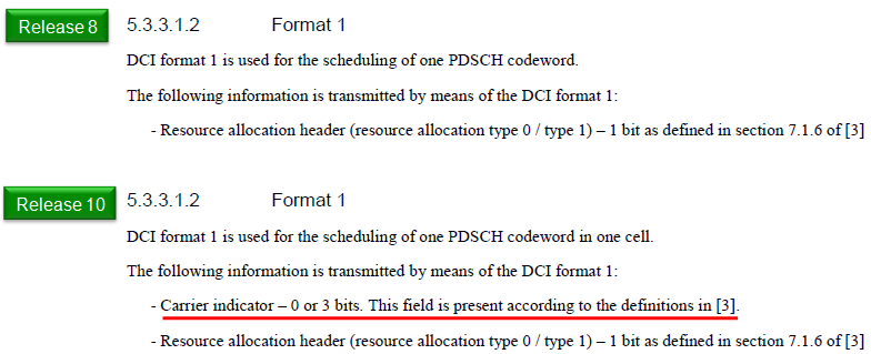
The same clause, 36.212 5.3.3.1.2, in two releases. One line was added and three words were inserted into the sentence above it.
The added line is the one underlined in red : Carrier indicator, 0 or 3 bits, with the clause deferring to its own reference [3] for when the field is present.A second change sits in the opening sentence : Release 8 reads the scheduling of one PDSCH codeword; Release 10 reads one PDSCH codeword in one cell.Carrier indicator is listed first : 36.212 clause 5.3.3.1 maps fields in the order they appear, with the first field at the lowest order information bit a0. The Carrier indicator therefore occupies a0 to a2 whenever it is there.Both changes are still current : 36.212 v19.3.0 carries the Release 10 wording and the Carrier indicator line unchanged.0 or 3 is a length, not a value : when the field is absent the payload is three bits shorter, and payload length is what a UE matches during blind decoding.
The difference between Release 8 DCI format 0 and Release 10 DCI format 0 is as follows. Note that in Release 10 DCI format 0 can specify multicarrier information in CSI field.
One of the out standing difference you see in Release 10 DCI is the existence of 'Carrier Indicator' filed in DCI. But this is not the mandatory field. It may or may not be present in the DCI. Then, question would be how UE can figure out whether the Carrier Indicator field is present or not in the DCI it received ?
The answer is "The existence of Carrier Indicator field in DCI is notified to UE via cif-Presence IE in RRC message."
|
Format 0 (Release 8) |
Format 0 (Release 10) |
|
|
Carrier Indicator |
|
Flag for format0/format1A differentiation |
Flag for format0/format1A differentiation |
|
Hopping flag |
Hopping flag |
|
Resource block assignment(RIV) |
Resource block assignment (RIV) |
|
MCS and RV |
MCS and RV |
|
NDI (New Data Indicator) |
NDI (New Data Indicator) |
|
TPC for PUSCH |
TPC for PUSCH |
|
Cyclic shift for DM RS |
Cyclic shift for DM RS |
|
UL index (TDD only) |
UL index (TDD only) |
|
Downlink Assignment Index (DAI) |
Downlink Assignment Index (DAI) |
|
CQI request (1 bit) |
CSI request (1 or 2 bits : 2 bit is for multi carrier) |
|
|
SRS request |
|
|
Resource allocation type |
What are new for the new DCI format : Format 2B and 2C ? I created a comparative table for you to see the difference between these new format and the existing field.
|
Format 2 (Rel 10) |
Format 2A (Rel 10) |
||
|
Carrier indicator |
Carrier indicator |
Carrier indicator |
Carrier indicator |
|
RA header |
RA header |
RA header |
RA header |
|
Resource block assignment |
Resource block assignment |
Resource block assignment |
Resource block assignment |
|
TPC command for PUCCH |
TPC command for PUCCH |
TPC command for PUCCH |
TPC command for PUCCH |
|
Downlink Assignment Index(TDD only) |
Downlink Assignment Index(TDD only) |
Downlink Assignment Index(TDD only) |
Downlink Assignment Index(TDD only) |
|
HARQ process number |
HARQ process number |
HARQ process number |
HARQ process number |
|
Scrambling identity |
Antenna ports Scrambling identity Number of Layers |
||
|
SRS request(TDD Only) |
SRS request(TDD Only) |
||
|
TB to CW flag |
TB to CW flag |
TB to CW flag |
TB to CW flag |
MCS for TB1 |
MCS for TB1 |
MCS for TB1 |
MCS for TB1 |
NDI for TB1 |
NDI for TB1 |
NDI for TB1 |
NDI for TB1 |
RV for TB1 |
RV for TB1 |
RV for TB1 |
RV for TB1 |
MCS for TB2 |
MCS for TB2 |
MCS for TB2 |
MCS for TB2 |
NDI for TB2 |
NDI for TB2 |
NDI for TB2 |
NDI for TB2 |
RV for TB2 |
RV for TB2 |
RV for TB2 |
RV for TB2 |
|
Precoding information |
Precoding information |
Precoding information |
Precoding information |
The totally new DCI introduced in Release 10, Format 4, carries the information as shown below.
|
Format 4 |
|
Carrier indicator (0 or 3 bits) |
|
Resource block assignment |
|
TPC command for scheduled PUSCH (2 bits) |
|
Cyclic shift for DM RS and OCC index (3 bits) |
|
Downlink Assignment Index (DAI) (2 bits) |
|
CSI request (1 or 2 bits) |
|
SRS request (2 bits) |
|
Resource allocation type (1 bit) |
|
MCS and RV for TB1 (5 bits) |
|
NDI for TB1 (1 bit) |
|
MCS and RV for TB2 (5 bits) |
|
NDI for TB2 (1 bit) |
|
Precoding information and number of layers |
DCI 1 Examples
The format tables above give the field list. The tables below take a real payload and walk it field by field. That is the quickest way to see how a list of bit widths turns into one hex value, and where each field ends up inside it.
Example 1 > DCI Format 1 - 20 Mhz, Value = 0x0FC00005DC40
|
Field |
Value |
Value (Binary) |
CarrierIndicator |
0 (Dec) |
000 |
|
RA header |
RAType0 |
0 |
|
Resource block assignment |
1111110000000000000000000 |
1111110000000000000000000 |
|
MCS |
23 (Dec) |
10111 |
|
HARQ process number |
3 (Dec) |
011 |
|
NDI |
1 |
1 |
|
RV |
0 (Dec) |
00 |
|
TPC |
01 |
01 |
Example 2 > DCI Format 1 - 20 Mhz, Value = 0x2FC00005DC00
|
Field |
Value |
Value (Binary) |
CarrierIndicator |
1 (Dec) |
001 |
|
RA header |
RAType0 |
0 |
|
Resource block assignment |
1111110000000000000000000 |
1111110000000000000000000 |
|
MCS |
23 (Dec) |
10111 |
|
HARQ process number |
3 (Dec) |
011 |
|
NDI |
1 |
1 |
|
RV |
0 (Dec) |
00 |
|
TPC |
0 (Dec) |
00 |
DCI 2A Examples
Format 2A carries two transport blocks, so modulation and coding scheme, new data indicator and redundancy version all appear twice in the field list. The example below shows both copies, and the precoding information field that 2A carries and 2C does not.
Example 1 > DCI Format 2A - 20 Mhz, Value = 0x7E000010BCBC
|
Field |
Value |
Value (Binary) |
|
RA header |
RAType0 |
0 |
|
Resource block assignment |
1111110000000000000000000 |
1111110000000000000000000 |
|
TPC command for PUCCH |
01 |
01 |
|
HARQ process number |
0 (Dec) |
000 |
|
TB to CW flag |
0 |
0 |
|
MCS for TB1 |
23 (Dec) |
10111 |
|
NDI for TB1 |
1 |
0 |
|
RV for TB1 |
0 (Dec) |
00 |
|
MCS for TB2 |
23 (Dec) |
10111 |
|
NDI for TB2 |
1 |
1 |
|
RV for TB2 |
0 (Dec) |
00 |
DCI 2C Examples
Format 2C differs from 2A in one field. Where 2A carries precoding information, 2C carries antenna ports, scrambling identity and number of layers in three bits. It also adds an SRS request and an SRS timing offset, which 2A has neither of.
Example 1 > DCI Format 2C - 10 Mhz, Value = 0x7FFFDC3435C0
|
Field |
Value |
Value (Binary) |
|
RA header |
RAType0 |
0 |
|
Resource block assignment |
11111111111111111 |
11111111111111111 |
|
TPC command for PUCCH |
01 |
01 |
|
HARQ process number |
6 (Dec) |
110 |
|
Ports-SCID-Number of Layers |
0 |
000 |
|
MCS for TB1 |
26 (Dec) |
11010 |
|
NDI for TB1 |
0 |
0 |
|
RV for TB1 |
0 (Dec) |
00 |
|
MCS for TB2 |
26 (Dec) |
11010 |
|
NDI for TB2 |
1 |
1 |
|
RV for TB2 |
3 (Dec) |
11 |
Example 2 > DCI Format 2C - 10 Mhz, Value = 0x1F3FD4202100
|
Field |
Value |
Value (Binary) |
|
RA header |
RAType0 |
0 |
|
Resource block assignment |
00111110011111111 |
00111110011111111 |
|
TPC command for PUCCH |
01 |
01 |
|
HARQ process number |
2 (Dec) |
110 |
|
Ports-SCID-Number of Layers |
0 |
000 |
|
MCS for TB1 |
16 (Dec) |
10000 |
|
NDI for TB1 |
0 |
0 |
|
RV for TB1 |
0 (Dec) |
00 |
|
MCS for TB2 |
16 (Dec) |
10000 |
|
NDI for TB2 |
1 |
1 |
|
RV for TB2 |
0 (Dec) |
00 |
Who Schedule Each Component Carriers ?
When you have multiple Carriers in Carrier Aggregation, you naturally have a question. That is, who (which carrier) will be schedule resource allocation for each sub carriers ? The answer is a configuration choice rather than a fixed rule, and one RRC information element carries it for each secondary cell separately.
There are two types of method we can think of as illustrated below. In one case (Own Scheduling), each component carrier schedules for its own carrier. In the other case (Cross Carrier Scheduling), Primary Compnent Cell (or any specified serving cell) schedules the resource for all the component carriers.
Then you would have another question. How UE knows whether eNB is doing "cross carrier scheduling" or "non cross carrier scheduling" ?
This information is informed to UE via Higher Layer Signaling (RRC Message) as shown below.
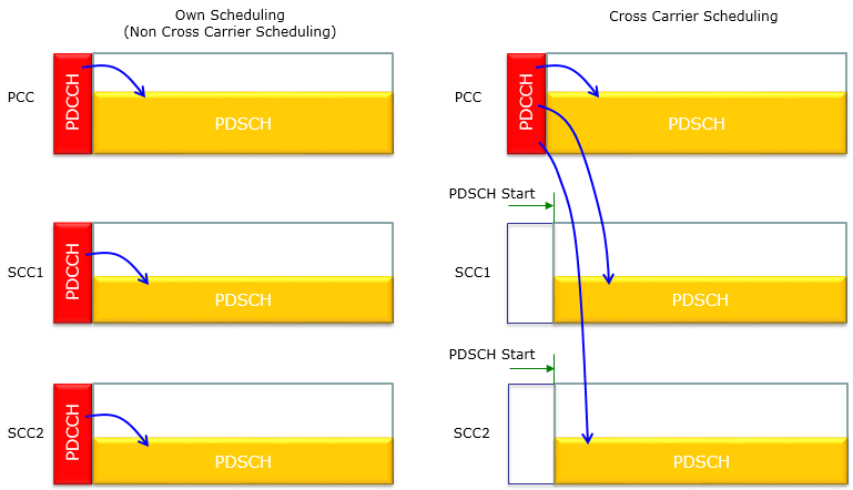
The same three carriers under both arrangements. On the right the two secondary carriers have no PDCCH of their own, and a marker appears where their PDSCH is allowed to start.
On the left every carrier carries its own PDCCH : PCC, SCC1 and SCC2 each show a red PDCCH with an arrow into the yellow PDSCH beside it.On the right only the PCC carries a PDCCH : three arrows leave it, one into the PCC PDSCH and one into each of the two secondary PDSCHs.The secondary carriers gain a PDSCH Start marker : the green arrow labelled PDSCH Start on SCC1 and SCC2 is where their PDSCH begins. The white box before it is the space the missing PDCCH would have used.The PCC keeps its own arrow in both cases : cross carrier scheduling adds the two secondary carriers to the PCC's work rather than moving that work elsewhere.
One information element carries the whole decision, and it is configured per secondary cell. 36.331 puts CrossCarrierSchedulingConfig-r10 inside physicalConfigDedicatedSCell-r10, which is where both of the captures further down find it. Its one member is a CHOICE with two branches, and the branch names say what they are for.
Following is based on
CrossCarrierSchedulingConfig-r10 ::=        SEQUENCE {
    schedulingCellInfo-r10              CHOICE {
        own-r10                             SEQUENCE {                  -- No cross carrier scheduling
            cif-Presence-r10                        BOOLEAN
        },
        other-r10                               SEQUENCE {                  -- Cross carrier scheduling
            schedulingCellId-r10                ServCellIndex-r10,
            pdsch-Start-r10                     INTEGER (1..4)
        }
    }
}

CrossCarrierSchedulingConfig-r13 ::=        SEQUENCE {
    schedulingCellInfo-r13              CHOICE {
        own-r13                             SEQUENCE {                  -- No cross carrier scheduling
            cif-Presence-r13                        BOOLEAN
        },
        other-r13                           SEQUENCE {                  -- Cross carrier scheduling
            schedulingCellId-r13                ServCellIndex-r13,
            pdsch-Start-r13                     INTEGER (1..4),
            cif-InSchedulingCell-r13                INTEGER (1..7)
        }
    }
}
The two branches are not symmetric, and that asymmetry is the answer to the question above. The own-r10 branch carries one boolean. 36.331 describes cif-Presence as indicating whether the carrier indicator field is present, value TRUE, or not, value FALSE, in PDCCH and EPDCCH DCI formats. So a cell can schedule only itself and still ask for the Carrier indicator to be sent.
The other-r10 branch carries two fields instead. schedulingCellId names the cell that signals the downlink allocations and the uplink grants for this secondary cell. pdsch-Start gives the starting OFDM symbol of PDSCH for that secondary cell. It has to be signalled, because that cell carries no PDCCH for the UE to read a control region length from.
The range of pdsch-Start looks wider than it is. 36.331 allows 1 to 4, then narrows the range by bandwidth. Values 1, 2 and 3 apply when the secondary cell's dl-Bandwidth is greater than 10 resource blocks. Values 2, 3 and 4 apply when it is 10 resource blocks or fewer. Three choices are available in either case.
Release 13 added one field to the same structure. CrossCarrierSchedulingConfig-r13 repeats both branches and gives the cross carrier branch cif-InSchedulingCell-r13, an INTEGER from 1 to 7. 36.331 describes it as the CIF value used in the scheduling cell to indicate this cell. Where the carrier indicator field is present, that value is 0. Three bits hold eight codepoints, one carrier aggregation grew past, so the mapping from codepoint to cell stopped being implicit.
One element, configured per secondary cell : CrossCarrierSchedulingConfig sits inside physicalConfigDedicatedSCell, so each SCell is answered separately.The choice is between own and other : own-r10 means the cell schedules itself, other-r10 means another cell schedules it.Only the own branch carries cif-Presence : a self-scheduling cell can still be told to expect a Carrier indicator in its DCI.Only the cross carrier branch carries pdsch-Start : a cell with no PDCCH of its own cannot work out where its PDSCH begins, so it is told.Release 13 added cif-InSchedulingCell : the CIF value that identifies this cell inside the scheduling cell is signalled rather than assumed.
Own Non Cross Carrier Scheduling
If Network (eNB) decided to do Own(Non-Cross carrier) Scheduling, it notifies UE using RRC message as shown below. This is the own-r10 branch of the CHOICE above, and the capture below shows what a UE actually receives when the eNB takes it.
RRC Connection Reconfiguration configuring own scheduling, decoded as a tree,
rrcConnectionReconfiguration
    rrc-TransactionIdentifier: 0
    criticalExtensions: c1 (0)
        c1: rrcConnectionReconfiguration-r8 (0)
            rrcConnectionReconfiguration-r8
                radioResourceConfigDedicated
                    physicalConfigDedicated
                nonCriticalExtension
                    lateNonCriticalExtension: <MISSING>
                    nonCriticalExtension
                        nonCriticalExtension
                            sCellToAddModList-r10: 1 item
                                Item 0
                                    SCellToAddMod-r10
                                        sCellIndex-r10: 1
                                        radioResourceConfigDedicatedSCell-r10
                                            physicalConfigDedicatedSCell-r10
                                                nonUL-Configuration-r10
                                                    crossCarrierSchedulingConfig-r10
                                                        schedulingCellInfo-r10: own-r10 (0)
                                                            own-r10
                                                                .... ..0. cif-Presence-r10: False
Two things in the red lines are worth reading together. schedulingCellInfo-r10 resolves to own-r10. That branch carries no schedulingCellId and no pdsch-Start, because neither has anything to say when a cell schedules itself. Underneath it cif-Presence-r10 reads False. This UE will therefore see no Carrier indicator field in the DCI for this cell, and its DCI payloads are three bits shorter than the format tables above allow for.
Cross Carrier Scheduling
If Network (eNB) decided to do Cross carrier Scheduling, it notifies UE using RRC message as shown below. This is the other-r10 branch, and it is worth comparing line by line with the capture above, because the two differ in only a few lines near the bottom.
RRC Connection Reconfiguration configuring cross carrier scheduling, decoded as a tree,
rrcConnectionReconfiguration
    rrc-TransactionIdentifier: 0
    criticalExtensions: c1 (0)
        c1: rrcConnectionReconfiguration-r8 (0)
            rrcConnectionReconfiguration-r8
                radioResourceConfigDedicated
                    physicalConfigDedicated
                nonCriticalExtension
                    lateNonCriticalExtension: <MISSING>
                    nonCriticalExtension
                        nonCriticalExtension
                            sCellToAddModList-r10: 1 item
                                Item 0
                                    SCellToAddMod-r10
                                        sCellIndex-r10: 1
                                        radioResourceConfigDedicatedSCell-r10
                                            physicalConfigDedicatedSCell-r10
                                                nonUL-Configuration-r10
                                                    crossCarrierSchedulingConfig-r10
                                                        schedulingCellInfo-r10: other-r10 (1)
                                                            other-r10
                                                                schedulingCellId-r10: 0
                                                                pdsch-Start-r10: 3
The red lines have changed branch and gained two fields. schedulingCellInfo-r10 now resolves to other-r10, schedulingCellId-r10 reads 0, which is the primary cell, and pdsch-Start-r10 reads 3. There is no cif-Presence line anywhere in this capture, because the field belongs to the branch that was not taken. A UE reading this message learns which cell will schedule this SCell and where that SCell's PDSCH begins, and nothing else about the Carrier indicator from here.
The drawing below takes the same message and puts the pdsch-Start value on a symbol ruler, which is where its effect is visible.
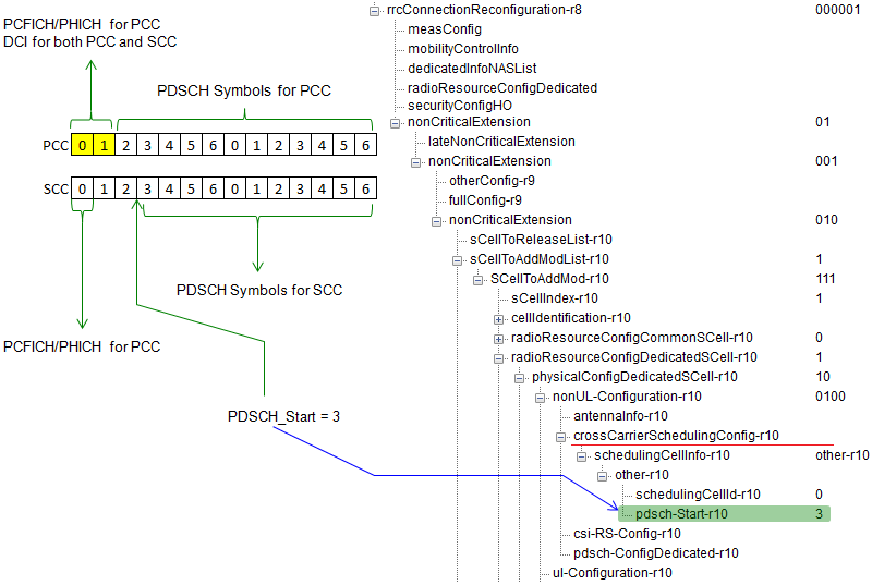
The decoded message on the right and its effect on the left. The value 3 is a symbol index, and it is where the secondary cell's PDSCH is allowed to begin.
Symbols 0 and 1 of the PCC do two jobs : the label on them reads PCFICH / PHICH for PCC and DCI for both PCC and SCC. That is cross carrier scheduling drawn one subframe at a time.The PCC PDSCH bracket starts at symbol 2 : the primary cell's own control region ends and its data begins right after it.The SCC PDSCH bracket starts at symbol 3 : one symbol later than the PCC, and that offset is the signalled value rather than anything the SCC broadcast.The blue arrow names the source : it runs from PDSCH_Start = 3 on the ruler to pdsch-Start-r10 3 in the tree, highlighted green, under crossCarrierSchedulingConfig-r10.The tree is the same path as the capture above : sCellToAddModList-r10, SCellToAddMod-r10, radioResourceConfigDedicatedSCell-r10, physicalConfigDedicatedSCell-r10, nonUL-Configuration-r10.
The DCI formats that came after Release 10
The list above stops where Release 10 stopped, and 36.212 did not. The format list in clause 5.3.3.1 has roughly doubled since then, and the additions arrived in families rather than one at a time. Knowing which family a format belongs to is usually enough to know what it is for.
Four families account for nearly all of the growth. Licensed-Assisted Access added Formats 0A, 0B, 4A and 4B, which schedule PUSCH on an LAA SCell, and the B variants schedule several subframes at once. Sidelink added Formats 5 and 5A, which schedule PSCCH and carry SCI fields for PSSCH. Coverage enhancement added the 6-x family. Short TTI operation added the 7-x family.
The last two families are substitutions rather than extras. 36.212 says that for a BL/CE UE, format 0 is replaced by format 6-0A, and the 6-x formats travel on MPDCCH rather than PDCCH. The 7-x formats travel on SPDCCH and schedule a slot or a subslot instead of a whole subframe. Each family has its own control channel, which is why neither reuses the numbering of the formats it stands in for.
The Carrier indicator did not spread to all of them, and the pattern is worth reading. Formats 0, 0A, 0B, 1, 1A, 1B, 1D, 2, 2A, 2B, 2C, 2D, 4, 4A and 4B all carry it at 0 or 3 bits. Formats 0C, 1C, 3, 3A, 3B, 5, the whole 6-x family and the whole 7-x family carry none. Format 5A is the one exception. It carries a Carrier indicator of 3 bits with no zero length option, so there the field is always present.
Format 2D is the one addition that belongs to the family this page already covers. It takes the field list of 2C and adds a two bit PDSCH RE Mapping and Quasi-Co-Location Indicator. A UE needs that field when its PDSCH may come from more than one transmission point.
The table below lists what 36.212 v19.3.0 says each of the later formats schedules, and whether it carries a Carrier indicator.
|
Format |
What 36.212 v19.3.0 says it schedules |
Carrier indicator |
Format 0A |
PUSCH in an LAA SCell, or activating and releasing AUL transmission |
0 or 3 bits |
Format 0B |
PUSCH in each of multiple subframes in an LAA SCell |
0 or 3 bits |
Format 0C |
PUSCH in one UL cell |
none |
Format 2D |
one PDSCH, with a PDSCH RE Mapping and Quasi-Co-Location Indicator that 2C does not carry |
0 or 3 bits |
Format 3B |
a group of TPC commands for SRS transmissions by one or more UEs |
none |
Format 4A |
PUSCH in an LAA SCell with multi-antenna port transmission mode |
0 or 3 bits |
Format 4B |
PUSCH with multi-antenna port transmission mode in each of multiple subframes in an LAA SCell |
0 or 3 bits |
Format 5 |
PSCCH, and it carries SCI format 0 fields for PSSCH |
none |
Format 5A |
PSCCH, and it carries SCI format 1 fields for PSSCH |
3 bits, always present |
Format 6-0A |
PUSCH in one UL cell, ACK feedback and preconfigured UL resources, on MPDCCH |
none |
Format 6-0B |
the same as 6-0A, for the other coverage enhancement mode |
none |
Format 6-1A |
one PDSCH codeword per TTI in one cell, and a random access procedure started by a PDCCH order |
none |
Format 6-1B |
one PDSCH codeword per TTI in one cell, and SC-MCCH change notification |
none |
Format 6-2 |
paging, direct indication, and one PDSCH codeword carrying SC-MCCH |
none |
Format 7-0A |
PUSCH with slot or subslot duration in one UL cell, on SPDCCH |
none |
Format 7-0B |
PUSCH with slot or subslot duration with multi-antenna port transmission mode |
none |
Format 7-1A to 7-1G |
one PDSCH codeword with slot or subslot duration in one cell, seven variants of the same job |
none |
The later formats arrived in families : Licensed-Assisted Access, sidelink, coverage enhancement and short TTI account for nearly all of them.Two families are substitutions : 36.212 replaces format 0 with format 6-0A for a BL/CE UE, and the 6-x and 7-x families ride MPDCCH and SPDCCH rather than PDCCH.The Carrier indicator stayed with carrier aggregation : almost every format in the 0, 1, 2 and 4 families carries it, with 0C and 1C the exceptions. The 3, 6-x and 7-x families carry none at all, and in the 5 family only 5A has one.Format 5A is the one unconditional case : its Carrier indicator is 3 bits with no zero length option.Format 2D extends the family on this page : it is 2C plus a two bit PDSCH RE Mapping and Quasi-Co-Location Indicator.
Reference
Two specifications carry everything quoted on this page. 36.212 defines the DCI formats and the order their fields are mapped in. 36.331 defines the RRC element that decides which of them a UE has to expect on which carrier.
- [1] 36.212 : 3GPP - E-UTRA; Multiplexing and channel coding, v19.3.0. Clause 5.3.3.1 holds the DCI format list and the field mapping rule.
- [2] 36.331 : 3GPP - E-UTRA; Radio Resource Control, v19.3.0. CrossCarrierSchedulingConfig-r10 and its Release 13 successor are quoted above.
- [3] DCI : the Release 8 DCI page on this site, which the introduction above points at.