Literally speaking, Intelligent Reflective Surface is a kind of reflective surface with intelligence. Obviously, a reflective surface is a surface which reflect a wave to another direction. The point here is the term 'intelligence', What does it mean by 'intelligent' in this context.
You will also meet the same idea as Reconfigurable Intelligent Surface, RIS, which is the name used in reference [4] and in most recent papers. Let's first see what 'intelligent' means for a reflector. Then we will look at why an array of such reflectors is useful, how one element is built, how much power the surface can return, and what still makes it hard.
- What makes a reflective surface intelligent ?
- Motivation
- How to Implement ?
- How much power does an IRS return ?
- Challenges ?
- Reference :
- YouTube :
What makes a reflective surface intelligent ?
Let me try explain on this with a simple example as illustrated below. Take a look at a situation shown on the left. A radio wave emitted from a tower gets reflected as indicated by the arrows. As shown here, the reflected wave does not reach to the UE in this setup and reflected angle. If I want the reflected wave to hit the UE, what should I do ?
We may think of two options as labelled as Option (A) and Option (B) as below. The option (A) would be the one that everybody can think of. We may rotate the reflector mechanically so that the reflected wave reach the UE. Sound simple. But this does not sound 'intelligent'.
If there is another way to change the direction of the reflected wave to arbitrary direction without mechanically rotating the surface. It can be called as 'intelligent' and this technology have been implemented by a special type of the surface material, the property of which can be changed electronically.
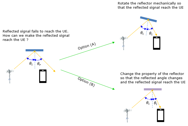
Figure 1. Two ways to steer a reflection toward the UE. Option (A) moves the surface, and option (B) changes the surface so that the reflection angle itself changes.
The left drawing is an ordinary mirror : the reflection angle θr equals the incident angle θi, and the reflected ray passes beside the UE.Option (A) keeps the mirror law : the rotated surface has a new normal, and both angles are still θi about that normal.Option (B) breaks the mirror law : the surface stays where it is, so the reflected angle must differ from the incident angle. The drawing labels both angles θi, but for option (B) the reflected one is a different angle, θr.
Motivation
Why IRS ? What is the motivation for IRS ? With the single reflective surface even if it is intelligent, there wouldn't be many fancy things we can do. But if we make an array of such a elements, we may be able to do some fancy things. For example, let's suppose we have a simple array of such a surface element, we can let the reflected wave from all of the elements reach to the same point (e.g UE) by setting different reflection angle for each of the elements as illustrated below.
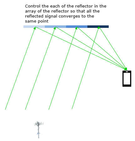
Figure 2. A one dimensional array of reflecting elements. Each element is set differently, so that all the reflected rays meet at the UE.
If we extend the array from 1 dimension to 2 dimension as shown below, we may form a beam in 3D space to point to a certain direction.
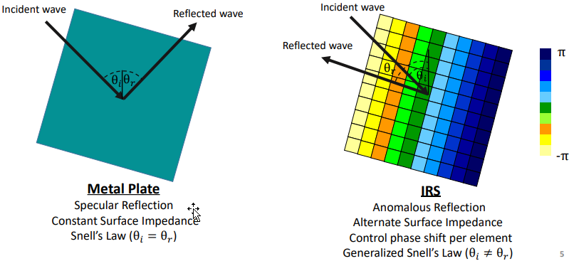
Image Source : Intelligent Reflecting Surfaces: Fundamentals and Applications
Figure 3. A metal plate follows Snell's law, θi = θr. An IRS applies a different phase shift on each element, from -π to π in the colour scale, and the phase gradient bends the reflection away from the mirror direction.
The colour stripes in Figure 3 are the key. Each element adds its own phase shift to the reflected wave, and the phase changes steadily across the surface. The generalized Snell's law in Figure 3 links that phase gradient to the reflection angle. For a wave that arrives along the normal, θi = 0, the law reduces to sin θr = (λ/2π) x dΦ/dx, where dΦ/dx is the phase change per unit length along the surface.
Let's put numbers in at 28 GHz, where λ = 10.7 mm. With elements spaced λ/2 apart, a reflection at θr = 30 deg needs a phase step of 90 deg from one element to the next. A 45 deg reflection needs 127 deg per element, and 60 deg needs 156 deg per element. So the controller steers the beam by changing the phase step, and nothing on the surface moves. This is the same idea as a phased array antenna, except that the surface reflects a wave instead of radiating its own. See Phased Array System.
Ultimate motivation for IRS is illustrated below. If we have wide walls of IRS and paste them on the walls of surrounding buildings, we may use those buildings as a magic mirror to focus the waves from all the different directions to focus on a specific UE.
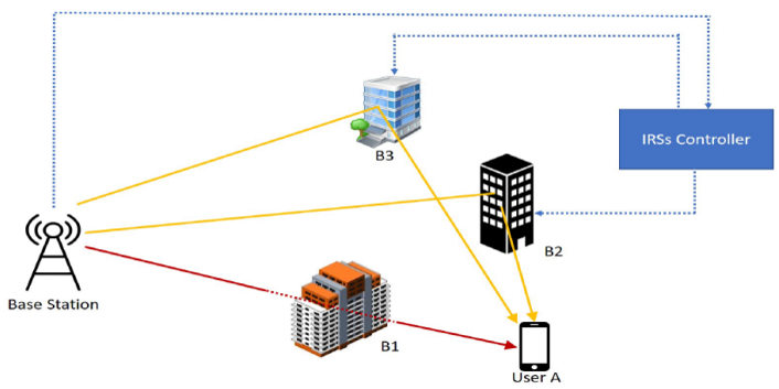
Image Source : Intelligent Reflecting Surfaces: Fundamentals and Applications
Figure 4. IRS panels on buildings create new paths around a blocked direct path. A controller sets each panel so that its reflection reaches the user.
The direct path is blocked : the red line from the base station to User A passes through building B1.B2 and B3 carry the IRS panels : the yellow lines show the reflected paths that reach User A around B1.The IRSs Controller links the base station and the panels : the dotted blue lines are control connections, not radio paths for user data.
How to Implement ?
The most common way of implementing the IRS (Intelligent Reflective Surface) as far as I learned is to use the surface elements which can be represented as an equivalent circuit as follows and each of the electronic components can be controlled by electronic control signal. Depending on how to set the values for each of the electronic components, the reflective property (e.g, reflection angle) changes.
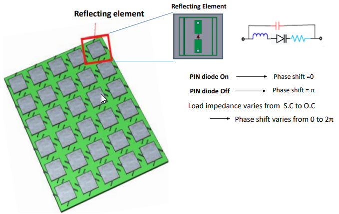
Figure 5. A reflecting element with a PIN diode. Switching the diode changes the load impedance of the element, and the load impedance sets the phase of the reflected wave.
Why does a load impedance set a phase? Each element behaves like a small antenna terminated by a load ZL. The reflection coefficient of that load is Γ = (ZL - Z0)/(ZL + Z0), the same formula as in Impedance matching. For a pure reactance ZL = jX, |Γ| is always 1, and the phase is π - 2 arctan(X/Z0). A short circuit, X = 0, gives π. An open circuit, X going to infinity, gives 0. X = +Z0 gives π/2, and X = -Z0 gives 3π/2. So a reactance that runs from short to open covers the full circle, which is what the note on the right of Figure 5 says.
A PIN diode has only two states, so one diode gives a 1-bit element with two phases. The array then cannot apply the exact phase each element needs, and the beam loses some gain. For a large surface with evenly spread target phases, the table below gives the average loss from phase quantization.
Control bits |
Phase states |
Quantization loss |
1 |
0, π |
3.9 dB |
2 |
4 states, π/2 apart |
0.9 dB |
3 |
8 states, π/4 apart |
0.2 dB |
The loss is 20 log10 of sinc(1/2b) for b bits, with sinc(x) = sin(πx)/(πx), and a quick simulation with random target phases gives the same values. Real elements have one more limit. The resistor in the equivalent circuit absorbs part of the power, so |Γ| is below 1, and the absorption changes with the phase state.
Load impedance sets the reflection phase : a lossless reactive load reflects all the power and only moves its phase.1-bit elements are simple but cost about 3.9 dB : two bits reduce the loss to about 0.9 dB.Real elements are not lossless : the reflected amplitude depends on the phase state because the element resistance absorbs power.
How much power does an IRS return ?
A mirror in Figure 1 sends the whole reflection toward one direction, but a real IRS is a passive panel of small elements. So we must ask how much power actually reaches the UE, and how the surface size and position change it. Two effects decide the answer, and they work in opposite directions.
The first effect is coherent combining, and it helps. Suppose each of N elements delivers a wave of the same amplitude at the UE. When the phases are aligned, the amplitudes add, so the total amplitude is N times one element and the power is N2 times. Doubling the number of elements therefore adds 6 dB. With random phases, the powers add instead, and doubling adds only 3 dB. The phase control in the section above is what earns the extra 3 dB per doubling.
The second effect is the double hop, and it hurts. The wave travels from the base station to the surface and then from the surface to the UE. In the far field of the surface, the received power falls with the square of the product d1 x d2 of the two distances. Take a 200 m link. A surface 10 m from one end gives d1 x d2 = 1900, and a surface in the middle gives 10000. The surface near the end returns 14.4 dB more power. So an IRS works best close to the base station or close to the users.
A repeater is the active alternative. It amplifies and forwards the signal, so it is not limited by the double hop in the same way, but it needs power and adds its own noise. The network-controlled repeater, NCR, was introduced in 5G Rel-18. See 6G TDoc Air Interface for proposals to support both NCR and RIS from the start of 6G.
Aligned phases give N2 power : doubling the surface adds 6 dB when the phases are controlled.The double hop costs the most in the middle : received power falls with (d1 x d2)2 in the far field.Place the surface near one end of the link : in the 200 m example, 10 m from one end beats the middle by 14.4 dB.
Challenges ?
In terms of the concepts, it would sound fancy, but there would be challenges to apply this to the communication system. Some of the challenges are listed below.
How high frequency it can cover ?
Personally I don't think this technology would be used in 5G since we already have most of the technology that we need to make 5G work. IRS is gaining attention as a component technology in 6G. But we don't see much research results of IRS for such a high frequency (e.g, sub-terahertz frequency). Most of the research result as far as I read as of now (Sep 2022) is about IRS implmentation in relatively low frequencies. The obstacles to be overcome is to find proper material and control algorithm for IRS to work in 6G candidate frequencies.
The numbers in the implementation section show why frequency is hard. At 28 GHz, a λ/2 element is only 5.4 mm wide, and at 300 GHz it is 0.5 mm. The switch in each element must work at that frequency and still fit inside that size. Reference [4] is about RIS for terahertz links.
Channel State Information Mechanism
For this technology to work, it is likely to use so many reflective surface elements in a wide pannel. To properly tune each elements of those surfaces, we need to know of the exact channel state information for the specific target UE. Then the challenge is to invent a smart mechnism for obtaining the channel state information for the UE without too much of overhead.
The difficulty comes from the passive design. A passive element has no receiver, so the surface cannot measure the channel by itself. The base station and the UE must estimate the combined channel through the surface, and the number of unknowns grows with the number of elements. One of the videos below, on learning to reflect and to beamform without explicit channel estimation, studies exactly this problem.
High frequency means very small elements : a λ/2 element is 5.4 mm at 28 GHz and 0.5 mm at 300 GHz.A passive surface cannot measure the channel : the base station and the UE must estimate it, and the overhead grows with the number of elements.
Reference :
[1] Intelligent Reflecting Surfaces: Physics, Propagation, and Pathloss Modeling (Dec 2019)
[2] Intelligent Reflecting Surface: Practical Phase Shift Model and Beamforming Optimization (Feb 2020)
[3] Intelligent Reflecting Surfaces: Fundamentals and Applications
[4] Terahertz Reconfigurable Intelligent Surfaces (RISs) for 6G Communication Links (2022)
YouTube :
- Fundamentals of Intelligent Reflecting Surfaces (Mar 2020)
- Reconfigurable intelligent surfaces: Myths and realities (Mar 2020)
- A Programmable Wireless World With Reconfigurable Intelligent Surfaces (Jul 2020)
- Ep 3. Reconfigurable Intelligent Surfaces [Wireless Future Podcast] (Nov 2020)
- 6G Vision for 2030+ (Nov 2020) - Intelligent Reflective Surface Demo @ 21:45
- Ep 9. Q/A on Reconfigurable Intelligent Surfaces (Feb 2021)
- Reconfigurable Intelligent Surfaces: A Signal Processing Perspective (Mar 2021)
- Reconfigurable Intelligent Surfaces for Wideband Communications: Challenges and Possible Solutions (2021)
- Reconfigurable Reflecting Surfaces for 5G/6G | University of Surrey (2021)
- One World SP Seminar (12/01/2021) - Prof. Marco di Renzo (CNRS) - One World SP (2021)
- Learn to Reflect and to Beamform Without Explicit Channel Estimation - AusCTW (2021)
- 6GIC CLICK- Reconfigurable Intelligent Surfaces | University of Surrey - (2022)
- Reconfigurable Intelligent Surfaces 2.0 for 6G: Beyond Diagonal Phase Shift Matrices - Prof. Bruno Clerckx (2022)
- 6G Talk: RIS as Wireless System Enhancement | Professor Markku Juntti (2023)
- Kiren Mukkavilli/Tingfang Ji - Passive MIMO for Sustainable 6G Networks - Center for Wireless Communications at UC San Diego (2023) // Recommended
- Saeed Khosravirad - Reconfigurable intelligent surfaces: opportunity or trap? - Center for Wireless Communications at UC San Diego (2023) // Recommended
- Reconfigurable Intelligent Surfaces: Channel Modeling, System Design and Practical Measurements - Ibrahim Yildirim (2023)
- Wavefront Manipulation Attack via Programmable mmWave Metasurfaces: from Theory to Experiments - ACM WiSec (2023)