An array antenna combines many small radiating elements into one antenna. All elements handle the same signal, and the way their fields add up in space decides where the energy goes. This page starts with what an array is and why it focuses energy. Then it explains how a phase shift on each element steers the beam, and how the array relates to beamforming. The worked numbers use a uniform linear array with half wavelength spacing, because that case is easy to check by hand.
- Array Antenna, what is it ?
- Why Array Antenna ?
- What is Phased Array Antenna ?
- Why Phased Array Antenna ?
- What is the relation between Array Antenna and BeamForming ?
- Reference
- YouTube
Array Antenna, what is it ?
What is Array Antenna ? The answer lies within the name itself. It is a type of antenna that is made up of an "array of antenna" (not a single antenna). Each single antenna within the array antenna is called 'Antenna Element'. There are various examples of array antenna. Only a few of the examples are shown below.
The photographs below cover a wide range of sizes. The top row shows large radar arrays, where the elements fill the face of a building or a flat panel. The middle row shows printed arrays: rows of patches with their feed lines, a feed network drawn in a circuit design tool, and a small module mounted in an anechoic chamber for measurement. The bottom row shows arrays built from wire and rod elements, such as grid reflectors and Yagi antennas mounted together on one frame.
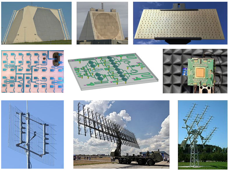
Figure 1. Examples of array antennas. The element type and the size change from one example to the next. In every case, the antenna is a set of similar elements placed in a regular pattern.
The element is the building block : a patch, a dipole, a slot or a Yagi can serve as the element. For identical elements, the pattern of the whole array is the element pattern multiplied by the array factor. So the element still limits the pattern at wide angles.The spacing is set in wavelengths : elements usually sit about half a wavelength apart. At 3.5 GHz, half a wavelength is about 43 mm. At 28 GHz, it is about 5.4 mm. This is why a mmWave array fits inside a phone, while a low frequency radar array covers a building.The arrangement gives the array its name : elements on a line form a uniform linear array, ULA. Elements on a grid form a uniform rectangular array, URA. The ULA and URA pages plot the patterns of both kinds in Matlab.
Why Array Antenna ?
The main motivation of using Array antenna is that it can focus the radiation to a specific direction. Focusing the radiation to a specific beam is called 'Beamforming'.
Let's put a number on that focusing. Suppose N identical elements share a fixed total power and radiate with the same phase. In the broadside direction, the fields from all elements arrive in phase, so their amplitudes add. Each element carries 1/N of the power, so its field amplitude is 1/√N of a single element fed with all of it. N such fields add to √N times that field, and the power density grows N times. So the peak gain of the array over one element is N, or 10 log10(N) dB.
Two things change when you count the power differently. In an active array, each element has its own power amplifier, so the total transmit power also grows N times. The EIRP then grows N2 times. On the receive side, the wanted signal adds coherently while the noise of each element adds in power. So the SNR after combining improves N times, which is the same 10 log10(N) dB.
The gain is not free. The energy that goes into the main lobe is taken from other directions, so the beam becomes narrower as N grows. The table below lists both numbers for a uniform linear array with half wavelength spacing, pointed at broadside. The beamwidth is the half power beamwidth, computed from the array factor alone.
Elements N |
Array gain |
Half power beamwidth |
4 |
6.0 dB |
26.3 deg |
8 |
9.0 dB |
12.8 deg |
16 |
12.0 dB |
6.4 deg |
64 |
18.1 dB |
1.6 deg |
Each doubling of N adds 3 dB and halves the beamwidth : the beamwidth is close to 0.886 x 2/N radians for half wavelength spacing, which gives 12.7 deg for N = 8.A uniform array has sidelobes near -13 dB : the first sidelobe of the array factor is -12.8 dB for N = 8 and about -13.3 dB for large N. Tapering the element amplitudes lowers it, but widens the main lobe.Array gain adds to the element gain : the 9.0 dB of an 8 element array comes on top of the gain of one patch or dipole.
What is Phased Array Antenna ?
When each of the antenna elements within the array has some way to change the phase of the signal, the array antenna is called 'Phased Array Antenna'. (The phase shift can be done for a specific fixed value by a fixed electric circuit or can be done for arbitray value by variable phase shift or digital signal processing).
Let's see why a phase shift moves the beam. Take elements spaced d apart along a line, and a target at angle θ0 from broadside. The path from each element to a far target differs from the path of the next element by d sinθ0. That extra path is a phase difference of 2πd sinθ0/λ. If each element is fed with a progressive phase shift β that cancels this difference, all fields arrive in phase at θ0. The beam then points at θ0.
The diagram below shows a 4 element array steered to the right. Each element has its own phase shifter, and one splitter or combiner connects all of them to a single transmit or receive chain.
Figure 2. Steering a linear array with a progressive phase shift. The phase shifters add 0, β, 2β and 3β, so all elements form one wavefront tilted by θ0. No part of the antenna moves.
The steering phase is β = -2π(d/λ)sinθ0 : the sign depends on which end of the array is taken as the reference. With d = λ/2 and θ0 = 30 deg, β is -90 deg, so the four elements get 0, -90, -180 and -270 deg. For θ0 = 60 deg, β is about -155.9 deg.The spacing limits the scan range : if d is too large, a second main lobe, a grating lobe, appears in another direction. The array avoids it when d is not more than λ/(1 + |sinθ0|). For a 30 deg scan, d must stay below 0.67λ. Half wavelength spacing meets the limit for any scan angle.A phase shift equals a time delay at one frequency only : take an array steered to 30 deg at 28 GHz with phase shifters. The same phases point the beam at about 31.2 deg at 27 GHz, and at about 28.9 deg at 29 GHz. This is beam squint. Wideband arrays use true time delay elements to avoid it.The phase can come from a circuit or from DSP : the parenthesis in the definition above lists the options. A fixed network gives fixed beams, a variable phase shifter gives any angle, and digital signal processing applies the phase as a complex weight on the samples.
Why Phased Array Antenna ?
With Phased Array Antenna, you can change the shape of the radiation pattern (beam) in more diverse way or change the direction of the beam electronically (i.e, without moving the antenna array physically).
Electronic steering has two practical advantages. The first is speed: the beam moves as soon as the phase shifters are reloaded, so it can change from one radar pulse or one scheduling slot to the next. The second is reliability: there is no motor, no gear and no rotating joint to wear out. A large array also fails gradually, because the loss of a few elements lowers the gain a little and does not stop the antenna.
Steering has a cost, though. Seen from the scan direction, the array looks shorter by a factor of cosθ0. So the beam becomes wider and the gain drops as the beam moves away from broadside. The element pattern also falls off at wide angles, which adds a further loss. For the 8 element array above, the computed half power beamwidth is 12.8 deg at broadside, 14.8 deg at 30 deg and 28.8 deg at 60 deg. For that reason, one flat panel usually covers a sector, and a full circle needs several panels.
Where the phase is applied also matters. In analog beamforming, one phase shifter per element feeds one transmit or receive chain, so the array forms one beam at a time. In digital beamforming, every element has its own chain and converter, so the baseband can form many beams at once. Hybrid beamforming sits in between: groups of elements share analog phase shifters, and a few digital chains combine the groups. Many mmWave devices use analog or hybrid designs, because a converter per element costs power.
The beam moves without moving the antenna : reloading the phase shifters is enough, and nothing mechanical is involved.The beam widens as it scans : the effective aperture shrinks by cosθ0, so a panel works best near broadside.Analog, digital and hybrid differ in how many beams exist at once : analog gives one beam per chain, digital gives as many as the baseband can compute, and hybrid trades the two.
What is the relation between Array Antenna and BeamForming ?
The term 'Array Antenna' is focused on the physical structure of the antenna and the term 'BeamForming' is focused on the mechanism by which the radiation pattern from a antenna get focused on a specific direction. Since BeamForming is implemented by Array Antenna in most application, you would see Array antenna and beamforming goes hand in hand in most of technical papers.
I strongly recommend you to study on BeamForming as well when you study on Array Antenna.
In beamforming terms, the phase shift on element n becomes one complex weight wn. Changing only the phase of the weights steers the beam, as Figure 2 shows. Changing the amplitude as well shapes the beam. For example, a taper that lowers the edge elements reduces the sidelobes, and the main lobe becomes wider. A digital beamformer can also compute weights that place a null toward an interferer. It can even send different data streams on different beams, and that is where beamforming meets MIMO.
The array is the hardware, the weights are the beamforming : one array can form a fixed beam, a steered beam or several beams, depending on the weights it is given.Phase steers and amplitude shapes : phase only weights move the main lobe, and amplitude weights trade sidelobe level against beamwidth.5G NR relies on both : a gNB sweeps SSB beams over a set of directions with its antenna array, and the UE reports which beam it receives best.
Reference
[1] Algorithms to Antennas: A Blog for 5G, Radar, and EW RF Engineers (Microwave&RF)
[3] Algorithms to Antenna: Achieve System Performance Goals with Less Hardware (Microwave&RF)
[4] Algorithms to Antenna: Designing an Antenna Array (Microwave&RF)
[5] First 5G mmWave Antenna Module for Smartphones
[6] Qualcom QTM052
[7] Qualcomm's First 5G mmWave Chipset: SDX50M and QTM052
[8] Antenna Integrated Radio Unit Description-Ericsson AIR 6488
[9] Advanced Antenna System for 5G (5G America)
YouTube
The videos below cover array antennas from theory and simulation to built hardware and test ranges. Several of them show phased arrays for radar and 5G, and a few show printed patch arrays.
- Design Example: Phased-Array Antennas
- Hackaday Supercon - HunterScott : Why Phased Arrays are Cool and How to Build One
- Analog Beamforming—What is it and How Does it Impact Phased-Array Radar and 5G?
- 5G Phased Array Antennas - Simulation Essentials
- Simulation-Enabled 5G Antenna Design
- The art and challenges in designing Printed Antenna Arrays
- Microstrip Antenna Arrays - SixtySec
- Antenna Arrays
- Antenna Arrays Part 2
- Design Example: In-Situ Analysis of Patch-Array Antenna
- ESMA 256 Element Antenna Demonstration
- SatixFy's Antenna Micro Test Range (AMTR) demonstration
- 5G Beam-Steering with EM/Circuit Excitation and Co-simulation in PathWave ADS
- Simulation of Phased Array Radar Systems
- Slot Antenna | Types of Antenna | Antenna and Wave Propagation | AWP |Vaishali Kikan | Lecture 25 |
- RF Elements Webinar – Learn About Beam Efficiency
- RF Elements: AS-5-20 Array Sector Antenna Introduction