WiFi OffLoad means a kind of handover (or selection/reselection) technology between Non-WiFi network and WiFi Network. It is not a new concept, but it has become hot issue recently especially after LTE network is wide spread. So when we say WiFi Offloading, it usually mean that WiFi Offload (handover) between LTE network and WiFi network.
Let's put this in 3GPP terms before we go further. TS 23.402 treats WiFi as a non-3GPP access to the EPC, so the PDN GW stays the anchor when the UE moves between LTE and WiFi. Because the anchor does not change, the UE can keep its IP address across the move. TS 24.302 defines the UE procedures for this, and TS 33.402 defines the security. There is also a simpler case, non-seamless WLAN offload. In that case the UE sends traffic straight from the WLAN to the Internet, without the EPC, and the IP address is not preserved.
Followings are the list of topics that will be discussed in this page. I will describe these topic at very high level as an introduction. I would write separate pages depending on the subject.
- WiFi Offload Protocol Related Notes
- Who is triggering the offload ?
- Overall Network Arichitecture for WiFi Offload
- 'Trusted vs Untrusted' Access
- ANDSF, what is it ? why we need it ?
- Session Mobility
- Interplay between ANDSF and Mobility
- Interplay between UE and ANDSF
- What kind of Information are provided by ANDSF
- Typical Traffic Flow via 'Untrusted Non-3GPP Access'
- Reference
WiFi Offload Protocol Related Notes
Followings are WiFi Offload Protocol Related pages on sharetechnote. Thease are mainly for the initial procedure of the offloading happening right before data traffic starts. Actually these initial procedure is the important topics you need to understand and the procedure for real data traffic is not special for WiFi Offload. For example, if the WiFi Offloading happens for Voice call, only the initial procedure (i.e, Handover process) is specifically designed for WiF offloading. Once the handover protocol is completed, the data protocol is same as regular IMS protocol.
- WiFi OffLoad : CheckList
- WiFi OffLoad : Overall Procedure of Untrusted Data Path Setup
- WiFi OffLoad : ePDG Discovery
- IKEv2
I suggest you read them in the order of the procedure itself. The CheckList page comes first, because it lists the UE settings that decide whether the UE even starts the procedure. The Data Path Setup page then shows the whole sequence, from WLAN association through DHCP and DNS to the IPsec tunnel. The ePDG Discovery page and the IKEv2 page explain in detail the two steps where most failures happen.
All four pages cover the untrusted path through the ePDG. This page gives the context around them: who decides to move, which network nodes are involved, and how the operator steers the UE with ANDSF.
Who is triggering the offload ?
Just from the user's point of view, we can think of several user model as described below. The answer matters in practice, because it tells you which node to check first in a log: the UE, the eNB or ANDSF.
< Case 1 > UE-Initiated WiFi OffLoading
i) UE is in connected mode with LTE network while there is no WiFi Network Available.
ii) UE start seeing WiFi signal.
iii) User switch the connection from LTE to WiFi Network.
Note : I should say this is over-simplified description. You may have a lot of questions boggling in your mind. In what criteria, user decided to switch from LTE to WiFi ? You said 'Switch the connection to WiFi ?'. Exactly what do you mean by 'Switching' ? What is the exact mechanism ? etc. I will get back to these question later.. for now, just get the big picture.
< Case 2 > Network-Initiated WiFi OffLoading
i) UE is in connected mode with LTE network while there is no WiFi Network Available.
ii) UE start seeing WiFi signal.
iii) Network tells UE to switch the connection from LTE to WiFi Network.
Note : I should this is over simplified description as well. You would have a lot of questions for this as well. How network knows that UE is seeing WiFi Signal ? How network notify UE to switch to WiFi ? etc.
Let's map the two cases onto the specifications. In the handover procedures of TS 23.402 clause 8, the UE starts the move. For example, in the LTE to WiFi handover later on this page, the UE attaches to the WLAN and starts the IKEv2 tunnel itself. So Case 2 does not mean that the network sends a handover command to WiFi, the way an eNB does for an LTE handover.
Instead, the network steers the UE's own decision. The first tool is ANDSF, which gives the UE operator policies about which access to prefer. The second tool is the RAN rules of Release 12, where E-UTRAN provides thresholds in SIB17 or by dedicated signalling, and the UE compares them with its LTE and WLAN measurements. TS 23.402 names both tools for access network selection and traffic steering between 3GPP access and WLAN.
Release 13 moves closer to a real Case 2. With RAN Controlled LTE-WLAN Interworking, RCLWI, the eNB sends RRCConnectionReconfiguration to tell a UE in RRC_CONNECTED to steer traffic to WLAN. The UE passes that command to its upper layers, and the upper layers decide which traffic can be offloaded. LTE-WLAN Aggregation, LWA, gives the eNB even more control, because the eNB itself uses WLAN radio resources for the UE's bearers (TS 36.300 clause 22A).
Now let's think about business issues... about money. What is the motivation to go for WiFi offloading?
What would be your motivation to Switch your communication channel from LTE to WiFi while you are in connection?
For mobile phone user it may help him to get access to wider bandwith and probably in lower cost or free
For mobile network operators it would help reduce the load on the LTE network by offloading the subscriber to WiFi network
Then you may ask "What about the money for the network operator? " they may not be able to charge for WiFi network usage as much as for LTE network but they may be able to get some gain from load balancing and still keep some portions of the money from the mobile user by directing to switch to the WiFi network serviced by the mobile network operator (not free WiFi)
This is just tip of WiFi Offload and I will keep updating this page as I have further chance.
If you are eager to know the details before I update, I would recommend following documents.
- 3GPP TR 22.934 Feasibility study on 3GPP system to Wireless Local Area Network (WLAN) interworking
- 3GPP TS 23.261 IP flow mobility and seamless Wireless - Local Area Network (WLAN) offload;Stage 2
- 3GPP TS 23.402 Architecture enhancements for non-3GPP accesses
- 3GPP TS 33.402 3GPP System Architecture Evolution (SAE);Security aspects of non-3GPP accesses
The UE starts the handover in both cases : the handover procedures of TS 23.402 have no network command that moves a UE from LTE to WiFi.The network steers through policy : ANDSF policies and the Release 12 RAN rules shape the UE's own decision.RCLWI and LWA are RAN features : from Release 13 the eNB can command WLAN steering or aggregate WLAN under LTE.
Overall Network Arichitecture for WiFi Offload
Now let's get just a little bit deeper into WiFi Offload mechanism. The first thing you need to understand is overall network architecture related to WiFi Offload. You would see various network architecture depending various use model.
Following is the architecture showing the combination of following figures in 23.402.
- Figure 4.2.2-1: Non-Roaming Architecture within EPS using S5, S2a, S2b
- Figure 4.2.3-3: Roaming Architecture for EPS using S8 – S2c - Home Routed
- Figure 4.2.3-4: Roaming Architecture for EPS using S5, S2a, S2b – Local Breakout
Most of the components are the ones that you are already familiar with normal LTE/IMS operation. The component and interfaces that you need to pay attention for WiFi Offload would be as follows : (Don't try to memorize it.. just try to follow the path with pen whenever you are studing any specific use case).
- Untrusted Non-3GPP IP
- Trusted Non-3GPP IP
- ePDG
- 3GPP AAA Server
- SWu, SWn,Swa,SWm,STa,S2c,S2a,S2b
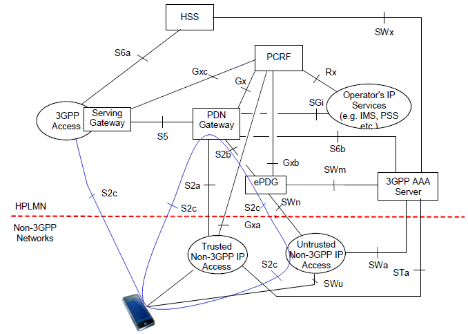
The red dashed line splits the drawing into the HPLMN above and the non-3GPP networks below. The PDN Gateway stays the anchor for all three paths, and each path reaches it on its own reference point. The breakdown below follows the reference point definitions of TS 23.402 v19.0.0.
S2a : user plane with related control and mobility support between the Trusted Non-3GPP IP Access and the PDN Gateway.S2b : the same role between the ePDG and the PDN Gateway. This is the leg that the untrusted path uses.S2c : mobility support between the UE and the PDN Gateway itself. The blue lines from the phone show that S2c can run over trusted, untrusted or 3GPP access.SWu : the IPsec tunnel between the UE and the ePDG. The UE sets it up, and it carries the user data.SWn : the link between the Untrusted Non-3GPP IP Access and the ePDG. Traffic for a UE-initiated tunnel is forced towards the ePDG on this link.SWa and STa : the AAA links from the untrusted access and from the trusted access to the 3GPP AAA Server. STa also carries mobility parameters.SWm and SWx : SWm carries tunnel authentication and authorization between the ePDG and the 3GPP AAA Server. SWx connects the 3GPP AAA Server to the HSS.S6b, Gxa and Gxb : S6b connects the PDN Gateway to the 3GPP AAA Server. Gxa carries policy from the PCRF to the trusted access, and Gxb is still not specified in this release.
Now let's think of how WiFi network get anchored to 3GPP network (e.g, LTE network). There are a couple of different ways to do it but if I am allowed for another oversimplifcation, it can be only two categories. One is through 'Trusted Access Point' and the other one is through 'Non-Trusted Access Point'. You can think of 'Trusted' as that the WiFi Security is protected by the 3GPP network, so you would not need any separate authentication process between 3GPP and Non-3GPP Network (WiFi). 'Non-Trusted' means that the WiFi Security is not protected by the 3GPP network, so you need to go through separate authentication process between 3GPP and Non-3GPP Network (WiFi)
The PDN Gateway is the common anchor : LTE, trusted WiFi and untrusted WiFi all end at the same PDN Gateway, which is why the IP address can survive a move.The untrusted path adds the ePDG : the UE builds an IPsec tunnel on SWu, and the ePDG connects to the PDN Gateway on S2b.The 3GPP AAA Server authenticates every non-3GPP path : it talks to the access on STa or SWa, to the ePDG on SWm and to the HSS on SWx.
'Trusted vs Untrusted' Access
If you see the network structure for Non-3GPP Access, you would see two different path. One is through 'Trusted' path and the other one is through 'Untrusted' path.
What does it mean by 'Trusted' ? Who trust who ?
'Trust' in this case is that 'Operator TRUST the access(path)'. It doesn't necessarily mean (may or may not mean) 'UE trust the path'.
The biggest difference between trusted access and untrusted access would be the requirement of authentication requirement.
In trusted access, UE would not need any separate authentication/security process when it switches from 3GPP access to non-3GPP access (WiFi) since UE already has gone through this process when it was camping on the 3GPP access and network trust the process and assume that the non-3GPP access can be protected by the same security procedure. In this access, it is highly likely that Network Operator distribute their own WiFi Access points and let UE get access through those Access Point.
On the other hand, in Untrusted access, network would require UE to go through additional authentication/security process when UE switches to non-3GPP access and use special IP tunneling mechanism (e.g, IPSec) for data transaction. In most of this case, UE would get WiFi access via public WiFi access point and those access points would be anchored to ePDG.
One correction to the simple picture above is needed. A trusted access still authenticates the UE. TS 33.402 clause 6 runs EAP-AKA' between the UE and the 3GPP AAA Server over the trusted access, through STa. What the trusted access does not need is the extra IPsec tunnel to an ePDG. On the untrusted path, the UE authenticates twice in the worst case. The first time is an optional access authentication with the WLAN. The second time is EAP-AKA inside IKEv2 towards the ePDG, as in TS 33.402 clause 8.
So how does the UE know which kind of access it is on? TS 24.302 says the home PLMN operator decides the trust relationship. The UE learns it in one of two ways. The first is a dynamic indication, the AT_TRUST_IND attribute, which the 3GPP AAA Server sends during EAP-AKA or EAP-AKA' access authentication. The second is a policy that the home operator has pre-configured in the UE. The dynamic indication wins when both exist. If the UE has neither, it treats the access as untrusted and uses the ePDG.
Trust is the operator's decision : the home PLMN operator decides it, not the UE and not the WLAN owner.Trusted still means authenticated : a trusted access runs EAP-AKA' through STa, but it does not need an IPsec tunnel to an ePDG.Unknown means untrusted : with no AT_TRUST_IND and no matching policy, the UE uses the untrusted procedures of TS 24.302 clause 6.5.
ANDSF, what is it ? why we need it ?
ANDSF stands for 'Access Network Discovery and Selection Function'. This is a set of services that would answer to following questions. Both questions come up before any handover starts, so ANDSF works on the selection side and leaves the data path to the ePDG and the PDN GW.
- I am at such and such location now, which network (3GPP or Non-3GPP) are available for me ?
- Now my mobile phone detected 3GPP network and WiFi network, which network I have to get access to ?
Why does the UE need a server for these answers? The UE could scan for WiFi all the time, but that costs battery. The UE also cannot see the operator's preferences from the radio alone. For example, the operator may want voice traffic to stay on LTE while video goes to its own hotspots. ANDSF is the place where the operator writes those preferences down and hands them to the UE.
ANDSF is an optional network element in TS 23.402. The one in the home network is the H-ANDSF, and the one in a visited network is the V-ANDSF. The UE talks to it over the S14 reference point, which runs above IP. So the UE can reach ANDSF over LTE, over WiFi through the ePDG, or even over non-seamless WLAN offload.
ANDSF can give the UE several kinds of information. The first is access network discovery information, a list of networks near the UE, such as WLAN SSIDs with their validity area. The second is the Inter-System Mobility Policy, ISMP, for a UE that uses one access at a time. The third is the Inter-System Routing Policy, ISRP, for a UE that can use LTE and WiFi at the same time. Later releases add the Inter-APN Routing Policy, IARP, and the WLAN Selection Policy, WLANSP.
How does the UE find the ANDSF? In the home network, the operator can configure the H-ANDSF address in the UE, or the UE can find it by DNS or by DHCP. In a visited network, TS 24.302 says the UE uses DNS. The same policies can also sit on the UICC or be pre-configured on the ME. In that case the UE uses them in a fixed order. Information from the ANDSF server comes first, then the UICC, then the ME pre-configuration.
ANDSF carries operator policy, not radio measurements : it tells the UE which access the operator prefers, where and when.ANDSF is optional : TS 23.402 also supports RAN rules without ANDSF for steering between LTE and WLAN.The server wins over static copies : ANDSF server data takes precedence over the UICC, and the UICC over the ME pre-configuration.
Session Mobility
Mobility is a mechanism of switching between 3GPP (e.g LTE) and non-3GPP (e.g, WiFi) networks. Largely there are two methods you can think of, NBM (Network Based Mobility - Network Initiated) and HBM(Host Based Mobility - UE Initiated)
Be careful with the words Network Initiated and UE Initiated here. They describe who sends the mobility signalling, not who decides the handover. In both methods, the UE decides to move and starts the procedure. The difference is which node then talks to the PDN GW about the new path.
In NBM, the network does the mobility signalling for the UE. On the untrusted path, the ePDG sends a Proxy Binding Update with PMIPv6, or a Create Session Request with GTP, to the PDN GW on S2b. The trusted access does the same on S2a. The UE itself runs no mobility protocol. It only asks, during IKEv2, for the IP address it already had.
In HBM, the UE runs the mobility protocol itself. TS 23.402 lists DSMIPv6 on S2c and MIPv4 FACoA as the host based options. With DSMIPv6, the WLAN or the ePDG gives the UE a local address, which the UE uses as its Care-of Address. The PDN GW then acts as the Home Agent and keeps the Home Address stable.
Which one is used? The operator can configure one method statically in the UE and the network. Otherwise, IP Mobility Management Selection, IPMS, picks it during authentication. The UE indicates the modes it supports, and the network selects one. TS 24.302 also shows how the UE asks for address preservation with NBM on the untrusted path. For an initial attach, the UE sends an empty INTERNAL_IP4_ADDRESS or INTERNAL_IP6_ADDRESS attribute in the IKEv2 CFG_REQUEST. For a handover attach, it puts its previously allocated address in that attribute instead.
NBM keeps the UE simple : the ePDG or the trusted access signals to the PDN GW, and IP address preservation comes through S2a or S2b.HBM puts DSMIPv6 in the UE : the UE registers its Care-of Address with the PDN GW over S2c.The CFG_REQUEST tells initial attach from handover : an empty address attribute means initial attach, and the old address means handover.
Interplay between ANDSF and Mobility
ANDSF and the mobility mechanism answer two different questions. ANDSF decides where the traffic should go, and the mobility mechanism decides how the traffic gets there. The link between them depends on what the UE can do with more than one access at the same time.
The diagram below puts the two sides next to each other. On the left, ANDSF holds data and information in the MO, and rules and policies as ISMP and ISRP. On the right are two mobility mechanisms, IFOM and MAPCON. Red lines link the policy entries on the left to the mechanisms on the right.
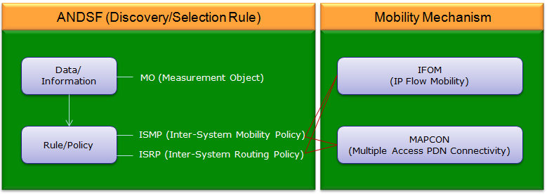
MO is a Management Object : the drawing expands MO as Measurement Object, but in ANDSF it is the OMA DM Management Object of TS 24.312.ISMP is for a UE that uses one access at a time : TS 23.402 applies ISMP when the UE is neither IFOM nor MAPCON capable, or has both capabilities disabled.ISRP is the policy that drives IFOM and MAPCON : its rules for IFOM route IP flows, its rules for MAPCON route whole PDN connections, and its rules for non-seamless WLAN offload pick traffic that leaves the EPC.IFOM moves single IP flows : TS 23.261 builds IP flow mobility between 3GPP and WLAN on DSMIPv6, so one PDN connection can have some flows on LTE and others on WiFi.MAPCON moves whole PDN connections : TS 23.402 spells it Multi Access PDN Connectivity. For example, the IMS PDN connection can stay on LTE while the internet PDN connection goes over WiFi.
So when you read an ANDSF log, check the UE capability first. A UE with IFOM and MAPCON disabled uses ISMP, and it ignores the ISRP rules even if ANDSF sends them.
Interplay between UE and ANDSF
The UE and ANDSF exchange the ANDSF MO with OMA DM, and the question is who opens the session. TS 24.302 defines two models for this, push and pull. The diagram below shows both of them.
In the upper box, the push method runs between the UE, a WAP Gateway and ANDSF. ANDSF sends an OMA-DM Notification Message to the WAP Gateway, the WAP Gateway forwards it to the UE, and the UE answers with an SMS Confirm. In the lower box, the pull method runs directly between the UE and ANDSF, with an HTTP POST carrying OMA-DM Generic and an HTTP RESPONSE carrying OMA-DM Status.
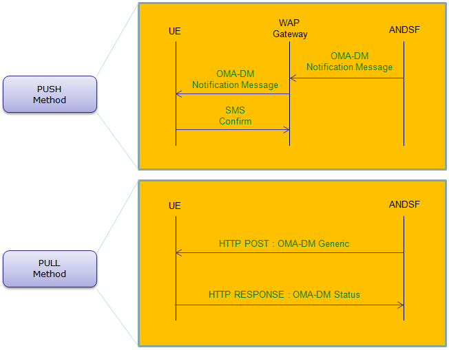
Push is only a wake-up : the notification SMS tells the UE to connect. After a valid ANDSF notification SMS, the UE itself establishes the secure data connection to ANDSF.Push works over 3GPP access only : TS 24.302 uses WAP Push for this model, and TS 23.402 notes that push may not work in all scenarios.Pull is a UE query : the UE opens an OMA DM session with a Generic Alert. The type urn:oma:at:ext-3gpp-andsf:1.0:provision asks for all available information.The HTTP client is always the UE : in OMA DM the UE sends the HTTP POST and ANDSF answers in the HTTP response. The pull arrows in the drawing point the other way, so read them as the direction of the management content.The session is protected at transport level : TS 24.302 uses PSK TLS with a GBA-based key for pull, and GBA Push for push, as specified in TS 33.402.
What kind of Information are provided by ANDSF
It provides huge set of information. so it is hard to describe everything in this section. You can get the full sets of information about this in 3GPP as summarized below
The specification that I referred to is ETSI TS 124 312 V11.6.0 (2013-04). Since this is relatively early stage, it is highly likely that new items or revision will be added as it goes to new version. Try following up the latest specification as it roll out.
Figure 4.2.1~Figure 4.2.8 : Tree diagram of MO ANDSF information
Annex A (informative): an example of minimum set of ANDSF MO DDF
The prediction above was right. In TS 24.312 v19.0.0 the tree diagrams now run from Figure 4.2.1 to Figure 4.2.15, and Annex A holds the full ANDSF MO DDF. The Management Object Identifier is urn:oma:mo:ext-3gpp-andsf:1.0. The table below lists the main nodes under the ANDSF root and what each one gives the UE.
Node |
What it gives the UE |
Policy |
ISMP rules, a prioritized list of accesses for a UE that uses one access at a time |
DiscoveryInformation |
access networks near the UE, for example WLAN SSIDs, with their validity area |
UE_Location |
the position of the UE, which the UE can report to the ANDSF server |
ISRP |
routing rules in three containers: ForFlowBased for IFOM, ForServiceBased for MAPCON and ForNonSeamlessOffload |
UE_Profile |
UE information that the ANDSF server can read to tailor what it provides |
WLANSP |
rules for selecting and reselecting a WLAN access network |
IARP |
rules that pick a PDN connection, or non-seamless WLAN offload, for matching IP flows |
RuleSelectionInformation |
VPLMNs whose own rules the UE should prefer when it roams |
HomeNetworkPreference |
help in selecting a WLAN, a service provider and an ePDG, accepted only from the H-ANDSF |
The HomeNetworkPreference node matters for the ePDG pages linked above. TS 24.302 lets the home operator put the ePDG configuration information there, under the ePDG node. The UE then uses that configuration first, before the same information on the USIM or on the ME.
The MO keeps growing : read the current TS 24.312 rather than the V11.6.0 tree, because nodes such as IARP, WLANSP and HomeNetworkPreference came later.The UE ignores what it does not support : TS 24.312 tells the UE to ignore unsupported child nodes of the ANDSF root, so a partial implementation still works.
Typical Traffic Flow via 'Untrusted Non-3GPP Access'
One of the 'Untrusted' access that attracts the widest attention as of this writing (Feb 2014) is through ePDG as shown below. Overall procedure and data path are as follows.
i) UE is in 3GPP network (e.g, LTE)
ii) UE is triggered to switch to WiFi network
iii) UE switches to WiFi network and goes to authentication server first (follow the red line)
iv) After completing the authentication process, start user data transaction through the green path.
Most important step in this traffic flow is Authentication and Security Association step at the initial step where UE start communicating with 3GPP network over Non-3GPP Access (e.g, WiFi Access Point). This initial step is described in detail in IKE based 3GPP 33.402 section.
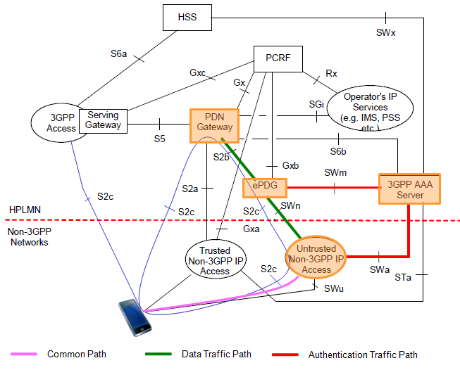
Common Path, in pink : the radio link from the phone to the Untrusted Non-3GPP IP Access. Both the authentication and the data use it.Authentication Traffic Path, in red : from the untrusted access to the 3GPP AAA Server on SWa, and from the ePDG to the 3GPP AAA Server on SWm. The SWa leg is used only if the WLAN runs 3GPP-based access authentication, which is optional.Data Traffic Path, in green : from the untrusted access to the ePDG, and from the ePDG to the PDN Gateway on S2b. Between the UE and the ePDG the data runs inside the IPsec tunnel of SWu.
Following is one example of WiFi Offloading From LTE network to WiFi Network. In terms of protocol implementation on UE and Test equipment side in early phase of testing (As of Jun 2014), the colored part has become the major target of validation. According to my experience on testing, step 4 and step 8 is the most tricky step to come over. Especially, passing step 4 (IKEv2) is the most difficult part to step over.
Handover from LTE to WiFi
Following diagram shows overall procedure for the case where UE start communication from LTE and switch to WiFi Network (Untrusted Non-3GPP). This case assumes that UE is connected to LTE before the switch (Handover) and not connected in WiFi. If UE is already connected both to LTE and WiFi before this handover, it will skip the step 2~9 and directly jump to step 10.
< 3GPP 23.402 Figure 8.2.3-1: Handover from 3GPP Access to Untrusted Non-3GPP IP Access with PMIPv6 on S2b >
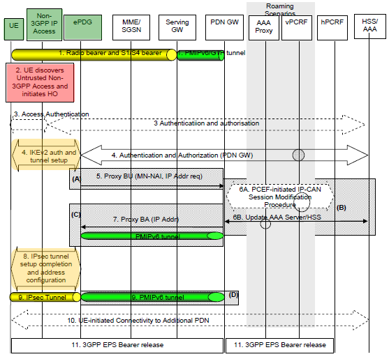
Step 1 : UE is initially attached to LTE network. (In the most of testing situation with test equipment, WiFi on UE turned off at this stage).
Step 2 : (In the most of testing situation with test equipment, we turn on WiFi on UE at this time). UE start detecting WiFi network and initiate switching process to WiFi network.
Step 3 : (This may be an optional step) UE and EPC perform Access authentication process. => This corresponds to 33.402 6 Authentication and key agreement procedures
Step 4 : UE and ePDG performs IKEv2 tunnel establishment procedure. (See the details in IKE page or 3GPP 33.402). Following is the decription for this step in 23.402 and I add some comments to relate 23.402 and 33.402.
- The IKEv2 tunnel establishment procedure is started by the UE. The ePDG IP address to which the UE needs to form IPsec tunnel with is discovered as specified in clause 4.5.4.
- After the UE is authenticated, UE is also authorized for access to the APN. The procedure is as described in TS 33.402.
- As part of access authentication the PDN GW identity is sent to the ePDG by the 3GPP AAA server. => This corresponds to step 5 of 33.402 Figure 8.2.2-1
- If the UE supports IP address preservation during handover from 3GPP Access to the untrusted non-3GPP IP access, the UE shall include its address (IPv4 address or IPv6 prefix /address or both) allocated when it's attached to 3GPP Access into the CFG_Request sent to the ePDG during IKEv2 message exchange. => This corresponds to step 2 of 33.402 Figure 8.2.2-1
Step 5 : ePDG sends the Proxy Binding Update message to PDN GW. Followings are conveyed in this message
- MN-NAI
- Lifetime
- Access Technology Type
- Handover Type Indicator
- GRE key for downlink traffic
- UE Address Info
TS 23.402 v19.0.0 calls the fourth item the Handover Indicator, and it adds an Additional Parameter item to the list. The ePDG sets the Handover Indicator to handoff between two different interfaces of the UE when the UE included its old address in the CFG_Request. The ePDG must not change that address before it puts it in the Proxy Binding Update.
Step 6A : If PCC is deployed, the PDN GW runs a PCEF-Initiated IP-CAN Session Modification procedure with the PCRF, as specified in TS 23.203. In the roaming case, the vPCRF relays the policy between the hPCRF and the Serving GW, which is why the drawing shows both PCRFs.
Step 6B : PDN GW and AAA Server performs the following transaction.
- PDN GW sends following information to AAA Server
- PDN GW Identity
- APN corresponding to the UE's PDN Connection
- AAA Server sends Authorization information to PDN GW
Step 7 : PDN GW processes the Proxy Binding Update from ePDG and update the binding cache entry for the UE. and then sends Proxy Binding Acknowledgement message. This message carries following information.
- MN-NAI
- Lifetime
- GRE key for uplink traffic
- UE Address Info
- Charging ID
This is the step where the IP address survives the handover. The PDN GW replies with the same IP address or prefix that it assigned to the UE on LTE. The Charging ID is also the one already in use, so charging continues on the same record.
Step 8 : ePDG and UE continues the IKEv2 exchange and IP address configuration => This corresponds to step 15 of 33.402 Figure 8.2.2-1
Step 9 : End of the Handover procedure. At this step, we would have two IP tunnels as follows
- IP sec tunnel between UE and ePDG
- PMIPv6 tunnel between ePDG and PDN GW
Step 10 : This is for the case for connectivity to multiple PDNs. UE establishes connectivity to each PDN that is being transferred from 3GPP access.
Step 11 : Disconnect LTE EPS Bearer.
PDN GW shall initiate the PDN GW Initiated PDN Disconnection procedure or PDN GW Initiated Bearer Deactivation procedure (3GPP 23.401)
The drawing shows PMIPv6 on S2b. TS 23.402 also defines GTP on S2b in clause 8.6.2.1. In that version, steps A to D change. The ePDG sends a Create Session Request with a Handover Indication instead of a Proxy Binding Update, and the PDN GW answers with a Create Session Response. That response carries the IP address the UE had on LTE. At the end, the path is the IPsec tunnel concatenated with S2b bearers instead of a PMIPv6 tunnel.
Step 4 carries three things at once : ePDG discovery, EAP-AKA authentication inside IKEv2, and the request to keep the old IP address in CFG_Request.Step 7 decides IP address preservation : the PDN GW returns the same address in the Proxy Binding Acknowledgement, or in the Create Session Response on GTP-based S2b.Step 11 cleans up LTE : the PDN GW releases the old 3GPP bearers only after the WiFi path is in place.
Reference
- TS 23.261 v19.0.0 : IP flow mobility and seamless Wireless Local Area Network offload, Stage 2
- TS 23.402 v19.0.0 : Architecture enhancements for non-3GPP accesses
- TS 24.302 v19.0.0 : Access to the 3GPP Evolved Packet Core via non-3GPP access networks, Stage 3
- TS 24.312 v19.0.0 : Access Network Discovery and Selection Function Management Object
- TS 33.402 v19.0.0 : 3GPP System Architecture Evolution, Security aspects of non-3GPP accesses
- TS 36.300 v19.2.0 : E-UTRA and E-UTRAN, Overall description, Stage 2