In a big picture, the power control of 3G(WCDMA/HSPA) , 4G(LTE) and 5G(NR) are almost same. If you have a good understandings on power control concept and mechnisnm of 3G or 4G, you will not have much difficulties in understanding 5G power control. If you are not familiar with the power control concept and mechanism, I would suggest you to read LTE Power control page since I write a lot of basic concept in the page and then read this page. (It is not required, but it will be good to read 3G power control page as well).
As in 3G and 4G, in 5G as well Power Control happens in two different mode. One is Open Loop Control and the other is Closed Loop Control.
Simply put, Open Loop Control is a mechnism to determin PRACH transmission power and Closed Loop Control is a mechanism of PUCCH or PUSCH channel power while a UE is in communication (connection) stage.
In reality, it would be almost impossible for you to manually calculate the exact power as described in the specification unless you are the baseband and RF firmware engineer who need to implement the power control algorithm. There are so many parameters involved in this process. What we can do is just to get some big picture of the algorithm and understand what kind of factors are involved.
- Main Factors for Power Control/Big Picture
- How PRACH Power is determined ?
- Power Class and Max Power
- Determination of referenceSignalPower
- Determination of PREAMBLE_RECEIVED_TARGET_POWER
- Example of RRC Configuration
- How msg3 Power is determined ?
- How PUSCH Power is determined ?
- PO_PUSCH,b,f,c(j)
- 10log10(2μ · MRB,b,f,cPUSCH(i))
- αb,f,c(j) PLb,f,c(qd)
- ΔTF,b,f,c(i)
- fb,f,c(i,l)
- Special Consideration for Msg3 PUSCH
- How PUCCH Power is determined ?
- Examples
- RRC Parameters involved in Power Control
- Get the Test Procedure and Log / Amarisoft TechAcademy
- YouTube
- Reference
Main Factors for Power Control/Big Picture
Power Control details are more complicated than you may think. Math formula looks so complicated and 3GPP description is confusing. So if you jump into the 3GPP spec and math expression, you may easily get lost just by reading a few lines of the specification. You might have similar experience in studying LTE power control specification, but 5G got even worse :) meaning more complicated. But regardless of 4G or 5G, general idea and overall structure of power control formual are similar. Ideally I think I can summarize the equation for Tx Power (UE Tx Power) of any uplink channel can be summarized as below.
Tx Power = Target Rx Power set by gNB + PathLoss factor + MCS factor + RB factor + Power Control Command
A short description of each of the terms in this math expression are :
Tx Power : The channel power of a Uplink physical channel to be transmitted. E.g, PRACH power, PUSCH power etcTarget Base Rx Power set by gNB : This is a power that gNB require for the safe decoding for the received signal. E.g, preambleReceivedTargetPower for RACH, p0-norminalWithoutGrant for PUSCH. If this power is very high, in general the UE transmission power would be high and it may be easier for gNB to decode the received channel if there is only one UE. But since this value is applicable to many UEs connected to the gNB, every UE would transmit high power when the multiple UEs are connected. As a result, the interference among the transmitted signal from many different UEs get serious and eventually gNB would suffer more from decoding failure. Therefore, you should be careful about specifying this value.PathLoss factor : As the name implies, this is the factor coming from the pathloss between UE and gNB. Usually this value is obtained by taking the difference between the reference signal power(broadcast by SIB) and the measured power for the reference signal by UE side.MCS factor : As the name implies, this is the factor determined by the MCS value for the channel to be transmittedRB factor : this is the factor determined by the number of RB being used for the channel to be transmittedPower Control Command : this is the factor to be determined by specific value from gNB notified to UE
Next step is to figure out which of these factors gets involved in estimating the Tx Power of a specific physical channel (it implies that not all of these factors are used for every type of physical channel).
For example,
- Target Base Rx Power set by gNB : Applied, determined by RRC
- PathLoss factor : Applied, determined by RRC and UE measurement
- MCS factor : 0 meaning No applied
- RB factor : 0 meaning No applied
- Power Control Command : 0 meaning No applied
- Target Base Rx Power set by gNB : Applied, determined by RRC
- PathLoss factor : Applied, determined by RRC and UE measurement
- MCS factor : Applied, determined by DCI
- RB factor : Applied, determined by DCI
- Power Control Command : Applied, determined by DCI
For PRACH transmission power, the value of each of the factors would be
For PUSCH transmission power, the value of each of the factors would be
Two things sit outside that list and are worth knowing before the detail starts. The first is that a fourth uplink transmission is power controlled. 38.213 gives PUSCH clause 7.1, PUCCH clause 7.2 and SRS clause 7.3, and the SRS equation has the same shape as the other two. This page does not cover it, and the parameters it uses are the PUSCH ones.
The second is that information travels back the other way as well. Clause 7.7 defines the power headroom report, which tells the network how much room is left between what the UE transmitted and what it was allowed to transmit. Three types exist, and a Type 1 report appears in the trace captured in the Examples section.
One term is common to all four equations and is easy to skip over. Every one of them is a minimum against PCMAX,f,c, so no amount of pathloss, offset or TPC accumulation can push a UE above its configured ceiling. When a UE is at that ceiling the closed loop stops having any effect, and the network only finds out through the power headroom report.
Four uplink transmissions are power controlled : PRACH, PUSCH, PUCCH and SRS, the last of them in 38.213 clause 7.3.Every equation ends in a minimum : PCMAX,f,c caps the result, so the open and closed loops only decide the power below that ceiling.Power headroom is the return path : clause 7.7 defines three report types, and they are how the network learns that a UE has run out of room.SRS borrows the PUSCH parameters : its alpha, target and pathloss reference come from the PUSCH power control configuration.PRACH is the only one with no closed loop : it has no TPC term, because no TPC command has been received when the preamble is sent.
How PRACH Power is determined ?
Main part of PRACH power is defined in 38.213-7.4 as follows and you need to refer to several other specification for complete understanding of the equation.
Before jumping to the details of PRACH power calculation, let's just take a big picture of the equation as explained previous section. Overall structure of the equation can be highlighted as follows and you should be able to get the high level understanding as below. If you have difficulties with interpretation of this, check out the explanation in previous section again.
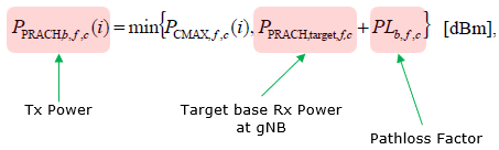
With one step deeper ino the equation, it simply says
i) Calculate P_PRACH,target,f,c + PL_b,f,c
ii) Compare the calculated power(P_PRACH,target,f,c + PL_b,f,c) with P_CMAX,f,c
iii) If the calculated power(P_PRACH,target,f,c + PL_b,f,c) is greater than P_CMAX,f,c, use P_CMAX,f,c. If the calculated poewr is lower than P_CMAX,f,c, then use the calculated power.
Sound simple ? Yes, it only SOUND Simple.. not really simple because the calculation of P_PRACH,target,f,c is pretty complicated as explained in this page and it involves many lower layer parameters which is not readily open to you.
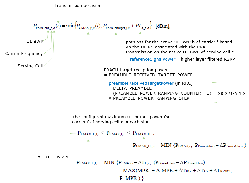

- P-EMAX,c : determined by p-Max in RRC message
- P_PowerClass : specified in the following table.
Power Class and Max Power
Power Class (P_PowerClass) and the Mas power allowed for the power class varies depending on Freuqency range (FR1 or FR2) and each specific band. Check out this note for the details.
Determination of referenceSignalPower
The description in this section is largely based on 38.213 - 7.4. As you might have guessed, ss-PBCH-BlockPower is fundamental reference signal for every cases. Only in some special cases CSI RS Power (PowerControlOffsetSS) is used.
- PRACH is not in response to a detection of a PDCCH order by the UE
- PRACH is in response to a detection of a PDCCH order by the UE that triggers a contention based random access procedure
- PRACH is associated with a link recovery procedure where a corresponding index q_new is associated with a SS/PBCH block
Then,
referenceSignalPower is determined by ss-PBCH-BlockPower
- PRACH is in response to a detection of a PDCCH order by the UE that triggers a noncontention based RACH procedure and depends the DL RS that the DM-RS of the PDCCH order is quasicollocated.
Then,
referenceSignalPower is determined by ss-PBCH-BlockPower
- PRACH is in response to a detection of a PDCCH order by the UE that triggers a noncontention based RACH procedure and the UE is configured resources for a periodic CSI-RS reception or the PRACH transmission is associated with a link recovery procedure where a corresponding index q_new is associated with a periodic CSI-RS configuration.
Then,
referenceSignalPower is determined by ss-PBCH-BlockPower and powerControlOffsetSS
, where powerControlOffsetSS (in RRC) is an offset of CSI-RS transmission power relative to SS/PBCH block transmission power.
if powerControlOffsetSS is not provided by RRC, UE assumes that this value is 0 dB
Determination of PREAMBLE_RECEIVED_TARGET_POWER
Three quantities are added to reach this value, and only the first is a plain configured number. The second depends on the preamble format, and the third grows every time an attempt goes unanswered. A UE on its fourth attempt is therefore transmitting well above the target the network configured.
PREAMBLE_RECEIVED_TARGET_POWER is determined by following equation (38.321 - 5.1.3)
PREAMBLE_RECEIVED_TARGET_POWER
= preambleReceivedTargetPower (in RRC)
+ DELTA_PREAMBLE
+ (PREAMBLE_POWER_RAMPING_COUNTER 1) PREAMBLE_POWER_RAMPING_STEP
- preambleReceivedTargetPower is a RRC parameter in RACH-ConfigGeneric,
- PREAMBLE_POWER_RAMPING_STEP is specified by the RRC Parameter powerRampingStep
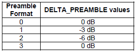
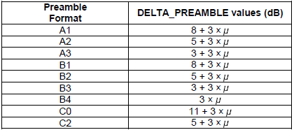
- DELTA_PREAMBLE is determined by pre-defined tables as shown below.
- PREAMBLE_POWER_RAMPING_COUNTER starts from 1 and gets incremented by 1 everytime PRACH is retransmited until it reaches the RRC parameter preambleTransMax.
< 38.321 V15.3.0 - Table 7.3-1: DELTA_PREAMBLE values for long preamble formats. >
< 38.321 V15.3.0 - Table 7.3-2: DELTA_PREAMBLE values for short preamble formats. >
Example of RRC Configuration :
The message below is a live SIB1 rather than an extract assembled for this page. Only a handful of its fields affect PRACH power, and the rest is kept so that their position among the other cell configuration stays visible.
This is an example of SIB1 configuration with IEs highlighted in red which are related te PRACH transmission power determination.
preambleReceivedTargetPower (-110) : This parameter is crucial in the context of 5G power control during the initial access process. It specifies the target power level for the PRACH. The UE adjusts its transmit power so that the preamble is received by the base station (gNodeB) above this target power level. This adjustment is essential for the UE to successfully initiate communication while managing power efficiently and minimizing interference.powerRampingStep (dB4) : This parameter is directly involved in the power control mechanism during the random access procedure. If the initial preamble transmission is not successful (i.e., the UE does not receive a response from the gNodeB), the UE will increase its transmit power for the next preamble attempt. The 'dB4' value indicates that the power ramping step size is 4 dB. Each subsequent preamble transmission will be increased by this step size until a response is received or a maximum number of attempts is reached.ss-PBCH-BlockPower (-36) : This is the power at which gNB transmit the reference signal (SSB block power). UE estimate PL (Path Loss) based on this power and the reference power that is measured by UE
Decoded RRC message,
{
message c1:systemInformationBlockType1 : {
cellSelectionInfo {
q-RxLevMin -70,
q-QualMin -20
},
cellAccessRelatedInfo {
...
},
connEstFailureControl {
...
},
servingCellConfigCommon {
downlinkConfigCommon {
frequencyInfoDL {
...
},
initialDownlinkBWP {
genericParameters {
...
},
pdcch-ConfigCommon setup: {
...
},
pdsch-ConfigCommon setup: {
...
}
},
bcch-Config {
...
},
pcch-Config {
...
}
},
uplinkConfigCommon {
frequencyInfoUL {
...
},
initialUplinkBWP {
genericParameters {
...
},
rach-ConfigCommon setup: {
rach-ConfigGeneric {
prach-ConfigurationIndex 160,
msg1-FDM one,
msg1-FrequencyStart 3,
zeroCorrelationZoneConfig 15,
preambleReceivedTargetPower -110,
preambleTransMax n7,
powerRampingStep dB4,
ra-ResponseWindow sl20
},
ssb-perRACH-OccasionAndCB-PreamblesPerSSB one: n8,
ra-ContentionResolutionTimer sf64,
prach-RootSequenceIndex l139: 1,
msg1-SubcarrierSpacing kHz30,
restrictedSetConfig unrestrictedSet
},
pusch-ConfigCommon setup: {
pusch-TimeDomainAllocationList {
{
k2 7,
mappingType typeA,
startSymbolAndLength 27
},
{
k2 4,
mappingType typeA,
startSymbolAndLength 27
},
{
k2 5,
mappingType typeA,
startSymbolAndLength 27
}
},
p0-NominalWithGrant -84
},
pucch-ConfigCommon setup: {
pucch-ResourceCommon 11,
pucch-GroupHopping neither,
p0-nominal -90
}
},
timeAlignmentTimerCommon infinity
},
ssb-PositionsInBurst {
...
},
ssb-PeriodicityServingCell ms20,
tdd-UL-DL-ConfigurationCommon {
...
},
ss-PBCH-BlockPower -36
},
ue-TimersAndConstants {
...
}
}
}
How msg3 Power is determined ?
msg3 Power is determined by following equation. As shown here, msg3 Power is based on msg1 Power(PRACH Power) with some offset values on top of it. It implies that msg3 power is also controlled by Open Loop Power Control mechanism like msg1(PRACH). This is based on 38.213-7.1.1
msg3 Power = preambleReceivedTargetPower + (2 x msg3-DeltaPreamble)
Two things are worth adding to that equation, because both are easy to miss. The first is where the offset comes from. 38.213 clause 7.1.1 takes it from msg3-DeltaPreamble or from deltaPreamble, and sets it to 0 dB when neither is provided, so a cell that configures nothing still has a defined msg3 power.
The second is that msg3 is not purely open loop after all. The RAR carries an uplink grant, and that grant includes a TPC field. 38.213 Table 8.2-2 turns that field into a power step, which then feeds the PUSCH power of clause 7.1.1. The network can therefore move the first scheduled transmission up or down before any other loop exists.
What follows the first transmission is different again. A msg3 retransmission is scheduled by DCI format 0_0 with the CRC scrambled by TC-RNTI, which puts it back on the ordinary PUSCH equation rather than this one. The page covers that case under Special Consideration for Msg3 PUSCH.
Two neighbouring parameters are worth knowing about while reading this. Release 16 added msgA-DeltaPreamble-r16 in MsgA-PUSCH-Config-r16 for the two step random access equivalent, and Release 17 added deltaPreamble-r17 inside FeatureCombinationPreambles-r17. Both carry the same INTEGER (-1..6) range as msg3-DeltaPreamble.
The offset has a defined default : 0 dB when neither msg3-DeltaPreamble nor deltaPreamble is provided.The RAR grant carries a TPC field : msg3 power is therefore not decided entirely before the RAR arrives.A retransmission leaves this equation : it is scheduled by DCI 0_0 with a TC-RNTI CRC and follows the PUSCH formula.The starting point is the preamble target, not the preamble power : preambleReceivedTargetPower is a receiver side figure, so the pathloss term is already accounted for.Two step RACH has its own field : msgA-DeltaPreamble-r16 plays the same role for msgA.
The grant itself has a clause of its own. 38.213 clause 8.3 covers PUSCH scheduled by a RAR uplink grant, and clause 7.1.1 then treats that case specially. A PUSCH transmission corresponding to a RAR uplink grant does not use P0-PUSCH-AlphaSet in the ordinary way, and the SRI based selection is bypassed because the grant carries no SRI field.
That exception is what makes msg3 worth its own section rather than a footnote to the PUSCH one. The equation on this page is the whole of it. None of the alpha sets, pathloss reference lists or closed loop indices described later are in play yet, because none of them has been configured.
The RAR grant is covered by clause 8.3 : it is not an ordinary DCI scheduled PUSCH, and clause 7.1.1 names it as an exception.No SRI field means no SRI selection : the pathloss reference and alpha set cannot be chosen per transmission at this point.Nothing dedicated has been configured yet : every parameter msg3 uses arrives in system information.
Example of RRC Configuration :
Only one field in the whole of SIB1 sets this offset, and it sits inside the common PUSCH configuration rather than anywhere RACH related. That placement is worth noting, because msg3 is a PUSCH transmission scheduled by the RAR rather than part of the preamble.
Following is based on
PUSCH-ConfigCommon ::=              SEQUENCE {
    groupHoppingEnabledTransformPrecoding   ENUMERATED {enabled}                                                OPTIONAL,   -- Need R
    pusch-TimeDomainAllocationList          PUSCH-TimeDomainResourceAllocationList                              OPTIONAL,   -- Need R
    msg3-DeltaPreamble                      INTEGER (-1..6)                                                     OPTIONAL,   -- Need R
    p0-NominalWithGrant                     INTEGER (-202..24)                                                  OPTIONAL,   -- Need R
    ...
}
The two power fields in that definition do different jobs, and only one of them applies to msg3. The field msg3-DeltaPreamble is the offset in the equation above, and p0-NominalWithGrant is the cell wide target for scheduled PUSCH, which the UE starts using once it is past the random access procedure.
How PUSCH Power is determined ?
Before jumping to the details of PRACH power calculation, let's just take a big picture of the equation as explained previous section. Overall structure of the equation can be highlighted as follows and you should be able to get the high level understanding as below. If you have difficulties with interpretation of this, check out the explanation in previous section again.
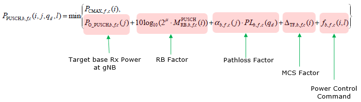
Detailed description on PUSCH power calculation is depicted as below. Some highlights are :
- Calculated TX power increases as Po_PUSCH power increases
- Calculated TX power increases as the scheduled number of RB increases
- Calculated TX power increases as the estimated pathloss increases and the impact of pathloss is affected by the scaling factor alpha
- Calculated TX power increases or decreases according to TPC command
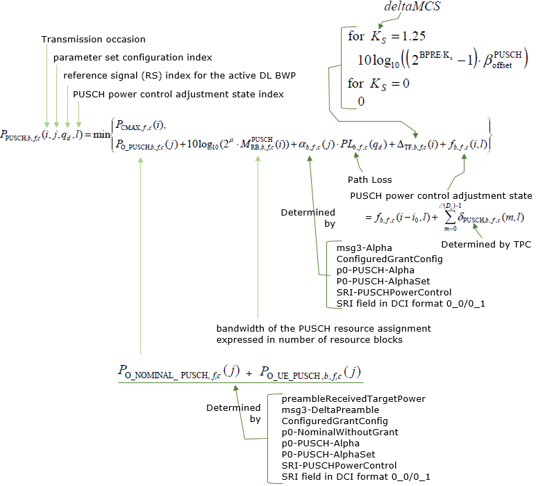
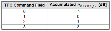
< 38.213 - Table 7.1.1-1: Mapping of TPC Command Field in a DCI format scheduling a PUSCH transmission, or in DCI format 2_2 with CRC scrambled by TPC-PUSCH-RNTI, or in DCI format 2_3, to absolute and accumulated δ_PUSCH,b,f,c values or δ_SRS,b,f,c values >

< 38.213 - Table 7.2.1-1: Mapping of TPC Command Field in a DCI format to accumulated δ_PUCCH,b,f,c values >
PO_PUSCH,b,f,c(j)
This is the target the gNB wants to receive, expressed at the receiver rather than at the transmitter. It splits into a cell wide part and a UE specific part, and the split is what lets the network move one UE without moving the whole cell.
The formula PO_PUSCH,b,f,c(j) represents the transmit power for a PUSCH transmission and is determined by the sum of two components:
PO_PUSCH,b,f,c(j) = PO_NOMINAL,PUSCH,f,c(j) + PO_UE_PUSCH,b,f,c(j)
, where
-
PO_NOMINAL,PUSCH,f,c(j):
- A nominal power offset value.
- Defined for carrier f of serving cell c.
- Can depend on higher-layer parameters, such as p0-NominalWithGrant or p0-NominalWithoutGrant, depending on whether it is a grant-free or grant-based configuration.
-
PO_UE_PUSCH,b,f,c(j):
- UE-specific power offset value for PUSCH transmission.
- Determined by higher-layer configurations, including parameters like p0-PUSCH-Alpha, p0-PUSCH-Alpha2, or related configurations in RRC signaling.
This value is further adjusted based on the transmission scenario, random access procedures, or specific grant types, as defined in 38.213 and 38.214.
p0-NominalWithGrant is a parameter used in the uplink power control mechanism in 5G to determine the baseline transmit power for PUSCH transmissions when the UE is scheduled via a grant (DCI format).
It essentially serves as a starting point or baseline power level that the UE uses to compute its PUSCH transmit power, considering additional factors such as pathloss, bandwidth,MCS, and dynamic power control commands.
-
p0−NominalWithGrant is the foundation of the transmit power calculation.
-
The gNB configures this value to ensure the UE's uplink signal is received at the target power level.
p0−PUSCH−Alpha and p0−PUSCH−Alpha2 are parameters used in the calculation of the uplink power control for Physical PUSCH transmissions. They allow the gNB to fine-tune how much the UE compensates for the pathloss when transmitting on the PUSCH.
-
Specifies a nominal transmit power baseline and a pathloss compensation factor (Alpha) for the PUSCH transmission.
-
It is used when the UE is scheduled by the gNB depending on the number of SRS resource set.
|
Parameter |
Usage |
Pathloss Reference |
Compensation Factor (α) |
|---|---|---|---|
|
p0-PUSCH-Alpha |
Single SRS resource set |
First SRS resource set |
Configured by p0-PUSCH-Alpha |
|
p0-PUSCH-Alpha2 |
Second SRS resource set (if provided) |
Second SRS resource set |
Configured by p0-PUSCH-Alpha2 |
10log10(2μ · MRB,b,f,cPUSCH(i))
This term adjusts the transmit power of the UE based on:
- Bandwidth size (RBs): Larger bandwidth (more RBs) requires more transmit power.
- SCS configuration: Higher SCS values correspond to larger resource block sizes(resource block size in terms of physical frequency bandwidth), requiring compensation in power calculation.
Followings are the breakdown of this term
-
2μ : μ is the subcarrier spacing (SCS) configuration, and 2μ accounts for the number of resource blocks (RBs) scaled based on the SCS value. For example:- μ = 0: SCS = 15 kHz → 20 = 1
- μ = 1: SCS = 30 kHz → 21 = 2
- μ = 2: SCS = 60 kHz → 22 = 4
- μ = 3: SCS = 120 kHz → 23 = 8
-
MPUSCHRB,b,f,c(i) : Represents the number of resource blocks (RBs) allocated for the PUSCH transmission in uplink bandwidth part b of carrier f, serving cell c, in the ith transmission occasion. This is determined by the scheduling grant from the gNB. -
10 log10 : Converts the product of 2μ · MPUSCHRB,b,f,c(i) into a logarithmic scale (dB). The result reflects the contribution of the bandwidth and resource allocation to the power calculation in decibels.
αb,f,c(j) PLb,f,c(qd)
This term combines the pathloss (PL) and compensation factor (a) to calculate the portion of pathloss included in the power control and it adjusts UE transmission power to ensure gNB receives the signal at the desired power level.
-
αb,f,c(j):
- Represents the pathloss compensation factor.
- A scaling parameter determining how much of the pathloss (PL) is compensated during power control.
- Value ranges between 0 and 1:
- α = 0: No pathloss compensation.
- α = 1: Full pathloss compensation.
- Varies based on the scheduling grant or power control command from the gNB.
-
PLb,f,c(qd):
- Represents the pathloss experienced in the communication link.
- Pathloss is the signal power attenuation as it propagates from transmitter to receiver, measured in dB.
- Components:
- b: Bandwidth part.
- f: Frequency.
- c: Serving cell.
- qd: Quantized delay or time instance for pathloss calculation.
ΔTF,b,f,c(i)
This term represents the transport format power offset in the context of uplink power control. This offset is applied to account for variations in power requirements due to different transport formats.
The factors affecting the transport format are
- Modulation and Coding Scheme (MCS) table.
- Number of resource blocks.
- Power control parameters.
fb,f,c(i,l)
Everything else in the PUSCH equation is open loop, computed by the UE from values it was configured with. This term is the only closed loop part, and it carries whatever the gNB has learned from actually receiving the UE.
This term represents the power adjustment by TPC (Transmit Power Control) command.
-
PUSCH Power Control Adjustment State (fb,f,c(i,l)):
- It is derived from:
- fb,f,c(i - i0, l): The adjustment state from the last transmission.
- ∑m=0|DL|-1 δPUSCH,b,f,c(m,l): The cumulative power control commands (δPUSCH) received via TPC (Transmit Power Control) for the current scheduling interval.
- It is derived from:
Adjustment by TPC:
- δPUSCH,b,f,c(m,l) indicates the transmit power control commands provided by the gNB to refine the UE's uplink transmission power.
Special Consideration for Msg3 PUSCH
msg3 is the first PUSCH after PRACH which does not have any previous PUSCH. So there is a little bit of aditional considerations in terms of estimating PUSCH transmission power.
The Msg3 PUSCH (the first PUSCH after PRACH, which does not have any previous PUSCH) has special considerations for PO_PUSCH,b,f,c(j):
- j = 0
- PO_UE_PUSCH,b,f,c(0) = 0
-
PO_NOMINAL,PUSCH,f,c(0) = PO_PRE + ΔPREAMBLE,Msg3, where:
- PO_PRE is provided by preambleReceivedTargetPower (as per TS 38.321).
- ΔPREAMBLE,Msg3 is provided by msg3-DeltaPreamble or deltaPreamble.
- If msg3-DeltaPreamble and deltaPreamble are not provided, ΔPREAMBLE,Msg3 = 0 dB.
- j = 0
- PO_UE_PUSCH,b,f,c(0) = 0
-
PO_NOMINAL,PUSCH,f,c(0) = PO_PRE + ΔMsgA_PUSCH, where:
- PO_PRE is provided by msgA-preambleReceivedTargetPower, or by preambleReceivedTargetPower if msgA-preambleReceivedTargetPower is not provided.
- ΔMsgA_PUSCH is provided by msgA-DeltaPreamble or deltaPreamble.
- If msgA-DeltaPreamble and deltaPreamble are not provided, ΔMsgA_PUSCH = ΔPREAMBLE,Msg3.
Example of RRC Configuration :
Two messages are needed here rather than one. SIB1 carries the cell wide part of the target power, and the RRC Setup carries the UE specific part, so neither message on its own accounts for the power a UE ends up using.
This is an example of SIB1 and RRC Setup configuration with IEs highlighted in red which are related te PUSCH transmission power determination.
p0-NominalWithGrant (-84) : This parameter is a key component in the formula used for calculating the uplink transmission power on the PUSCH. It serves as a baseline or reference power level from which adjustments are made based on various factors like path loss, UE power capability, and additional power control commands from the network.ss-PBCH-BlockPower (-36) : This is the power at which gNB transmit the reference signal (SSB block power). UE estimate PL (Path Loss) based on this power and the reference power that is measured by UEp0-AlphaSets : This section likely contains a set of alpha values and corresponding p0 values.- The alpha value is used to scale the effect of path loss in the power control formula, influencing how much the UE's transmission power should increase or decrease with varying path loss.
- Different sets of alpha and p0 values allow for different power control strategies under various network conditions or for different types of UEs.
pathlossReferenceRSToAddModList : This refers to a list of reference signal measurements used to calculate the path loss.- Each entry in the list (like "pusch-PathlossReferenceRS-Id 0") corresponds to a specific reference signal used for measuring path loss. The network can use these measurements to more accurately determine the current radio conditions experienced by the UE.
sri-PUSCH-MappingToAddModList : A list of SRI-PUSCH-PowerControl elements among which one is selected by the SRI field in DCI
Decoded RRC message,
{
message c1:systemInformationBlockType1 : {
cellSelectionInfo {
q-RxLevMin -70,
q-QualMin -20
},
cellAccessRelatedInfo {
...
},
connEstFailureControl {
...
},
servingCellConfigCommon {
downlinkConfigCommon {
frequencyInfoDL {
...
},
initialDownlinkBWP {
genericParameters {
...
},
pdcch-ConfigCommon setup: {
...
},
pdsch-ConfigCommon setup: {
...
}
},
bcch-Config {
...
},
pcch-Config {
...
}
},
uplinkConfigCommon {
frequencyInfoUL {
...
},
initialUplinkBWP {
genericParameters {
...
},
rach-ConfigCommon setup: {
rach-ConfigGeneric {
prach-ConfigurationIndex 160,
msg1-FDM one,
msg1-FrequencyStart 3,
zeroCorrelationZoneConfig 15,
preambleReceivedTargetPower -110,
preambleTransMax n7,
powerRampingStep dB4,
ra-ResponseWindow sl20
},
ssb-perRACH-OccasionAndCB-PreamblesPerSSB one: n8,
ra-ContentionResolutionTimer sf64,
prach-RootSequenceIndex l139: 1,
msg1-SubcarrierSpacing kHz30,
restrictedSetConfig unrestrictedSet
},
pusch-ConfigCommon setup: {
pusch-TimeDomainAllocationList {
{
k2 7,
mappingType typeA,
startSymbolAndLength 27
},
{
k2 4,
mappingType typeA,
startSymbolAndLength 27
},
{
k2 5,
mappingType typeA,
startSymbolAndLength 27
}
},
p0-NominalWithGrant -84
},
pucch-ConfigCommon setup: {
pucch-ResourceCommon 11,
pucch-GroupHopping neither,
p0-nominal -90
}
},
timeAlignmentTimerCommon infinity
},
ssb-PositionsInBurst {
...
},
ssb-PeriodicityServingCell ms20,
tdd-UL-DL-ConfigurationCommon {
...
},
ss-PBCH-BlockPower -36
},
ue-TimersAndConstants {
...
}
}
}
Decoded RRC message,
{
message c1: rrcSetup: {
rrc-TransactionIdentifier 0,
criticalExtensionsrrcSetup : {
radioBearerConfig {
..
},
masterCellGroup {
...
},
mac-CellGroupConfig {
...
},
physicalCellGroupConfig {
..
},
spCellConfig {
spCellConfigDedicated {
initialDownlinkBWP {
pdcch-Config setup: {
...
},
pdsch-Config setup: {
...
}
},
firstActiveDownlinkBWP-Id 0,
uplinkConfig {
...
},
pusch-Config setup: {
...
pusch-PowerControl {
msg3-Alpha alpha1,
p0-NominalWithoutGrant -84,
p0-AlphaSets {
{
p0-PUSCH-AlphaSetId 0,
p0 0,
alpha alpha1
}
},
pathlossReferenceRSToAddModList {
{
pusch-PathlossReferenceRS-Id 0,
referenceSignal ssb-Index: 0
}
},
sri-PUSCH-MappingToAddModList {
{
sri-PUSCH-PowerControlId 0,
sri-PUSCH-PathlossReferenceRS-Id 0,
sri-P0-PUSCH-AlphaSetId 0,
sri-PUSCH-ClosedLoopIndex i0
}
}
},
...
uci-OnPUSCH setup: {
betaOffsets semiStatic: {
betaOffsetACK-Index1 9,
betaOffsetACK-Index2 9,
betaOffsetACK-Index3 9,
betaOffsetCSI-Part1-Index1 7,
betaOffsetCSI-Part1-Index2 7,
betaOffsetCSI-Part2-Index1 7,
betaOffsetCSI-Part2-Index2 7
},
scaling f1
}
},
...
},
firstActiveUplinkBWP-Id 0,
pusch-ServingCellConfig setup: {
}
},
pdcch-ServingCellConfig setup: {
},
pdsch-ServingCellConfig setup: {
nrofHARQ-ProcessesForPDSCH n16
},
...
}
}
},
tag-Id 0
}
}
}
}
}
}
How PUCCH Power is determined ?
Before jumping into every details of PUCCH power calculation, let's first look at the overall structure of the equation. The structure is very similar to PUSCH power control, but there are a few important differences. PUCCH does not have the pathloss compensation factor alpha in the equation and it has PUCCH-format dependent offsets and UCI-payload dependent transport format offset.
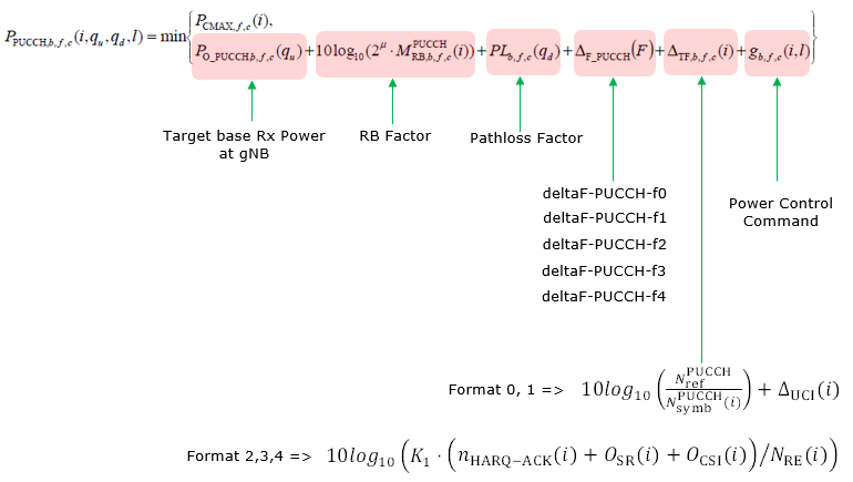
PUCCH transmission power is determined by following equation based on 38.213 clause 7.2.1.
PPUCCH,b,f,c(i,qu,qd,l) = min { PCMAX,f,c(i), PO_PUCCH,b,f,c(qu) + 10log10(2μ · MRB,b,f,cPUCCH(i)) + PLb,f,c(qd) + ΔF_PUCCH(F) + ΔTF,b,f,c(i) + gb,f,c(i,l) }
Some highlights are :
- Calculated TX power is capped by UE maximum configured output power PCMAX,f,c(i).
- Calculated TX power increases as PO_PUCCH increases.
- Calculated TX power increases as the number of RBs assigned to PUCCH increases.
- Calculated TX power increases as the estimated downlink pathloss increases.
- Different PUCCH formats can have different power offsets by deltaF-PUCCH-f0 through deltaF-PUCCH-f4.
- Calculated TX power can increase according to the amount of UCI bits carried by the PUCCH.
- Calculated TX power increases or decreases according to TPC command.
< 38.213 - Table 7.2.1-1: Mapping of TPC Command Field in a DCI format to accumulated δPUCCH,b,f,c values >
PO_PUCCH,b,f,c(qu)
PO_PUCCH,b,f,c(qu) is the target base receive power for PUCCH at gNB side. It is composed of a cell/common nominal part and an optional UE-specific part.
PO_PUCCH,b,f,c(qu) = PO_NOMINAL,PUCCH + PO_UE_PUCCH(qu)
- PO_NOMINAL,PUCCH is provided by p0-nominal in PUCCH-ConfigCommon. If p0-nominal is not provided, the value is 0 dBm.
- PO_UE_PUCCH(qu) is selected from P0-PUCCH values configured in p0-Set. Each entry has p0-PUCCH-Id and p0-PUCCH-Value.
- If PUCCH-SpatialRelationInfo is configured and activated, the UE uses the p0-PUCCH-Id associated with the activated spatial relation.
- If the UE does not get a UE-specific mapping, the UE uses the minimum p0-PUCCH-Id value in p0-Set.
p0-nominal is the common PUCCH power baseline. In the example log, p0-nominal -90 means that the common nominal target component for PUCCH is -90 dBm before adding UE-specific P0, bandwidth factor, pathloss, format offset, UCI related offset and TPC command.
p0-Set is a list of UE-specific PUCCH P0 offsets. If the list is configured, each p0-PUCCH-Value can be selected by PUCCH-SpatialRelationInfo, which also provides the pathloss reference and closed loop index.
10log10(2μ · MRB,b,f,cPUCCH(i))
A wider transmission spreads the same power density over more subcarriers, so the total power has to rise with the allocation to keep the received density constant. This term is that correction, and it is the same shape as the one in the PUSCH equation.
This term adjusts the transmit power according to the PUCCH bandwidth.
- 2μ represents the SCS configuration. For example, μ = 0 for 15 kHz, μ = 1 for 30 kHz, μ = 2 for 60 kHz and μ = 3 for 120 kHz.
- MRB,b,f,cPUCCH(i) is the bandwidth of the PUCCH resource assignment expressed in number of RBs for the PUCCH transmission occasion.
- 10log10 converts the resource bandwidth factor into dB scale.
PLb,f,c(qd)
PLb,f,c(qd) is the downlink pathloss estimate calculated by the UE from a configured reference signal. Unlike PUSCH, there is no alpha scaling factor in the PUCCH equation, so the pathloss term is applied directly.
- The reference signal can be SSB or CSI-RS configured in PUCCH-PathlossReferenceRS.
- If PUCCH-SpatialRelationInfo is provided, it can map the active PUCCH spatial relation to a pucch-PathlossReferenceRS-Id.
- If dedicated PUCCH pathloss reference information is not provided, the UE follows the default reference signal rules defined in 38.213. In many initial configurations this effectively uses an SSB based estimate.
ΔF_PUCCH(F)
PUCCH formats differ in how many symbols and subcarriers they occupy, so they do not all need the same power to be received equally well. This offset is what carries that difference, and it is configured per format rather than derived.
ΔF_PUCCH(F) is a format dependent power offset. It is configured by following RRC parameters in PUCCH-PowerControl.
PUCCH Format |
RRC Parameter |
If Not Provided |
|---|---|---|
Format 0 |
deltaF-PUCCH-f0 |
0 dB |
Format 1 |
deltaF-PUCCH-f1 |
0 dB |
Format 2 |
deltaF-PUCCH-f2 |
0 dB |
Format 3 |
deltaF-PUCCH-f3 |
0 dB |
Format 4 |
deltaF-PUCCH-f4 |
0 dB |
ΔTF,b,f,c(i)
ΔTF,b,f,c(i) is the transport format power adjustment for PUCCH. This term is mainly determined by PUCCH format, number of symbols, number of resource elements and number of UCI bits.
- ΔTF,b,f,c(i) = 10log10(NrefPUCCH / NsymbPUCCH(i)) + ΔUCI(i)
- For format 0, NrefPUCCH = 2 and ΔUCI(i) = 0.
- For format 1, NrefPUCCH = Nsymbslot. If the PUCCH carries multicast HARQ-ACK according to the second HARQ-ACK reporting mode, ΔUCI(i) = 0; otherwise ΔUCI(i) = 10log10(OUCI(i)).
- When the number of UCI bits is 11 or smaller, ΔTF,b,f,c(i) = 10log10(K1 · (nHARQ-ACK(i) + OSR(i) + OCSI(i)) / NRE(i)), where K1 = 6.
- When the number of UCI bits is larger than 11, ΔTF,b,f,c(i) = 10log10(2BPRE(i) · K2 - 1), where K2 = 2.4.
- BPRE(i) = (OACK(i) + OSR(i) + OCSI(i) + OCRC(i)) / NRE(i).
- NRE(i) is the number of resource elements available for UCI on the scheduled PUCCH resource.
gb,f,c(i,l)
This is the PUCCH counterpart of the PUSCH adjustment state, and it accumulates separately. A UE therefore runs two closed loops at once, and a TPC command sent for one channel does not move the other.
This term represents the closed loop power adjustment state for PUCCH. It is controlled by TPC commands from gNB.
- The TPC command can be included in a DCI format associated with the PUCCH transmission.
- The TPC command can also be provided by DCI format 2_2 with CRC scrambled by TPC-PUCCH-RNTI.
- If twoPUCCH-PC-AdjustmentStates is not configured, the UE uses one adjustment state, l = 0.
- If two PUCCH adjustment states are configured, the closed loop index can be selected by PUCCH-SpatialRelationInfo or by the relevant activation command.
- The accumulated delta values follow 38.213 Table 7.2.1-1 shown above.
Example of RRC Configuration :
This is an example of SIB1 and RRC Setup configuration with IEs related to PUCCH transmission power determination. The common part shown here is from the provided gNB log C:\temp\LTM\gnb-ltm-default.log.log. The dedicated pucch-PowerControl example shows how optional UE-specific parameters would map to the equation.
p0-nominal (-90) : Common nominal PUCCH target power. It contributes to PO_PUCCH.ss-PBCH-BlockPower (-36) : SSB transmit power used by the UE when estimating pathloss from SSB.p0-Set : UE-specific PUCCH P0 values. The selected p0-PUCCH-Value is added to p0-nominal.pathlossReferenceRSs : List of reference signals used for PUCCH pathloss calculation.spatialRelationInfoToAddModList : Maps a PUCCH spatial relation to pathloss reference, P0 entry and closed loop index.deltaF-PUCCH-f0..f4 : Format dependent PUCCH power offsets.
Decoded RRC message,
{
message c1:systemInformationBlockType1 : {
servingCellConfigCommon {
uplinkConfigCommon {
initialUplinkBWP {
pucch-ConfigCommon setup: {
pucch-ResourceCommon 11,
pucch-GroupHopping neither,
p0-nominal -90
}
}
},
ss-PBCH-BlockPower -36
}
}
}
Decoded RRC message,
{
  message c1: rrcSetup: {
    criticalExtensions rrcSetup: {
      masterCellGroup {
        spCellConfig {
          spCellConfigDedicated {
            uplinkConfig {
              initialUplinkBWP {
                pucch-Config setup: {
                  spatialRelationInfoToAddModList {
                    {
                      pucch-SpatialRelationInfoId 1,
                      referenceSignal ssb-Index: 0,
                      pucch-PathlossReferenceRS-Id 0,
                      p0-PUCCH-Id 1,
                      closedLoopIndex i0
                    }
                  },
                  pucch-PowerControl {
                    deltaF-PUCCH-f0 0,
                    deltaF-PUCCH-f1 0,
                    p0-Set {
                      { p0-PUCCH-Id 1, p0-PUCCH-Value 0 }
                    },
                    pathlossReferenceRSs {
                      { pucch-PathlossReferenceRS-Id 0, referenceSignal ssb-Index: 0 }
                    }
                  }
                }
              }
            }
          }
        }
      }
    }
  }
}
Examples
The equations above are easier to trust once they are seen against a real log. What follows is a capture taken during an initial attach, with the physical layer and MAC lines kept alongside the RRC messages so that each configured value can be matched to the power actually transmitted.
Example 01 : Power Control during RACH Process
This example shows how power control related information appears during the initial RACH procedure and the first few scheduled UL/DL transmissions after RACH. The main reference is the UE-side trace log C:\temp\LTM\ue-export.log, because uplink power is estimated at the UE side and this log includes the UE-side transmit power field p. I intentionally include not only RRC messages but also PHY/MAC lines for PRACH, RAR, PDCCH, PDSCH, PUSCH and PUCCH because power control is affected by all of these layers.
The main points to watch are :
PRACH uses open loop power control. The UE chooses PRACH transmit power from the RACH configuration such as preambleReceivedTargetPower and powerRampingStep, plus the estimated pathloss.RAR provides a MAC-level UL grant for Msg3 and includes tpc_command. This directly affects the first PUSCH after PRACH.PDCCH carries DCI for DL assignment or UL grant. The DCI lines after RACH show tpc_command, pucch_rsc, harq_feedback_timing and k2, which affect PUCCH/PUSCH power and timing.PUSCH lines show the actual uplink scheduled transmission, including RB allocation and modulation/coding information.PUCCH lines show ACK/SR/CSI transmission resources selected by RRC/DCI.PHR reports the UE power headroom and configured maximum power information after the UE is connected.
In this example, the UE uses the measured downlink pathloss to estimate the uplink transmit power for PRACH, Msg3 PUSCH, PUCCH and the following PUSCH. The arithmetic below shows the 38.213-style formula first, then plugs in the measured values and shows the resulting transmit power as the p value in the corresponding PHY line. The measured pathloss is PL=82 dB, estimated from ss-PBCH-BlockPower=8 dBm and SS-RSRP=-74 dBm.
High Level Signaling Flow : Power Control during RACH Process
# |
Direction |
Protocol |
Message / Log |
Power Control Meaning |
Cell config |
RRC / Common |
RACH / PUSCH / PUCCH common parameters |
Defines PRACH target power, power ramping step, PUSCH nominal power and PUCCH nominal power. |
|
UE measurement |
PHY / SSB |
SS-RSRP measurement |
UE estimates pathloss from SIB1 ss-PBCH-BlockPower and measured SS-RSRP. |
|
UE -> gNB |
PHY / PRACH |
PRACH preamble |
Open-loop PRACH is estimated by the UE. With measured PL=82 dB, the transmit power is p=-28.00. |
|
gNB -> UE |
MAC / PHY DL |
RAR on PDCCH/PDSCH |
RAR contains TA, UL grant and tpc_command=3 for the Msg3 PUSCH. |
|
UE -> gNB |
PHY / MAC / RRC |
Msg3 PUSCH + RRCSetupRequest |
First PUSCH after PRACH; power is affected by RAR grant/TPC and Msg3 power-control rules. |
|
gNB -> UE |
RRC |
RRCSetup |
Configures PUCCH resources, scheduling request resources and PUSCH closed-loop reference parameters. |
|
gNB -> UE |
MAC / PDCCH / PDSCH |
Contention Resolution + DL grant |
DL DCI has tpc_command=1, pucch_rsc=0 and HARQ feedback timing, determining the following PUCCH ACK. |
|
UE -> gNB |
PHY / PUCCH |
PUCCH ACK/SR/CSI |
PUCCH resource and format come from RRC/DCI; the UE log shows which PUCCH resource is transmitted. |
|
UE -> gNB |
PHY / MAC / RRC |
RRCSetupComplete + PUSCH + PHR |
UL DCI has tpc_command=1. The scheduled PUSCH carries SRB1/MAC data and a PHR showing power headroom and Pcmax. |
Before PRACH, the UE reads SIB1 and gets common uplink and RACH power-control parameters. In this example, the most important values for the RACH procedure are p-Max 10, preambleReceivedTargetPower -110, powerRampingStep dB4, p0-NominalWithGrant -90, p0-nominal -90 and ss-PBCH-BlockPower 8.
- SSB reference power : ss-PBCH-BlockPower = 8 dBm. This is used with the UE measured SS-RSRP in the next step to estimate pathloss.
- Maximum UE power cap : PCMAX = p-Max = 10 dBm.
- First PRACH target : PPRACH,target = preambleReceivedTargetPower + (preamble counter - 1) × powerRampingStep = -110 + (1 - 1) × 4 = -110 dBm.
- PUSCH common baseline : PO_NOMINAL,PUSCH = -90 dBm.
- PUCCH common baseline : PO_NOMINAL,PUCCH = -90 dBm.
00:00:00.000 [RRC] DL - BCCH-DL-SCH-NR: systemInformationBlockType1
{
  message c1: systemInformationBlockType1: {
    ...
    servingCellConfigCommon {
      downlinkConfigCommon {
        ...
        initialDownlinkBWP {
          ...
          pdcch-ConfigCommon setup: {
            ...
            ra-SearchSpace 1
          },
          pdsch-ConfigCommon setup: { ... }
        }
      },
      uplinkConfigCommon {
        frequencyInfoUL {
          scs-SpecificCarrierList {
            { offsetToCarrier 0, subcarrierSpacing kHz30, carrierBandwidth 51 }
          },
          p-Max 10
        },
        initialUplinkBWP {
          genericParameters {
            locationAndBandwidth 13750,
            subcarrierSpacing kHz30
          },
          rach-ConfigCommon setup: {
            rach-ConfigGeneric {
              prach-ConfigurationIndex 160,
              msg1-FDM one,
              msg1-FrequencyStart 0,
              zeroCorrelationZoneConfig 15,
              preambleReceivedTargetPower -110,
              preambleTransMax n7,
              powerRampingStep dB4,
              ra-ResponseWindow sl20
            },
            ssb-perRACH-OccasionAndCB-PreamblesPerSSB one: n8,
            ra-ContentionResolutionTimer sf64,
            prach-RootSequenceIndex l139: 1,
            msg1-SubcarrierSpacing kHz30,
            restrictedSetConfig unrestrictedSet
          },
          pusch-ConfigCommon setup: {
            pusch-TimeDomainAllocationList {
              { k2 7, mappingType typeA, startSymbolAndLength 27 },
              { k2 4, mappingType typeA, startSymbolAndLength 27 },
              { k2 2, mappingType typeA, startSymbolAndLength 27 }
            },
            p0-NominalWithGrant -90
          },
          pucch-ConfigCommon setup: {
            pucch-ResourceCommon 11,
            pucch-GroupHopping neither,
            p0-nominal -90
          }
        },
        timeAlignmentTimerCommon infinity
      },
      ssb-PositionsInBurst {
        inOneGroup '80'H
      },
      ssb-PeriodicityServingCell ms20,
      tdd-UL-DL-ConfigurationCommon {
        referenceSubcarrierSpacing kHz30,
        pattern1 {
          dl-UL-TransmissionPeriodicity ms5,
          nrofDownlinkSlots 7,
          nrofDownlinkSymbols 6,
          nrofUplinkSlots 2,
          nrofUplinkSymbols 1
        }
      },
      ss-PBCH-BlockPower 8
    },
    ue-TimersAndConstants { ... }
  }
}
After reading the SSB/PBCH and SIB1, the UE can estimate downlink pathloss from the configured SSB transmit power and the measured SS-RSRP. In this example, assume the UE measures SS-RSRP=-74 dBm.
- Formula : PL = ss-PBCH-BlockPower - SS-RSRP.
- Plug in numbers : PL = 8 - (-74) = 82 dB.
- Pathloss used for the following steps : PL = 82 dB.
20:10:28.560 [PHY] DL 0001 00 - 94.00 SSB/PBCH measurement ss-PBCH-BlockPower=8 ss-rsrp=-74.0 PL=82.0
The PRACH line is the first visible UL transmission. PRACH transmit power is selected by open-loop control using the RACH target power and the measured pathloss.
- Formula : PPRACH = min(PCMAX, preambleReceivedTargetPower + PL + Δpreamble + ramping).
- Plug in numbers : PPRACH = min(10, -110 + PL + 0 + 0) = min(10, PL - 110) dBm.
- Use example pathloss : with PL=82 dB, PPRACH = min(10, 82 - 110).
- Formula estimate : PPRACH = -28.00 dBm.
20:10:28.578 [PHY] UL 0001 00 - 96.19 PRACH: sequence_index=2 prb=0:12 symb=2:12 epre=-5.2 p=-28.00
After detecting PRACH, the gNB sends Random Access Response. This is delivered on DL using PDCCH and PDSCH. The RAR carries ta=5, an ul_grant and tpc_command=3. This TPC command is important because it is applied to the Msg3 PUSCH power calculation.
- Formula : PMsg3 = min(PCMAX, PO_PRE + ΔPREAMBLE,Msg3 + 10log10(2μMRB) + αPL + ΔTF + f).
- RAR TPC : tpc_command=3 in the RAR UL grant maps to 0 dB for the Msg3 RAR TPC adjustment.
- RB factor : μ=1 for 30 kHz SCS and the RAR grant schedules one RB for Msg3, so 10log10(21×1) = 3.01 dB.
- Plug in numbers : PMsg3 = min(10, -110 + 0 + 3.01 + 1×82 + 0 + 0) = min(10, -24.99) dBm.
- Formula estimate : PMsg3 = -24.99 dBm.
- Estimated p field : the corresponding Msg3 PUSCH line in Step 4 is shown with p=-24.99, matching the formula estimate.
20:10:28.587 [PHY] DL 0001 00 010d   97.13 PDCCH: ss_id=1 cce_index=0 al=4 dci=1_0
        rb_alloc=0x2e
        time_domain_rsc=0
        vrb_to_prb_map=0
        mcs=2
        tb_scaling=0
20:10:28.588 [PHY] DL 0001 00 010d   97.13 PDSCH: harq=si prb=35:2 symb=1:13 CW0: tb_len=11 mod=2 rv_idx=0 cr=0.19 crc=OK snr=36.1 epre=-75.2
20:10:28.588 [MAC] DL    - 00 RAR: rapid=2
        rapid=2
          ta=5
          ul_grant:
            hopping_flag=0
            riv=0x30
            time_domain_rsc=2
            mcs=4
            tpc_command=3
            csi_request=0
          tc-rnti=0x4628
20:10:28.588 [MAC] -  0001 00 ta=5 ul_grant=0x30246 tc_rnti=0x4628
Msg3 is transmitted on PUSCH using the UL grant from RAR. In the UE log, Msg3 appears as a PUSCH with prb=48. This PUSCH carries the CCCH RRCSetupRequest.
- Formula : PMsg3 = min(PCMAX, PO_PRE + ΔPREAMBLE,Msg3 + 10log10(2μMRB) + αPL + ΔTF + f).
- Plug in numbers : PMsg3 = min(10, -110 + 0 + 3.01 + 82 + 0 + 0) = min(10, -24.99) dBm.
- Formula estimate : PMsg3 = -24.99 dBm.
- Estimated p field : the displayed Msg3 PUSCH line uses p=-24.99, matching the formula estimate.
20:10:28.572 [RRC] UL 0001 00 CCCH-NR: RRC setup request
        {
          message c1: rrcSetupRequest: {
            rrcSetupRequest {
              ue-Identity randomValue: '001101111110000011110111001011101110010'B,
              establishmentCause mo-Signalling,
              spare '0'B
            }
          }
        }
20:10:28.588 [MAC] UL 0001 00 LCID:52 len=6 PAD:len=1
        CCCH
20:10:28.588 [PHY] UL 0001 00 4628   97.18 PUSCH: harq=0 prb=48 symb=0:14 CW0: tb_len=9 mod=2 rv_idx=0 cr=0.30 retx=0 p=-24.99
The RRCSetup message configures the connected-mode UL resources. For power control, the important part is the combination of PUCCH resources, SR resource, PUSCH power control and pathloss reference. The PUSCH power-control block contains msg3-Alpha alpha1, p0 0, alpha alpha1, SSB-based pathloss reference and closed-loop index.
- Connected-mode PUSCH formula : PPUSCH = min(PCMAX, PO_PUSCH + 10log10(2μMRB) + αPL + ΔTF + f).
- PUSCH plug in numbers for a later 29-RB UL grant : PPUSCH = min(10, (-90+0) + 10log10(21×29) + 1×82 + 0 + f) = min(10, 9.63 + f) dBm.
- PUSCH final result with later DCI tpc_command=1 : tpc_command=1 maps to 0 dB accumulated adjustment, so f=0 and the formula estimate is PPUSCH = 9.63 dBm.
- PUCCH format 1 formula : PPUCCH = min(PCMAX, PO_PUCCH + 10log10(2μMRB) + PL + ΔF + ΔTF + g).
- PUCCH format 1 plug in numbers : PPUCCH,F1 = min(10, -90 + 10log10(21×1) + 82 + 0 + 0 + g) = min(10, -4.99 + g) dBm.
20:10:28.594 [RRC] DL 0001 00 CCCH-NR: RRC setup
{
  message c1: rrcSetup: {
    ...
    spCellConfig {
      spCellConfigDedicated {
        uplinkConfig {
          initialUplinkBWP {
            pucch-Config setup: {
              resourceSetToAddModList { ... },
              resourceToAddModList {
                { pucch-ResourceId 0, startingPRB 50, secondHopPRB 0, format format1: { nrofSymbols 14, ... } },
                ...
                { pucch-ResourceId 8, startingPRB 1, secondHopPRB 49, format format4: { nrofSymbols 14, ... } },
                ...
                { pucch-ResourceId 12, startingPRB 50, secondHopPRB 0, format format1: { initialCyclicShift 9, nrofSymbols 14, timeDomainOCC 2 } }
              },
              format1 setup: { },
              format4 setup: {
                maxCodeRate zeroDot25,
                simultaneousHARQ-ACK-CSI true
              },
              schedulingRequestResourceToAddModList {
                { schedulingRequestResourceId 1, schedulingRequestID 0, periodicityAndOffset sl40: 8, resource 12 }
              },
              dl-DataToUL-ACK { 8, 7, 6, 5, 4, 12, 11 }
            },
            pusch-Config setup: {
              ...
              pusch-PowerControl {
                msg3-Alpha alpha1,
                p0-AlphaSets {
                  { p0-PUSCH-AlphaSetId 0, p0 0, alpha alpha1 }
                },
                pathlossReferenceRSToAddModList {
                  { pusch-PathlossReferenceRS-Id 0, referenceSignal ssb-Index: 0 }
                },
                sri-PUSCH-MappingToAddModList {
                  { sri-PUSCH-PowerControlId 0, sri-PUSCH-PathlossReferenceRS-Id 0, sri-P0-PUSCH-AlphaSetId 0, sri-PUSCH-ClosedLoopIndex i0 }
                }
              }
            }
          }
        }
      }
    }
  }
}
The contention resolution MAC CE is followed by a DL PDCCH/PDSCH. The DCI includes tpc_command=1, pucch_rsc=0 and harq_feedback_timing=3. These determine the following HARQ-ACK PUCCH resource/timing and apply closed-loop PUCCH power control.
- TPC formula : g(i) = g(i-i0) + δPUCCH.
- Plug in numbers : tpc_command=1 maps to δPUCCH=0 dB, so g(i) = g(i-i0) + 0. For the first connected-mode PUCCH in this example, use g=0.
- Formula estimate : PPUCCH,F1 = min(10, -90 + 3.01 + 82 + 0 + 0 + 0) = -4.99 dBm.
- Estimated p field : the following HARQ-ACK PUCCH line is shown with p=-4.99, matching the formula estimate.
20:10:28.593 [PHY] DL 0001 00 4628    98.5 PDCCH: ss_id=1 cce_index=0 al=4 dci=1_0
        rb_alloc=0x2f
        time_domain_rsc=0
        mcs=6
        ndi=1
        rv_idx=0
        harq_process=0
        dai=0
        tpc_command=1
        pucch_rsc=0
        harq_feedback_timing=3
20:10:28.594 [PHY] DL 0001 00 4628    98.5 PDSCH: harq=0 prb=13:24 symb=1:13 k1=4 CW0: tb_len=317 mod=2 rv_idx=0 cr=0.44 retx=0 crc=OK snr=37.1 epre=-75.0
20:10:28.594 [PHY] UL 0001 00 0000    98.9 PUCCH: format=1 prb=0 prb2=50 symb=0:14 cs=0 occ=0 ack=1 p=-4.99
20:10:28.594 [MAC] DL 0001 00 UECRI:137e0f72ee46 LCID:0 len=301 PAD:len=5
        UE Contention Resolution Identity: 137e0f72ee46
After the DL assignment, UE transmits PUCCH for HARQ-ACK. Shortly after that, SR and CSI PUCCH transmissions also appear. These lines show the actual PUCCH format, PRB/frequency hopping information and the estimated transmit power.
- ACK/SR PUCCH format 1 formula : PPUCCH,F1 = min(PCMAX, PO_PUCCH + 10log10(2μMRB) + PL + ΔF1 + ΔTF + g).
- ACK/SR plug in numbers : PPUCCH,F1 = min(10, -90 + 3.01 + 82 + 0 + 0 + 0) = -4.99 dBm.
- CSI PUCCH format 4 formula : PPUCCH,F4 = min(10, -90 + 3.01 + PL + 0 + ΔTF,CSI + 0).
- CSI transport factor : for csi=1001111, OCSI=7 bits and OUCI≤11, so ΔTF,CSI = 10log10(6×7/NRE) = 10log10(42/NRE).
- CSI formula estimate : PPUCCH,F4 = min(10, -4.99 + 10log10(42/NRE)) dBm. If only the log-visible 1 RB × 14 symbols upper-bound is used, NRE≈168 and PPUCCH,F4≈-11.01 dBm.
- Estimated p field : the ACK, SR and CSI PUCCH lines below are shown with formula-derived p values.
20:10:28.594 [PHY] UL 0001 00 0000    98.9 PUCCH: format=1 prb=0 prb2=50 symb=0:14 cs=0 occ=0 ack=1 p=-4.99
20:10:28.613 [PHY] UL 0001 00 4628   100.8 PUCCH: format=1 prb=50 prb2=0 symb=0:14 cs=9 occ=2 sr=1 p=-4.99
20:10:28.613 [PHY] UL 0001 00 4628   100.9 PUCCH: format=4 prb=49 prb2=1 symb=0:14 occ=0 csi=1001111 p=-11.01
20:10:28.649 [PHY] UL 0001 00 4628  103.19 PUCCH: format=1 prb=50 prb2=0 symb=0:14 cs=1 occ=0 ack=1 p=-4.99
The next UL grant is carried by DCI 0_1 on PDCCH. It includes tpc_command=1 and k2=4. The scheduled PUSCH carries MAC control elements including BSR and PHR. The PHR line gives direct visibility into UE power status: PH: 38 (63) and Pcmax: 40. The RRCSetupComplete message is generated immediately before this UL grant and is then carried through SRB1/RLC/PDCP/MAC.
- Formula : PPUSCH = min(PCMAX, PO_PUSCH + 10log10(2μMRB) + αPL + ΔTF + f).
- Plug in numbers : MRB=29, μ=1, PO_PUSCH=-90, α=1, PL=82, ΔTF=0 and tpc_command=1 gives f=0. Therefore PPUSCH = min(10, -90 + 10log10(21×29) + 82 + 0 + 0) = min(10, 9.63) dBm.
- Formula estimate : PPUSCH = 9.63 dBm.
- Estimated p field : the displayed PUSCH line uses p=9.63, matching the formula estimate.
- PHR cross-check : the MAC CE reports PH: 38 (63) and Pcmax: 40. This reports the UE power-headroom state and configured maximum power information.
20:10:28.594 [RRC] UL 0001 00 DCCH-NR: RRC setup complete
20:10:28.618 [PHY] DL 0001 00 4628  100.15 PDCCH: ss_id=2 cce_index=6 al=2 dci=0_1 k2=4
        rb_alloc=0x4b3
        time_domain_rsc=1
        mcs=0
        ndi=1
        rv_idx=0
        harq_process=0
        dai=3
        tpc_command=1
        antenna_ports=0
        srs_request=0
        dmrs_seq_init=0
        ul_sch_indicator=1
20:10:28.618 [PDCP] UL 0001 SRB1 SN=0
20:10:28.618 [RLC] UL 0001 SRB1 D/C=1 P=1 SI=00 SN=0
20:10:28.618 [MAC] UL 0001 00 LCID:1 len=36 SBSR:lcg=0 bs=0 SE PHR:ph=63 pc=40 PAD:len=89
        Short BSR:
          LCG ID: 0 Buffer Size: 0 (0)
        Single Entry PHR:
          P: 0 PH: 38 (63)
          MPE or DPC or R: 0 Pcmax: 40
20:10:28.618 [PHY] UL 0001 00 4628  100.19 PUSCH: harq=0 prb=20:29 symb=0:14 CW0: tb_len=133 mod=2 rv_idx=0 cr=0.12 retx=0 p=9.63
RRC Parameters involved in Power Control
The definitions below are collected here rather than repeated in each section, because most of them feed more than one equation. Reading them together also shows how few of the fields are mandatory, and how much of a power configuration is therefore left at its default.
The first group holds the cell level values. Every one of them reaches the UE in system information, so they are in place before the UE has transmitted anything, which is what makes the PRACH calculation possible at all.
Following is based on
FrequencyInfoUL-SIB ::=             SEQUENCE {
    frequencyBandList                   MultiFrequencyBandListNR-SIB                            OPTIONAL,   -- Cond FDD-OrSUL
    absoluteFrequencyPointA             ARFCN-ValueNR                                           OPTIONAL,   -- Cond FDD-OrSUL
    scs-SpecificCarrierList             SEQUENCE (SIZE (1..maxSCSs)) OF SCS-SpecificCarrier,
    p-Max                               P-Max                                                   OPTIONAL,   -- Need S
    frequencyShift7p5khz                ENUMERATED {true}                                       OPTIONAL,   -- Cond FDD-TDD-OrSUL-Optional
    ...,
    [[
    frequencyBandListAerial-r18         MultiFrequencyBandListNR-Aerial-SIB-r18                 OPTIONAL    -- Need S
    ]]
}

ServingCellConfigCommonSIB ::=      SEQUENCE {
    ...                                                                                                     -- downlinkConfigCommon through tdd-UL-DL-ConfigurationCommon are not power related
    ss-PBCH-BlockPower                  INTEGER (-60..50),
    ...,
    -- the r16, r17 and v1760 extension groups follow here, and none of them is power related
}

RACH-ConfigGeneric ::=              SEQUENCE {
    prach-ConfigurationIndex            INTEGER (0..255),
    msg1-FDM                            ENUMERATED {one, two, four, eight},
    msg1-FrequencyStart                 INTEGER (0..maxNrofPhysicalResourceBlocks-1),
    zeroCorrelationZoneConfig           INTEGER(0..15),
    preambleReceivedTargetPower         INTEGER (-202..-60),
    preambleTransMax                    ENUMERATED {n3, n4, n5, n6, n7, n8, n10, n20, n50, n100, n200},
    powerRampingStep                    ENUMERATED {dB0, dB2, dB4, dB6},
    ra-ResponseWindow                   ENUMERATED {sl1, sl2, sl4, sl8, sl10, sl20, sl40, sl80},
    ...,
    [[
    ...                                                                                                     -- the IAB and ra-ResponseWindow r16 fields
    ]],
    [[
    ra-ResponseWindow-v1700                     ENUMERATED {sl240, sl320, sl640, sl960, sl1280, sl1920, sl2560} OPTIONAL    -- Need R
    ]],
    [[
    sbfd-RACH-SingleConfig-preambleReceivedTargetPower-r19     INTEGER (-202..-60)                              OPTIONAL    -- Need R
    ]]
}

NZP-CSI-RS-Resource ::=             SEQUENCE {
    nzp-CSI-RS-ResourceId               NZP-CSI-RS-ResourceId,
    resourceMapping                     CSI-RS-ResourceMapping,
    powerControlOffset                  INTEGER (-8..15),
    powerControlOffsetSS                ENUMERATED{db-3, db0, db3, db6}                 OPTIONAL,   -- Need R
    ...                                                                                             -- scramblingID onward, and the r18 and r19 groups, are not power related
}
Two changes since the version this page was written against are worth noting. RACH-ConfigGeneric gained a Release 19 extension group carrying
preambleReceivedTargetPower is the only mandatory power field here : it sits in RACH-ConfigGeneric with a range of -202 to -60 dBm and no OPTIONAL marker.powerRampingStep has four values : dB0, dB2, dB4 and dB6, so a cell can disable ramping entirely by configuring dB0.preambleTransMax bounds the ramp : the counter in the target power equation cannot exceed this, which caps how far above the configured target a UE can climb.ss-PBCH-BlockPower is the referenceSignalPower : it is the transmitted power the UE subtracts its measured RSRP from to estimate pathloss.p-Max is separate from the power class : the cell can lower the ceiling below what the UE is capable of, and the lower of the two applies.
The second group is everything the PUSCH equation reads. Almost all of it arrives in dedicated signalling rather than system information, which is why a UE uses a different target once it has an RRC connection than it used for msg3.
Following is based on
PUSCH-ConfigCommon ::=              SEQUENCE {
    groupHoppingEnabledTransformPrecoding   ENUMERATED {enabled}                                                OPTIONAL,   -- Need R
    pusch-TimeDomainAllocationList          PUSCH-TimeDomainResourceAllocationList                              OPTIONAL,   -- Need R
    msg3-DeltaPreamble                      INTEGER (-1..6)                                                     OPTIONAL,   -- Need R
    p0-NominalWithGrant                     INTEGER (-202..24)                                                  OPTIONAL,   -- Need R
    ...
}

PUSCH-Config ::=                        SEQUENCE {
    ...                                                                                                     -- dataScramblingIdentityPUSCH through frequencyHopping are not power related
    pusch-PowerControl                      PUSCH-PowerControl                                              OPTIONAL,   -- Need M
    ...                                                                                                     -- the rest of the base members, and the r16 to r19 groups
}

PUSCH-PowerControl ::=              SEQUENCE {
    tpc-Accumulation                    ENUMERATED { disabled }                                                 OPTIONAL, -- Need S
    msg3-Alpha                          Alpha                                                                   OPTIONAL, -- Need S
    p0-NominalWithoutGrant              INTEGER (-202..24)                                                      OPTIONAL, -- Need M
    p0-AlphaSets                        SEQUENCE (SIZE (1..maxNrofP0-PUSCH-AlphaSets)) OF P0-PUSCH-AlphaSet     OPTIONAL, -- Need M
    pathlossReferenceRSToAddModList     SEQUENCE (SIZE (1..maxNrofPUSCH-PathlossReferenceRSs)) OF PUSCH-PathlossReferenceRS
                                                                                                                OPTIONAL, -- Need N
    pathlossReferenceRSToReleaseList    SEQUENCE (SIZE (1..maxNrofPUSCH-PathlossReferenceRSs)) OF PUSCH-PathlossReferenceRS-Id
                                                                                                                OPTIONAL,  -- Need N
    twoPUSCH-PC-AdjustmentStates        ENUMERATED {twoStates}                                                  OPTIONAL, -- Need S
    deltaMCS                            ENUMERATED {enabled}                                                    OPTIONAL, -- Need S
    sri-PUSCH-MappingToAddModList       SEQUENCE (SIZE (1..maxNrofSRI-PUSCH-Mappings)) OF SRI-PUSCH-PowerControl
                                                                                                                OPTIONAL, -- Need N
    sri-PUSCH-MappingToReleaseList      SEQUENCE (SIZE (1..maxNrofSRI-PUSCH-Mappings)) OF SRI-PUSCH-PowerControlId
                                                                                                                OPTIONAL  -- Need N
}

P0-PUSCH-AlphaSet ::=               SEQUENCE {
    p0-PUSCH-AlphaSetId                 P0-PUSCH-AlphaSetId,
    p0                                  INTEGER (-16..15)                                                       OPTIONAL, -- Need S
    alpha                               Alpha                                                                   OPTIONAL  -- Need S
}

Alpha ::=                           ENUMERATED {alpha0, alpha04, alpha05, alpha06, alpha07, alpha08, alpha09, alpha1}

P0-PUSCH-AlphaSetId ::=             INTEGER (0..maxNrofP0-PUSCH-AlphaSets-1)

PUSCH-PathlossReferenceRS ::=       SEQUENCE {
    pusch-PathlossReferenceRS-Id        PUSCH-PathlossReferenceRS-Id,
    referenceSignal                     CHOICE {
        ssb-Index                           SSB-Index,
        csi-RS-Index                        NZP-CSI-RS-ResourceId
    }
}

PUSCH-PathlossReferenceRS-Id ::=    INTEGER (0..maxNrofPUSCH-PathlossReferenceRSs-1)

SRI-PUSCH-PowerControl ::=          SEQUENCE {
    sri-PUSCH-PowerControlId            SRI-PUSCH-PowerControlId,
    sri-PUSCH-PathlossReferenceRS-Id    PUSCH-PathlossReferenceRS-Id,
    sri-P0-PUSCH-AlphaSetId             P0-PUSCH-AlphaSetId,
    sri-PUSCH-ClosedLoopIndex           ENUMERATED { i0, i1 }
}

SRI-PUSCH-PowerControlId ::=        INTEGER (0..maxNrofSRI-PUSCH-Mappings-1)

BetaOffsets ::=                     SEQUENCE {
    betaOffsetACK-Index1                INTEGER(0..31)                                                          OPTIONAL, -- Need S
    betaOffsetACK-Index2                INTEGER(0..31)                                                          OPTIONAL, -- Need S
    betaOffsetACK-Index3                INTEGER(0..31)                                                          OPTIONAL, -- Need S
    betaOffsetCSI-Part1-Index1          INTEGER(0..31)                                                          OPTIONAL, -- Need S
    betaOffsetCSI-Part1-Index2          INTEGER(0..31)                                                          OPTIONAL, -- Need S
    betaOffsetCSI-Part2-Index1          INTEGER(0..31)                                                          OPTIONAL, -- Need S
    betaOffsetCSI-Part2-Index2          INTEGER(0..31)                                                          OPTIONAL  -- Need S
}
Three of these deserve a second look. Setting
The target splits across two messages : p0-NominalWithGrant is in PUSCH-ConfigCommon and the per UE part is in P0-PUSCH-AlphaSet.alpha and p0 travel as a pair : a P0-PUSCH-AlphaSet carries both, so selecting a set changes the pathloss weighting and the target together.The pathloss reference can be an SSB or a CSI-RS : PUSCH-PathlossReferenceRS is a CHOICE between the two.SRI-PUSCH-PowerControl ties three choices to one DCI field : the SRI selects a pathloss reference, an alpha set and a closed loop index at once.msg3-Alpha is separate from the connected mode alpha : it sits directly in PUSCH-PowerControl rather than inside an alpha set.
The third group is the PUCCH equivalent. It repeats the same shape, with a target, a pathloss reference and a closed loop, and it adds the per format offset that PUSCH has no need for.
Following is based on
PUCCH-Config ::=                        SEQUENCE {
    ...                                                                                                     -- the resource and format lists are not power related
    pucch-PowerControl                      PUCCH-PowerControl                                              OPTIONAL,   -- Need M
    ...                                                                                                     -- the remaining base members and the r16 to r19 groups
}

PUCCH-PowerControl ::=              SEQUENCE {
    deltaF-PUCCH-f0                     INTEGER (-16..15)                                                       OPTIONAL, -- Need R
    deltaF-PUCCH-f1                     INTEGER (-16..15)                                                       OPTIONAL, -- Need R
    deltaF-PUCCH-f2                     INTEGER (-16..15)                                                       OPTIONAL, -- Need R
    deltaF-PUCCH-f3                     INTEGER (-16..15)                                                       OPTIONAL, -- Need R
    deltaF-PUCCH-f4                     INTEGER (-16..15)                                                       OPTIONAL, -- Need R
    p0-Set                              SEQUENCE (SIZE (1..maxNrofPUCCH-P0-PerSet)) OF P0-PUCCH                 OPTIONAL, -- Need M
    pathlossReferenceRSs                SEQUENCE (SIZE (1..maxNrofPUCCH-PathlossReferenceRSs)) OF PUCCH-PathlossReferenceRS
                                                                                                                OPTIONAL, -- Need M
    twoPUCCH-PC-AdjustmentStates        ENUMERATED {twoStates}                                                  OPTIONAL, -- Need S
    ...,
    [[
    pathlossReferenceRSs-v1610          SetupRelease { PathlossReferenceRSs-v1610 }                             OPTIONAL -- Need M
    ]]
}

P0-PUCCH ::=                            SEQUENCE {
    p0-PUCCH-Id                             P0-PUCCH-Id,
    p0-PUCCH-Value                          INTEGER (-16..15)
}

P0-PUCCH-Id ::=                         INTEGER (1..8)

PUCCH-PathlossReferenceRS ::=                   SEQUENCE {
    pucch-PathlossReferenceRS-Id                PUCCH-PathlossReferenceRS-Id,
    referenceSignal                             CHOICE {
        ssb-Index                                   SSB-Index,
        csi-RS-Index                                NZP-CSI-RS-ResourceId
    }
}
The two power controls are deliberately parallel, and the differences are the interesting part. PUCCH has five per format offsets where PUSCH has none, and PUSCH has a modulation dependent term and an SRI mapping where PUCCH has neither. Both offer two adjustment states, and both choose their pathloss reference between an SSB and a CSI-RS.
deltaF-PUCCH-f0 to f4 have no PUSCH counterpart : PUCCH formats differ in structure, and PUSCH does not.P0-PUCCH-Id starts at 1 : it runs 1 to 8, unlike the PUSCH alpha set identity which starts at 0.The PUCCH target has no alpha of its own : the PUCCH equation applies the full pathloss, so there is no fractional weighting to configure.Release 16 added a second pathloss list : pathlossReferenceRSs-v1610 is a SetupRelease, so it can be released independently.Both loops can be doubled : twoPUCCH-PC-AdjustmentStates mirrors twoPUSCH-PC-AdjustmentStates exactly.
YouTube
- 5G Course - Power Control Aspects Beam power control and Dual Connectivity power control - 5G Understanding (2023)
Reference
- Uplink power control - NR Explained
- 38.213 v19.4.0 : NR - Physical layer procedures for control. Clause 7.1 is PUSCH power, 7.2 is PUCCH, 7.3 is SRS, 7.7 is the power headroom report, and clause 8.3 covers PUSCH scheduled by a RAR uplink grant.
- 38.331 v19.3.0 : NR - Radio Resource Control (RRC) protocol specification. Every definition in the RRC Parameters section is quoted from it.
- 38.321 : NR - Medium Access Control (MAC) protocol specification. Clause 5.1.3 builds PREAMBLE_RECEIVED_TARGET_POWER, including the ramping counter.