5G/NR - Power Class
In 5G New Radio (NR), maximum output power levels are categorized into different power classes to support various use cases and device types. Setting appropriate power classes is an important part of configuring both user equipment (UE) and base stations to ensure adequate coverage and quality of service while minimizing interference.
In every cellular technology from 2G through 5G, Power classes are vital for defining the transmission power levels of devices and base stations. These classifications help in optimizing network performance, managing interference, and ensuring efficient energy usage. Different power classes are designated for various types of devices, from high-power base stations to low-power Internet of Things (IoT) devices. Understanding these power classes is crucial for network designers, device manufacturers, and telecom operators
The available and configured power class impacts factors like coverage area, link budget, and interference. Careful selection of power classes for NR deployments is necessary to meet performance requirements.
UE type and Power Class
The P_PowerClass varies and the class is specified in 3GPP as follows. Short summary of these tables are as follows. This table is the one specifed for FR2, but I think it loosely matches with FR1 use case as well. You may check out this article from 3GPP for FR1 use cases.
< 38.101-2 v17.11 - Table 6.2.1.0-1: Assumption of UE Types >
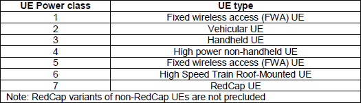
The class number is not a power ranking. 38.101-2 clause 6.2.1.0 states that power classes are specified on the assumption of certain UE types with specific device architectures, and the table names one archetype per class. Classes 1 and 5 name the same architecture, and they differ only in the numbers they have to meet.
That framing explains the shape of the tables that follow. A requirement is written for the device the class assumes, so a handheld is not asked to reach in every direction and a roof mounted antenna is not asked to be small. Without the assumed architecture, the spread between classes looks arbitrary.
Class 1 and class 5 are both fixed wireless access : the same architecture appears twice, with class 5 defined on fewer bands and lower numbers.Class 3 is the handheld case : it is the one a phone has to meet, and 38.101-1 makes it the default class in FR1 unless a band states otherwise.Class 6 is a train roof antenna : that assumption is why its coverage requirement is written over angular areas rather than as a percentile.Class 7 is RedCap : the note below the table adds that RedCap variants of non-RedCap UEs are not precluded, so the class does not fence RedCap in.The architecture is an assumption, not a requirement : nothing stops a device of another shape from meeting the class, and the numbers are what conformance tests.
FR1 Power Class
In FR1 four different power classes are defined and supportability of each power class varies depending on band, but all bands support class 3 by default.
Followings are power class that are supported by frequency range and each band
-
Class 1: Generally targeting fixed-wireless and vehicle-mounted use case and high-power scenarios like public safety, with maximum power around 31 dBm for selected bands, indicating these are for devices requiring the strongest signal transmission capabilities.
- Class 1.5: Targeted for operation in NR bands n41, n77, n78 and n79, addressing the needs of smartphones and fixed wireless access devices, with specific UE requirements including maximum output power and a new duty cycle capability, featuring a maximum power of 29 dBm, which suggests a mid-range power requirement between Class 1 and Class 2.
- Class 2: For NR TDD intra-band Carrier Aggregation (CA) and HPUE(High Power UE), max power is 26 dBm
- Class 3: Identified as the default class unless otherwise specified, with a consistent maximum power of 23 dBm across all bands, suitable for general use cases and possibly optimized for better power efficiency
< 38.101-1 v17.11 : Table 6.2.1-1: UE Power Class >
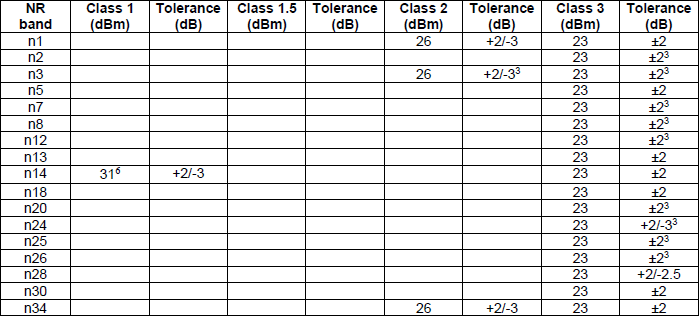
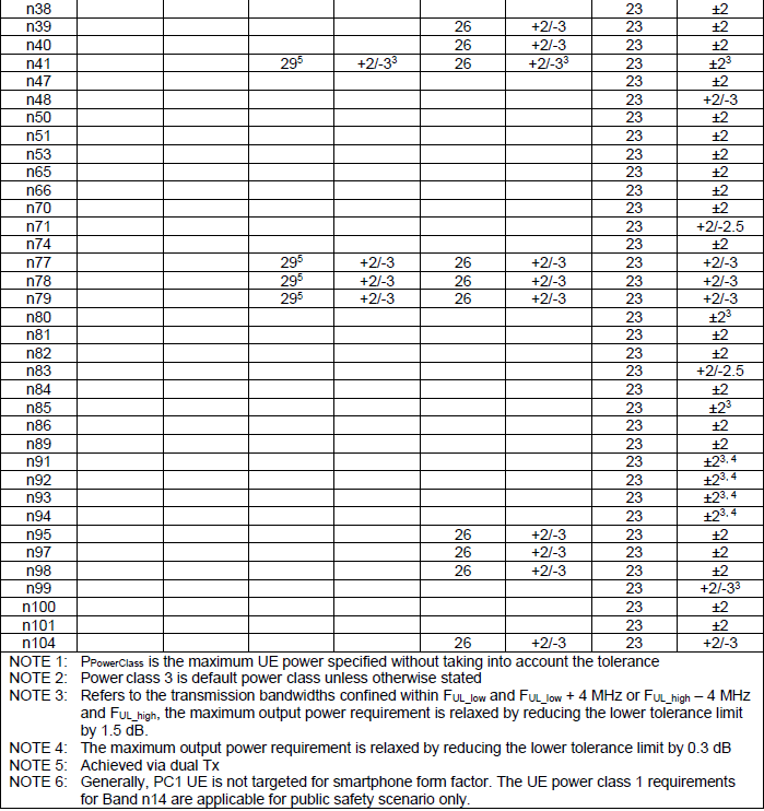
Two things become clear once the whole table is read rather than the summary above it. The first is how empty the class 1 and class 1.5 columns are. Class 1 carries one entry, 31 dBm on n14. The note beneath says power class 1 is generally not targeted at a smartphone form factor, and that it applies to a public safety scenario on that band only.
The second is that class 1.5 covers four bands rather than two. The table gives 29 dBm on n41, n77, n78 and n79, each carrying a note saying the level is achieved via dual Tx. A second transmit chain is what buys the extra 6 dB over class 3, so class 1.5 is a statement about the radio architecture as much as about the number.
Class |
PPowerClass |
Bands in Table 6.2.1-1 |
How it is reached |
|---|---|---|---|
1 |
31 dBm |
n14 only |
Public safety scenario, not a smartphone form factor |
1.5 |
29 dBm |
n41, n77, n78, n79 |
Achieved via dual Tx |
2 |
26 dBm |
n1, n3, n34, n38, n39, n40, n41, n77, n78, n79, n95, n97, n98, n104 |
High power UE on TDD bands |
3 |
23 dBm |
Every band in the table |
The default class unless a band states otherwise |
The tolerance column is worth a glance as well, because it is not symmetric. Most entries read plus 2 minus 2, and several read plus 2 minus 3. A note adds that on transmission bandwidths confined near the edges of the uplink band, the lower tolerance limit is relaxed by a further 1.5 dB. A UE transmitting at the band edge is allowed to fall further below its nominal power.
PPowerClass excludes tolerance : the note under the table defines it as the maximum UE power without taking the tolerance into account.Class 3 is the only class every band defines : the other three columns are sparse, and a band that lists nothing else supports class 3 alone.Class 1 in FR1 is a single band : n14, for public safety, and the specification says so explicitly rather than leaving it to inference.Class 1.5 needs two transmit chains : the note marks every one of its four entries as achieved via dual Tx.The lower tolerance is the one that moves : band edge transmissions relax it by 1.5 dB, and the upper limit of plus 2 dB does not change.
FR2 Power Class
Each power class is tailored to different device requirements and use cases within the 5G NR spectrum, ensuring that a range of devices can operate efficiently and effectively within the set power constraints, from high-power base stations to low-power IoT devices. The specifications for these power classes are critical for compliance with 5G standards and for the optimization of network performance, coverage, and device interoperability.
One comparison is worth making before the seven class blocks. Every class states the same three quantities, so they can be read side by side, and that shows which quantity each class actually changes. The values are taken from Tables 6.2.1.1-1 through 6.2.1.7-3 quoted further down.
Class |
UE type |
Bands |
Min peak EIRP on n257 |
Max TRP / EIRP |
Spherical coverage |
|---|---|---|---|---|---|
1 |
Fixed wireless access |
6 |
40.0 dBm |
35 / 55 dBm |
85 %-tile CDF |
2 |
Vehicular |
6 |
29 dBm |
23 / 43 dBm |
60 %-tile CDF |
3 |
Handheld |
7 |
22.4 dBm |
23 / 43 dBm |
50 %-tile CDF |
4 |
High power non-handheld |
5 |
34 dBm |
23 / 43 dBm |
20 %-tile CDF |
5 |
Fixed wireless access |
3 |
30 dBm |
23 / 43 dBm |
85 %-tile CDF |
6 |
High speed train roof-mounted |
3 |
30 dBm |
23 / 43 dBm |
Over two evaluation areas |
7 |
RedCap |
3 |
16.4 dBm |
23 / 43 dBm |
50 %-tile CDF |
Two columns carry most of the information. Class 1 is the only one allowed above 23 dBm TRP and 43 dBm EIRP, so every other class shares one ceiling and differs only in how close to it the device must get. The spherical coverage column then separates devices that must radiate in most directions from devices that may be aimed.
The percentile is easy to misread, so it is worth stating plainly. A requirement at the 85 percent point means the stated EIRP has to be met over 85 percent of the sphere, which is the strictest on the page. The 20 percent point asked of class 4 is the easiest, and class 6 is not expressed as a percentile at all.
Only class 1 raises the ceiling : 35 dBm TRP and 55 dBm EIRP against 23 and 43 for every other class.Peak and coverage are separate axes : class 4 asks for a high peak and the loosest coverage, and class 5 asks for a lower peak and the tightest.Only class 3 is defined on all seven bands : the others cover between three and six, so band support has to be checked per class.Class 7 is the lowest peak in FR2 : 16.4 dBm on n257, roughly 24 dB below class 1 on the same band.Class 6 is measured over areas, not a sphere fraction : two theta and phi ranges are defined, which follows from the antenna being on a train roof.
Followings are short summary for each power class :
- Power Class 1: Fixed wireless access (FWA) UEs, with high minimum peak EIRP values around 40 dBm and maximum EIRP up to 55 dBm, designed for robust transmission and extensive coverage.
- Power Class 2: Vehicular UEs, featuring minimum peak EIRP values around 29 dBm and maximum EIRP at 43 dBm, balancing coverage and power efficiency for mobility.
- Power Class 3: Handheld UEs, with lower power outputs, minimum peak EIRP in the range of 22.4 to 30.4 dBm, and maximum EIRP of 43 dBm, suitable for general consumer use.
- Power Class 4: High power non-handheld UEs, maintaining minimum peak EIRP levels around 34 dBm and maximum EIRP levels of 43 dBm, focusing on high performance in non-mobile settings.
- Power Class 5: Fixed wireless access (FWA) UEs, with minimum peak EIRP levels set around 30 dBm and a maximum EIRP of 43 dBm, optimizing for stationary setups with efficient energy usage.
- Power Class 6: High Speed Train Roof-Mounted UEs, with moderate minimum peak EIRP at 30 dBm and a consistent maximum EIRP of 43 dBm, tailored for the high-speed connectivity requirements of rail transport.
- Power Class 7: RedCap (Reduced Capability) UEs, the lowest power devices in this list, with minimum peak EIRP at 16.4 dBm and maximum EIRP of 43 dBm, designed for less demanding applications and devices.
Class 1
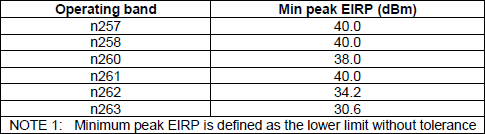
Table 6.2.1.0-1 assigns this class to a fixed wireless access UE, which is why the numbers below are the highest on the page. It is the only FR2 class whose maximum TRP and EIRP exceed 23 dBm and 43 dBm, and the only one whose spherical coverage is measured at the 85 percent point.
The characteristics of power class 1 for each of FR2 band can be summarized as follows :
- Minimum Peak EIRP (Equivalent Isotropically Radiated Power):
- For bands n257, n258 and n261, the minimum peak EIRP is 40.0 dBm.
- For band n260, it is 38.0 dBm
- For band n262, it is 34.2 dBm.
- For band n263, it is lower, at 30.6 dBm.
- The minimum peak EIRP is defined as the lower limit without tolerance.
- Maximum Output Power Limits:
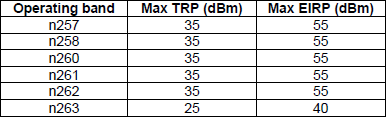
- The maximum Transmission Power (TRP) for bands n257, n258, n260, n261, and n262 is 35 dBm, while for band n263, it is 25 dBm.
- The maximum EIRP for bands n257, n258, n260, n261, and n262 is 55 dBm. For band n263, the maximum EIRP is reduced to 40 dBm.
- UE Spherical Coverage:
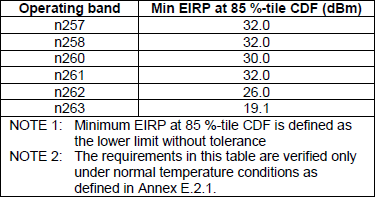
- This table defines the minimum EIRP at 85%-tile Cumulative Distribution Function (CDF) for spherical coverage.
- The values for bands n257, n258 and n261 are set at 32.0 dBm.
- The value for n260 is set at 30.0 dBm
- For band n262, it is 26.0 dBm.
- Band n263 has the lowest with 19.1 dBm.
- The minimum EIRP at 85%-tile CDF is the lower limit without tolerance and these requirements are verified under normal temperature conditions
< 38.101-2 v17.11 Table 6.2.1.1-1: UE minimum peak EIRP for power class 1 >
< 38.101-2 v17.11 Table 6.2.1.1-2: UE maximum output power limits for power class 1 >
< 38.101-2 v17.11 Table 6.2.1.1-3: UE spherical coverage for power class 1 >
Class 2
This class belongs to a vehicular UE. Its peak requirement drops by roughly 11 dB from class 1, and the spherical coverage percentile drops with it, from 85 percent to 60 percent. A roof mounted antenna on a vehicle has fewer blocked directions than a fixed installation aimed at one base station.
The characteristics of power class 2 for each of FR2 band can be summarized as follows :
-
Minimum Peak EIRP:
-
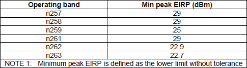
The minimum peak EIRP values for bands n257, n258, n259 and n261 are all set at 29 dBm.
-
For band n262, the value is slightly lower at 22.9 dBm.
-
The lowest value is for band n263 at 22.7 dBm.
-
These values are defined as the lower limit without tolerance.
-
Maximum Output Power Limits:
-
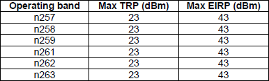
For all listed bands (n257,n258,n259,n261,n262,n263), the maximum TRP (Transmission Power) is 23 dBm.
-
The maximum EIRP for all these bands is 43 dBm.
-
UE Spherical Coverage:
-
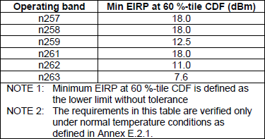
This specifies the minimum EIRP at 60%-tile CDF for spherical coverage.
-
Bands n257, n258 and n261 have a minimum EIRP of 18.0 dBm.
-
Bands n259 has the minimum EIRP values at 12.5
-
Band n262 is set at 11.0 dBm.
-
Band n263 has the lowest value at 7.6 dBm.
-
The minimum EIRP at 60%-tile CDF is defined as the lower limit without tolerance and these requirements are verified under normal temperature conditions
< 38.101-2 v17.11 Table 6.2.1.2-1: UE minimum peak EIRP for power class 2 >
< 38.101-2 v17.11 Table 6.2.1.2-2: UE maximum output power limits for power class 2 >
< 38.101-2 v17.11 Table 6.2.1.2-3: UE spherical coverage for power class 2 >
Class 3
This is the handheld class, and it is the one a phone has to meet. Every FR2 band defines it, its peak requirement is the lowest of the three main classes, and its spherical coverage is measured at only the 50 percent point. A hand and a head block a large fraction of the sphere.
The characteristics of power class 3 for each of FR2 band can be summarized as follows :
-
Minimum Peak EIRP:
-
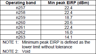
Bands n257,n258 and n261 have a minimum peak EIRP of 22.4 dBm.
-
Band n259 has 18.7 dBm and n260 has 20.6 dBm
-
Band n262 has a lower value of 16.0 dBm, and n263 has the lowest at 14.1 dBm.
-
The minimum peak EIRP is noted as the lower limit without tolerance.
-
Maximum Output Power Limits:
-
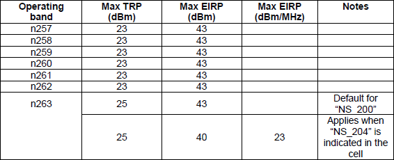
The maximum TRP for bands n257 through n262 is 23 dBm, and for n263, it is slightly higher at 25 dBm.
-
The maximum EIRP for bands n257 through n262 bands is 43 dBm.
-
For band 263, maximum EIRP is 43 when NS 200 and 40 dBm for NS 204.
-
There's also a note for a specific EIRP density limit of 23 dBm/MHz when "NS 204" is indicated.
-
UE Spherical Coverage:
-
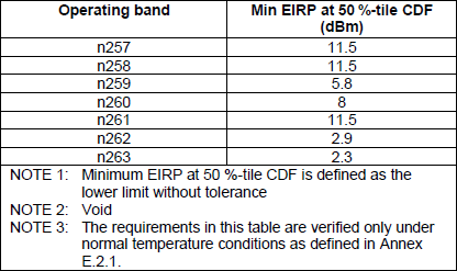
The minimum EIRP at 50%-tile CDF varies across bands: n257, n258 and n261 have 11.5 dBm, n259 has 5.8 dBm, n260 has 8.0 dBm, n262 has 2.9 dBm, and n263 has the lowest at 2.3 dBm.
-
This EIRP is the lower limit without tolerance and is verified under normal temperature conditions
-
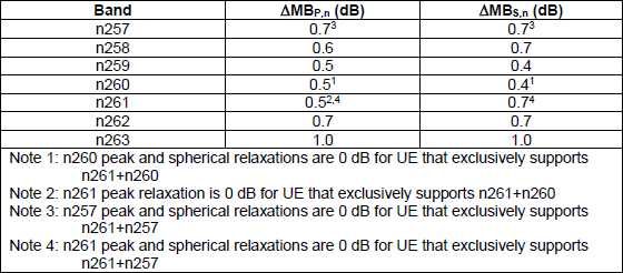
UE Multi-band Relaxation Factors:
-
These factors adjust the minimum required power levels for devices that support multiple bands.
-
The ΔMBPn for bands n257, n258, n259, n260, n261, and n262 ranges between 0.5 to 0.7 dB, while for n263, it is higher at 1.0 dB.
-
The ΔMBSn also ranges from 0.4 to 1.0 dB, depending on the band.
-
Peak and Spherical Relaxations are 0 dB for devices that support only certain combinations of bands
< 38.101-2 v17.11 Table 6.2.1.3-1: UE minimum peak EIRP for power class 3 >
< 38.101-2 v17.11 Table 6.2.1.3-2: UE maximum output power limits for power class 3 >
< 38.101-2 v17.11 Table 6.2.1.3-3: UE spherical coverage for power class 3 >
< 38.101-2 v17.11 Table 6.2.1.3-4: UE multi-band relaxation factors for power class 3 >
Class 4
A high power non-handheld UE sits between the vehicular and handheld cases on peak power, and well below both on coverage. Its spherical requirement is checked at the 20 percent point, the loosest on the page, which suits a device that can be aimed once and left alone.
The characteristics of power class 4 for each of FR2 band can be summarized as follows :
- Minimum Peak EIRP:
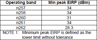
- Bands n257,n258 and n261 have the highest minimum peak EIRP at 34 dBm.
- Band n260 has a minimum of 31 dBm
- Band n262 has the lowest at 28.3 dBm.
- The minimum peak EIRP is noted as the lower limit without tolerance.
- Maximum Output Power Limits:
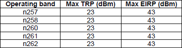
- For all listed bands (n257,n258,n260,n261,n262), the maximum TRP (Transmission Power) is consistent at 23 dBm.
- The maximum EIRP for all these bands is also consistent at 43 dBm.
- UE Spherical Coverage:
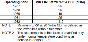
- The minimum EIRP at 20%-tile CDF varies across bands: n257, n258 and n261 are at 25 dBm, n260 is at 19 dBm and n262 has the lowest at 16.2 dBm.
- The minimum EIRP at 20%-tile CDF is defined as the lower limit without tolerance and these requirements are verified under normal temperature conditions
< 38.101-2 Table 6.2.1.4-1: UE minimum peak EIRP for power class 4 >
< 38.101-2 Table 6.2.1.4-2: UE maximum output power limits for power class 4 >
< 38.101-2 Table 6.2.1.4-3: UE spherical coverage for power class 4 >
Class 5
This class is a second fixed wireless access entry, defined on three bands rather than six. Its peak requirement is well below class 1, and yet its spherical coverage returns to the 85 percent point. The combination describes a device with modest gain that still has to see in most directions.
The characteristics of power class 5 for each of FR2 band can be summarized as follows :
- Minimum Peak EIRP:
- Band n257 has a minimum peak EIRP of 30 dBm.
- Band n258 is at 30.4 dBm.
- Band n259 is the lowest at 27.7 dBm.
- These values represent the lower limit without tolerance.
- Maximum Output Power Limits:
- The maximum TRP for bands n257, n258, and n259 is set at 23 dBm.
- The maximum EIRP for all these bands is consistently at 43 dBm.
- UE Spherical Coverage:
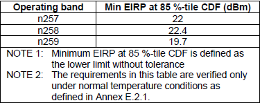
- The minimum EIRP at 85%-tile CDF for band n257 is 22 dBm, for n258 is 22.4 dBm, and for n259 is 19.7 dBm.
- The minimum EIRP values are the lower limits without tolerance and are verified under normal temperature conditions
- UE Multi-band Relaxation Factors:
- For band n257 and n258, the relaxation factors ΔMBPn and ΔMBSn are both 0.7 dB.
- Band n259 has a relaxation factor of 0.5 dB for both ΔMBPn and ΔMBSn.
< 38.101-2 Table 6.2.1.5-1: UE minimum peak EIRP for power class 5 >
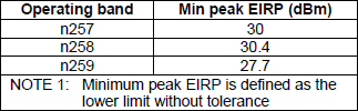
< 38.101-2 Table 6.2.1.5-2: UE maximum output power limits for power class 5 >

< 38.101-2 Table 6.2.1.4-3: UE spherical coverage for power class 5 >
< 38.101-2 Table 6.2.1.5-4: UE multi-band relaxation factors for power class 5 >

Class 6
A high speed train roof-mounted UE is the only class whose coverage is not stated as a percentile. Two angular areas are defined instead, and the requirement applies over those areas rather than over a fraction of the sphere. A train antenna only has to cover the directions the track runs in.
The characteristics of power class 6 for each of FR2 band can be summarized as follows :
- Minimum Peak EIRP:
- Bands n257 and n261 have a minimum peak EIRP of 30 dBm.
- Band n268 has a slightly higher minimum peak EIRP of 30.4 dBm.
- The minimum peak EIRP is defined as the lower limit without tolerance.
- Maximum Output Power Limits:
- All three bands, n257, n258, and n261, have the same maximum TRP of 23 dBm.
- The maximum EIRP for these bands is also the same at 43 dBm.
- UE Spherical Coverage Evaluation:
- For bands n257 and n261, the minimum EIRP over UE spherical coverage evaluation areas is 20 dBm.
- Band n258 also has the minimum EIRP at 20.4 dBm.
- These minimum EIRP values are the lower limits without tolerance and are verified under normal temperature conditions.
- UE Spherical Coverage Evaluation Areas:
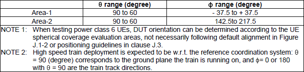
- The spherical coverage evaluation areas are divided into two areas with different ranges for the θ (theta) and φ (phi) angles.
- Area-1 has a θ range of 90 to 60 degrees and a φ range of -37.5 to +37.5 degrees.
- Area-2 has a θ range of 90 to 60 degrees and a φ range of 142.5 to 217.5 degrees.
- There are additional notes indicating that the orientation of the Device Under Test (DUT) can be determined according to the UE spherical coverage evaluation areas and that for high-speed train deployments, the reference coordination system's θ is expected to be with respect to the ground plane the train is running on.
- UE Multi-band Relaxation Factors:
- For all bands (n257, n258, and n261), the multi-band relaxation factors ΔMBPn and ΔMBSn are both 0.7 dB.
< 38.101-2 Table 6.2.1.6-1: UE minimum peak EIRP for power class 6 >
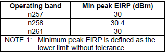
< 38.101-2 Table 6.2.1.6-2: UE maximum output power limits for power class 6 >

< 38.101-2 Table 6.2.1.6-3: UE spherical coverage for power class 6 >
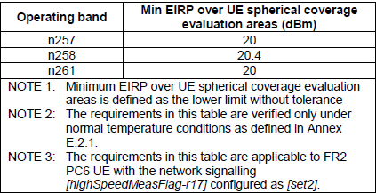
< 38.101-2 Table 6.2.1.6-3a: UE spherical coverage evaluation areas for power class 6 >
< 38.101-2 Table 6.2.1.6-4: UE multi-band relaxation factors for power class 6 >

Class 7
RedCap is the reduced capability device, and this class carries the lowest peak requirement in FR2. Its spherical coverage returns to the 50 percent point used by handhelds, so what separates it from class 3 is sensitivity rather than the shape of the coverage.
The characteristics of power class 7 for each of FR2 band can be summarized as follows :
- Minimum Peak EIRP:
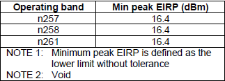
- For all three bands (n257, n258, n261), the minimum peak EIRP is set at 16.4 dBm.
- The minimum peak EIRP is described as the lower limit without tolerance.
- Maximum Output Power Limits:
- The maximum TRP for these bands is consistent at 23 dBm.
- The maximum EIRP is also the same across the bands at 43 dBm.
- UE Spherical Coverage:
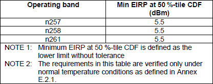
- For spherical coverage, the minimum EIRP at 50%-tile CDF is significantly lower:
- For bands n257 and n258, it is 5.5 dBm.
- For band n261, it is slightly higher at 5.5 dBm.
- This minimum EIRP at 50%-tile CDF is the lower limit without tolerance and is verified under normal temperature conditions
< 38.101-2 Table 6.2.1.7-1: UE minimum peak EIRP for power class 7 >
< 38.101-2 Table 6.2.1.7-2: UE maximum output power limits for power class 7 >

< 38.101-2 Table 6.2.1.7-3: UE spherical coverage for power class 7 >
Reference
- High Power UEs - 3GPP
- 38.101-1 : NR - User Equipment (UE) radio transmission and reception, Part 1, Range 1 Standalone. Clause 6.2.1 holds the FR1 power classes, and Table 6.2.1-1 is quoted above from v17.11. The current published version is v20.0.0.
- 38.101-2 : NR - User Equipment (UE) radio transmission and reception, Part 2, Range 2 Standalone. Clauses 6.2.1.0 to 6.2.1.7 hold the FR2 power classes, and every FR2 table above is quoted from v17.11. The current published version is v20.0.0.