Everything on this page happens after the UE is already registered. Registration gets the UE known to the network, and it gets a security context in place. It does not give the UE anywhere to send data. PDU session establishment is the procedure that closes that gap, and it is the point where a UE stops being merely attached and starts being usable.
|
Followings are the list of the topics on this note.
- PDU Session Establishment in Detail
- Before you move on
- Signaling Sequence
- < Case A > Normal PDU Establishment
- < Case B > No PDU Session Establishment Accept
- < Case C > PDU SESSION ESTABLISHMENT REJECT
- Message Structure
- PDU Session Establishment Request
- PDU Session Establishment Accept
- UL NAS Transport
- DL NAS Transport
- 5GSM capability
- 5GSM cause
- Always-on PDU session
- Always-on PDU session indication
- Always-on PDU session requested
- Use cases of Always-on PDU session
- How to disable Always-on Session after it is enabled ?
- EAP message
- Extended protocol configuration options
- GPRS Timer
- Mapped EPS bearer contexts
- PDU address
- PDU session type
- QoS rules
- Request type
- Session-AMBR
- SM PDU DN request container
- S-NSSAI
- SSC (Session and Service Continuity) mode
- Payload container type
- MA PDU session information
- Get the Test Procedure and Log / Amarisoft TechAcademy
- Reference
- YouTube
PDU Session Establishment in Detail
PDU Session Establishement is equivalent to PDN Establishment in LTE. Main purpose of this process is to assign UE IP and inform the UE of various the IP address of various corenetwork components (application layer component). With respect of IP allocation, PDU session establishment correponds to PDN connectivity procedure in LTE. Another important role of PDU Session Establishment is to establish QoS Flow. The QoS procedure will be explained in detail in this note (QoS / QFI / QRI).
As mentioned above, main functionality of PDU Session Establishment will be treated in a few separate notes. In this note, I will focus mostly on the message structure of PDU Session Establishment signaling.
One property of the procedure shapes everything that follows. It is always initiated by the UE. 24.501 defines no message by which the network establishes a PDU session on its own. A session that appears without a UE request has therefore not appeared at all. The network can modify a session and it can release one, and both of those have network-initiated forms. Establishment does not.
The UE marks its attempt with a procedure transaction identity. It allocates a PTI value that is not currently in use, puts it in the request, and keeps it until the procedure ends. That value pairs an accept or a reject with the request that caused it. It is also why several PDU session procedures can run at once without being confused for one another.
PDU session establishment is UE-initiated only : the network has no message to create a session, so it can only invite the UE to ask by other means.The PTI pairs a response with its request : it is allocated by the UE, echoed by the network, and released when the procedure ends.The session ID and the PTI are different things : PDU session ID names the session for its whole life, while the PTI names one procedure acting on it.
Before you move on
In this note, I would mostly focus on the two NAS messages between UE and the Network (especially AMF) and contents of the two messages, but there are a lot of other network components and interactions among those components happen. It is difficult to describe about every components, interactions and the functionalities in single page. So I wrote a few separate notes that are related to the functionalities of PDU Establishment process as listed below. Depending on your own interest and needs, follow through these notes in your own order.. but whatever you pick as the first note, you would need to go through all of these notes as you go deeper into this subject (i.e, PDU establishment process).
- The key network component that is in charge of PDU establishment process is SMF and SMF perform interactions with other components to complete this process. If you want to understand overall procedure on what's happening on core network side for PDU establishment process, check out the note on SMF first.
- In terms of protocol, PDU Session is managed and controlled by 5GSM (5G Session Management). So it would be good to have detailed understanding on 5GSM functionality. Check out the note of 5GSM.
- Since PDU establishment is related to so many different functionality, it would be hard to grasp the big picture of it. It would be helpful to categorize the functionality of PDU session into a couple of group as follows.
- In between this NAS message and Core Network, there is an interface protocol (N2, NGAP) is involved. Check out this note for the details.
Signaling Sequence
A PDU session establishment attempt has three possible endings, and the tables below cover all three. The UE sends the same request every time. What differs is what comes back: an accept, a reject, or nothing at all. One timer decides the third case. T3580 runs for 16 seconds from the moment the request is sent. What the UE does next depends on whether a message stops that timer or it expires on its own.
According to 24.501 - 6.4.1.2 UE-requested PDU session establishment procedure initiation goes as follows.
Case A : Normal PDU Establishment
This is the path a working network takes. The request travels up inside a UL NAS Transport, the accept comes back inside a DL NAS Transport, and T3580 stops when the accept arrives. The UE then releases the allocated PTI and treats the session as established.
|
Direction |
Message |
UE Timer |
NW Timer |
|
UE -> NW(SMF) |
ULInformationTransfer + UL NAS Transport |
T3580 Start |
|
|
UE <- NW(SMF) |
DLInformationTransfer + DL NAS Transport |
T3580 Stop |
|
Case B : No PDU Session Establishment Accept
Nothing comes back here, so the timer decides the outcome rather than a message. On the first expiry of T3580 the UE retransmits the same request and restarts the timer. It repeats that up to four times. On the fifth expiry the UE aborts the procedure, releases the PTI and enters the state PROCEDURE TRANSACTION INACTIVE.
|
Direction |
Message |
UE Timer |
NW Timer |
|
UE -> NW(SMF) |
ULInformationTransfer + UL NAS Transport |
T3580 Start |
|
|
UE <- NW(SMF) |
No PDU SESSION ESTABLISMENT ACCEPT |
T3580 Expire |
|
Case C : PDU SESSION ESTABLISHMENT REJECT
A reject is a faster answer than a timeout, and a more useful one. T3580 stops the moment the reject arrives, exactly as it would for an accept, and the PTI is released the same way. The difference is the 5GSM cause value the reject carries. That value is what tells the UE whether to retry, to change the request, or to stop asking.
|
Direction |
Message |
UE Timer |
NW Timer |
|
UE -> NW(SMF) |
ULInformationTransfer + UL NAS Transport |
T3580 Start |
|
|
UE <- NW(SMF) |
DLInformationTransfer + DL NAS Transport + PDU SESSION ESTABLISHMENT REJECT |
T3580 Stop |
|
Following is a table listing various reject cause and the expected UE behavior based on 24.501-6.4.1.4, 6.4.1.7 and 24.501-AnnexA. I put only high level and most critical (most critical to me) in the 'Expected UE behavior' column. There are much more futher details specified in the specification.
|
Reject Cause |
Expected UE Behavior |
|
#8 operator determined barring; (24.501-6.4.1.4) |
|
|
#26 insufficient resources (24.501-6.4.1.4,6.4.1.7) |
The SMF may include a Back-off timer value IE in the PDU SESSION ESTABLISHMENT REJECT message when the 5GSM cause value #26"insufficient resources" is included in the PDU SESSION ESTABLISHMENT REJECT message. If the 5GSM cause value is #26"insufficient resources" and the PDU SESSION ESTABLISHMENT REQUEST message was received from a UE configured for high priority access in selected PLMN or the request type is set to "initial emergency request" or "existing emergency PDU session", the network shall not include a Back-off timer value IE. If the PDU session cannot be established due to resource unavailability in the UPF, the SMF shall include the 5GSM cause value #26 "insufficient resources" in the 5GSM cause IE of the PDU SESSION ESTABLISHMENT REJECT message. 5G access network cannot forward the message: If the SMF determines based on content of the n2SmInfo attribute specified in 3GPP TS 29.502 that the DL NAS TRANSPORT message carrying the PDU SESSION ESTABLISHMENT ACCEPT was not forwarded to the UE by the 5G access network, then the SMF shall reject the PDU session establishment procedure with the 5GSM cause set to #26 "insufficient resources" in the PDU SESSION ESTABLISHMENT REJECT message. |
|
#27 missing or unknown DNN (24.501-6.4.1.4) |
|
|
#28 unknown PDU session type (24.501-6.4.1.4) |
If the PDU SESSION ESTABLISHMENT REQUEST message includes a PDU session type IE set to "IPv6", and the subscription, the SMF configuration, or both, support none of "IPv4" and "IPv6" PDU session types for the requested DNN, the SMF shall include the 5GSM cause value #28 "unknown PDU session type" in the 5GSM cause IE of the PDU SESSION ESTABLISHMENT REJECT message. If the PDU SESSION ESTABLISHMENT REQUEST message includes a PDU session type IE set to "IPv4", and the subscription, the SMF configuration, or both, support none of "IPv4" and "IPv6" PDU session types for the requested DNN, the SMF shall include the 5GSM cause value #28 "unknown PDU session type" in the 5GSM cause IE of the PDU SESSION ESTABLISHMENT REJECT message. If the PDU SESSION ESTABLISHMENT REQUEST message includes a PDU session type IE set to "IPv4v6", and the subscription, the SMF configuration, or both, support none of "IPv4v6", "IPv4" and "IPv6" PDU session types for the requested DNN, the SMF shall include the 5GSM cause value #28 "unknown PDU session type" in the 5GSM cause IE of the PDU SESSION ESTABLISHMENT REJECT message. If the PDU SESSION ESTABLISHMENT REQUEST message includes a PDU session type IE set to "Unstructured" or "Ethernet", and the subscription, the SMF configuration, or both, do not support the PDU session type for the requested DNN, the SMF shall include the 5GSM cause value #28 "unknown PDU session type" in the 5GSM cause IE of the PDU SESSION ESTABLISHMENT REJECT message. |
|
#29 user authentication or authorization failed (24.501-6.4.1.4,6.4.1.7) |
If the DN authentication of the UE was performed and completed unsuccessfully, the SMF shall include the 5GSM cause value #29 "user authentication or authorization failed" in the 5GSM cause IE of the PDU SESSION ESTABLISHMENT REJECT message and shall set the EAP message IE of the PDU SESSION ESTABLISHMENT REJECT message to an EAP-failure message as specified in IETF RFC 3748, provided by the DN. The information for the PDU session authentication and authorization by the external DN in PDU DN request container is not compliant with local policy and user's subscription data If the PDU session being established is a non-emergency PDU session, the PDU session authentication and authorization by the external DN is required due to local policy and user's subscription data and the information for the PDU session authentication and authorization by the external DN in PDU DN request container is not compliant with local policy and user's subscription data, the SMF shall reject the PDU session establishment request including the 5GSM cause #29 "user authentication or authorization failed", in the PDU SESSION ESTABLISHMENT REJECT message. |
|
#31 request rejected, unspecified (24.501-6.4.1.7) |
If the received request type is "initial emergency request" and there is already another emergency PDU session for the UE, the SMF shall reject the PDU SESSION ESTABLISHMENT REQUEST message with 5GSM cause #31 "request rejected, unspecified" or release locally the existing emergency PDU session and proceed the new PDU SESSION ESTABLISHMENT REQUEST message |
|
#32 service option not supported (24.501-6.4.1.4) |
|
|
#33 requested service option not subscribed (24.501-6.4.1.4) |
|
|
#35 PTI already in use (24.501-6.4.1.4) |
|
|
#38 network failure (24.501-6.4.1.4) |
|
|
#46 out of LADN service area (24.501-6.4.1.4) |
If the UE requests a PDU session establishment for an LADN when the UE is located outside of the LADN service area, the SMF shall include the 5GSM cause value #46 "out of LADN service area" in the 5GSM cause IE of the PDU SESSION ESTABLISHMENT REJECT message. |
|
#50 PDU session type IPv4 only allowed (24.501-6.4.1.4) |
If the PDU SESSION ESTABLISHMENT REQUEST message includes a PDU session type IE set to "IPv6", and the subscription, the SMF configuration, or both, are limited to IPv4 only for the requested DNN, the SMF shall include the 5GSM cause value #50 "PDU session type IPv4 only allowed" in the 5GSM cause IE of the PDU SESSION ESTABLISHMENT REJECT message. |
|
#51 PDU session type IPv6 only allowed (24.501-6.4.1.4) |
If the PDU SESSION ESTABLISHMENT REQUEST message includes a PDU session type IE set to "IPv4", and the subscription, the SMF configuration, or both, are limited to IPv6 only for the requested DNN, the SMF shall include the 5GSM cause value #51 "PDU session type IPv6 only allowed" in the 5GSM cause IE of the PDU SESSION ESTABLISHMENT REJECT message. |
|
#54 PDU session does not exist (24.501-6.4.1.7) |
UE-requested PDU session establishment with request type "existing PDU session" or "existing emergency PDU session" for a PDU session that does not exist: If the SMF receives a PDU SESSION ESTABLISHMENT REQUEST message with request type set to "existing PDU session" or "existing emergency PDU session", and the SMF does not have any information about that PDU session, then the SMF shall reject the PDU session establishment procedure with the 5GSM cause set to #54 "PDU session does not exist" in the PDU SESSION ESTABLISHMENT REJECT message. |
|
#67 insufficient resources for specific slice and DNN (24.501-6.4.1.4) |
The SMF may include a Back-off timer value IE in the PDU SESSION ESTABLISHMENT REJECT message when the 5GSM cause value #67 "insufficient resources for specific slice and DNN" is included in the PDU SESSION ESTABLISHMENT REJECT message. If the 5GSM cause value is #67 "insufficient resources for specific slice and DNN" and the PDU SESSION ESTABLISHMENT REQUEST message was received from a UE configured for high priority access in selected PLMN or the request type is "initial emergency request" or "existing emergency PDU session", the network shall not include a Back-off timer value IE. |
|
#68 not supported SSC mode (24.501-6.4.1.4) |
If the PDU SESSION ESTABLISHMENT REQUEST message contains the SSC mode IE indicating an SSC mode not supported by the subscription, the SMF configuration, or both of them, and the SMF decides to rejects the PDU session establishment, the SMF shall include the 5GSM cause value #68 "not supported SSC mode" in the 5GSM cause IE and the SSC modes allowed by SMF in the Allowed SSC mode IE of the PDU SESSION ESTABLISHMENT REJECT message. |
|
#69 insufficient resources for specific slice (24.501-6.4.1.4) |
The SMF may include a Back-off timer value IE in the PDU SESSION ESTABLISHMENT REJECT message when the 5GSM cause #69 "insufficient resources for specific slice" is included in the PDU SESSION ESTABLISHMENT REJECT message. If the 5GSM cause value is #69 "insufficient resources for specific slice" and the PDU SESSION ESTABLISHMENT REQUEST message was received from a UE configured for high priority access in selected PLMN or the request type is "initial emergency request" or "existing emergency PDU session", the network shall not include a Back-off timer value IE. |
|
#70 missing or unknown DNN in a slice (24.501-6.4.1.4) |
|
|
#82 maximum data rate per UE for user-plane integrity protection is too low (24.501-6.4.1.4) |
In 3GPP access, if the operator's configuration requires user-plane integrity protection for the PDU session and, the maximum data rate per UE for user-plane integrity protection supported by the UE for uplink or the maximum data rate per UE for user-plane integrity protection supported by the UE for downlink, or both, are lower than required by the operator's configuration, the SMF shall include the 5GSM cause value #82 "maximum data rate per UE for user-plane integrity protection is too low" in the 5GSM cause IE of the PDU SESSION ESTABLISHMENT REJECT message. |
|
#95 111 protocol errors |
|
Message Structure
A PDU session message never travels on its own. 5GSM is a separate protocol from 5GMM, and it has no transport of its own. Every PDU session message is therefore carried inside a 5GMM message as a payload container. That nesting is why a capture shows three layers where a reader might expect one.
In this section the overall message structure and functionalities of important IE (Information Element) will be explained.
The overall structure of PDU Session related message is as follows :
NGAP : Downlink NAS Transport -> NAS : DL NAS Transport -> PDU Session related Message
NGAP : Uplink NAS Transport -> NAS : UL NAS Transport -> PDU Session related Message
If you want to see the contents of full log with Amarisoft Log viewer, go to LogAnalysis section and click on 'Sample Log' in this tutorial of Amarisoft TechAcademy.
Two consequences of that nesting are worth stating before the messages themselves. Integrity protection is never applied to a 5GSM message directly. It is applied to the 5GMM message carrying it, so a PDU session request inherits its security from the registration that came before it.
The second consequence is that the two procedures succeed and fail independently. A PDU session establishment can be rejected inside a UL NAS Transport that was itself delivered and acknowledged normally. Reading one message and one outcome is the usual mistake here.
The payload container type names the passenger : for PDU session signalling it is set to N1 SM information, and that is the field a decoder uses to parse what follows.5GSM security is inherited, not negotiated : the 5GSM message carries no protection of its own, so a plain 5GMM envelope means a plain PDU session message inside it.One message can carry two outcomes : the 5GMM transport can succeed while the 5GSM procedure inside it is rejected, and a log shows both on the same frame.
PDU Session Establishment Request
When UE needs to establish a PDU session, it sends to AMF "PDU Session Establishment Request" message containing the information as listed below and AMF forward it to an SMF.
PDU Session Establishment Request (24.501 - 8.3.1.1)
PDU seesion Type (24.501 - 9.11.4.11)
SSC mode (24.501 - 9.11.4.16)
5GSM capability (24.501 - 9.11.4.1)
Maximum number of supported packet filters (24.501 - 9.11.4.9)
Always-on PDU session requested (24.501 - 9.11.4.4)
SM PDU DN request container (24.501 - 9.11.4.15)
Extended protocol configuration options (24.501 - 9.11.4.6)
Request Type (24.501-9.11.3.47)
Example 01
The hex string below is the whole NAS message as it travels on the air interface, and the decode under it unpacks the same bytes. Read the two together. The outer header is 5GMM, and the PDU session request itself only begins after the payload container type says N1 SM information.
This is a sample message from the log provided by Amarisoft.
{
  message c1: ulInformationTransfer: {
    criticalExtensions ulInformationTransfer: {
      dedicatedNAS-Message '7E02FF096300027E006701001E2E0509C1FFFF93A17B001380000A00000
                                      200000100000C00000300000D00120581250403696D73'H
    }
  }
}
The decoded contents of the above NAS message is as below :
Message: UL NAS transport
Data:
Protocol discriminator = 0x7e (5GS Mobility Management)
Security header = 0x2 (Integrity protected and ciphered)
Auth code = 0xff096300
Sequence number = 0x02
Protocol discriminator = 0x7e (5GS Mobility Management)
Security header = 0x0 (Plain 5GS NAS message, not security protected)
Message type = 0x67 (UL NAS transport)
Payload container type = 1 (N1 SM information)
Payload container:
  Protocol discriminator = 0x2e (5GS Session Management)
  PDU session identity = 5
  Procedure transaction identity = 9
  Message type = 0xc1 (PDU session establishment request)
  Integrity protection maximum data data:
    Maximum data rate per UE for user-plane integrity protection
                                     for uplink = 0xff (Full data rate)
    Maximum data rate per UE for user-plane integrity protection
                                     for downlink = 0xff (Full data rate)
  PDU session type = 0x3 (IPv4v6)
  SSC mode = 0x1 (1)
  Extended protocol configuration options:
    Ext = 1
    Configuration protocol = 0
    Protocol ID = 0x000a (IP address allocation via NAS signalling)
    Data =
    Protocol ID = 0x0002 (IM CN Subsystem Signaling Flag)
    Data =
    Protocol ID = 0x0001 (P-CSCF IPv6 Address Request)
    Data =
    Protocol ID = 0x000c (P-CSCF IPv4 Address Request)
    Data =
    Protocol ID = 0x0003 (DNS Server IPv6 Address Request)
    Data =
    Protocol ID = 0x000d (DNS Server IPv4 Address Request)
    Data =
PDU session ID = 5
Request type = 0x1 (initial request)
DNN = "ims"
PDU Session Establishment Accept
The accept is where the network stops taking requests and starts issuing decisions. Almost every IE in it is either the answer to something the UE asked for, or a parameter the UE never asked for and now has to use. Note how many of the names below begin with Selected or Authorized, because that prefix is the difference between this message and the request.
PDU Session Establishment Accept (24.501 - 8.3.2.1)
PDU Session ID (24.501 - 9.4)
Selected PDU session type (24.501 - 9.11.4.11)
Selected SSC mode (24.501 - 9.11.4.16)
Authorized QoS rules (24.501 - 9.11.4.13)
Session AMBR (24.501 - 9.11.4.14)
5GSM cause (24.501 - 9.11.4.2)
PDU address (24.501 - 9.11.4.10)
RQ Timer Value (24.501 - 9.11.2.3)
S-NSSAI (24.501 - 9.11.2.8)
Always-on PDU session indication (24.501 - 9.11.4.3)
Mapped EPS bearer contexts (24.501 - 9.11.4.8)
EAP message (24.501 - 9.11.2.2)
Authorized QoS flow descriptions (24.501 - 9.11.4.12)
Extended protocol configuration options (24.501 - 9.11.4.6)
DNN (24.501 - 9.11.2.1B)
Example 01 : PDU Address, DNN,QoS, No Slice Info
This example is the simpler of the two, and the difference is worth knowing before reading either. It carries a PDU address, a DNN and QoS rules, and it carries no slice information at all. That is what a single-slice deployment looks like in a log.
This is a sample message from the log provided by Amarisoft.
{
  message c1: dlInformationTransfer: {
    rrc-TransactionIdentifier 0,
    criticalExtensions dlInformationTransfer: {
      dedicatedNAS-Message '7E0206FC019B027E0054431081C176589E9EBFCD7490B34CBFBFE56
                            B450981C176589E9EBFCD7446404791118261539040490100'H
    }
  }
}
Protocol discriminator = 0x7e (5GS Mobility Management)
Security header = 0x2 (Integrity protected and ciphered)
Auth code = 0x66f143b0
Sequence number = 0x03
Protocol discriminator = 0x7e (5GS Mobility Management)
Security header = 0x0 (Plain 5GS NAS message, not security protected)
Message type = 0x68 (DL NAS transport)
Payload container type = 1 (N1 SM information)
Payload container:
  Protocol discriminator = 0x2e (5GS Session Management)
  PDU session identity = 5
  Procedure transaction identity = 9
  Message type = 0xc2 (PDU session establishment accept)
  Selected PDU session type = 0x3 (IPv4v6)
  Selected SSC mode = 0x1 (1)
  Authorized QoS rules:
    QoS rule 1:
      QoS rule identifier = 1
      Rule operation code = 1 (create new QoS rule)
      DQR = 1 (the QoS rule is the default QoS rule)
      Number of packet filters = 1
      Packet filter identifier = 15
        Packet filter direction = 3 (bidirectional)
        Match-all
      QoS rule precedence = 255
      QFI = 1
  Session AMBR:
    Session-AMBR for downlink = 3000000 kbps
    Session-AMBR for uplink = 1000000 kbps
  PDU address:
    PDU session type = 3 (IPv4v6)
    IPv6 = ::2001:468:3000:1
    IPv4 = 192.168.4.2
  Authorized QoS flow descriptions:
    QoS flow description 1:
      QFI = 1
      Operation code = 1 (create new QoS flow description)
      E = 1 (parameters list is included)
      Number of parameters = 1
      5QI = 5
  Extended protocol configuration options:
    Ext = 1
    Configuration protocol = 0
    Protocol ID = 0x000d (DNS Server IPv4 Address)
    Data = 8.8.8.8
    Protocol ID = 0x0003 (DNS Server IPv6 Address)
    Data = 2001:4860:4860:0:0:0:0:8888
    Protocol ID = 0x000c (P-CSCF IPv4 Address)
    Data = 192.168.4.1
    Protocol ID = 0x0001 (P-CSCF IPv6 Address)
    Data = 2001:468:3000:1:0:0:0:0
    Protocol ID = 0x0002 (IM CN Subsystem Signaling Flag)
    Data =
  DNN = "ims.mnc001.mcc001.gprs"
  PDU session ID = 5
Example 02 : PDU Address, DNN,QoS, Slice Info
The second example carries the same parameters as the first and adds the S-NSSAI. Comparing the two decodes is the quickest way to see where slice information sits inside the accept, and how little else changes when it is present.
Protocol discriminator = 0x2e (5GS Session Management)
PDU session identity = 1
Procedure transaction identity = 5
Message type = 0xc2 (PDU session establishment accept)
Selected PDU session type = 0x1 (IPv4)
Selected SSC mode = 0x1 (1)
Authorized QoS rules:
QoS rule 1:
QoS rule identifier = 1
Rule operation code = 1 (create new QoS rule)
DQR = 1 (the QoS rule is the default QoS rule)
Number of packet filters = 1
Packet filter identifier = 15
Packet filter direction = 3 (bidirectional)
Match-all
QoS rule precedence = 255
QFI = 1
Session AMBR:
Session-AMBR for downlink = 5000 Mbps
Session-AMBR for uplink = 2000000 kbps
5GSM cause = 0x32 (PDU session type IPv4 only allowed)
PDU address:
SI6LLA = 0
PDU session type = 1 (IPv4)
IPv4 = 192.168.3.2
Length of S-NSSAI contents = 1 (SST)
SST = 0x01
Mapped EPS bearer context 1:
EPS bearer identity = 5
Operation code = 1 (create new EPS bearer)
E = 1 (parameters list is included)
Number of EPS parameters = 2
Mapped EPS QoS parameters:
QCI = 9
APN-AMBR:
APN-AMBR for downlink = 4864000000 bits
APN-AMBR for uplink = 1792000000 bits
Authorized QoS flow descriptions:
QoS flow description 1:
QFI = 1
Operation code = 1 (create new QoS flow description)
E = 1 (parameters list is included)
Number of parameters = 2
5QI = 9
EPS bearer identity = 5
Extended protocol configuration options:
Ext = 1
Configuration protocol = 0
Protocol ID = 0x8021 (IPCP)
Data = 03 00 00 0a 81 06 08 08 08 08
Protocol ID = 0x000d (DNS Server IPv4 Address)
Data = 8.8.8.8
DNN = "internet.mnc001.mcc001.gprs"
UL NAS Transport
This is the envelope, not the content. UL NAS Transport is a 5GMM message, and its job is to carry something else upward to the AMF. The payload container type says what that something is, and for PDU session signalling it says N1 SM information.
UL NAS transport (24.501 - 8.2.10.1)
Extended protocol discriminator (24.501 - 9.2)
Security header type (24.501 - 9.3)
UL NAS TRANSPORT message identity (24.501 - 9.7)
Payload container type (24.501 - 9.11.3.40)
Payload container (24.501 - 9.11.3.39)
PDU session ID (24.501 - 9.11.3.41)
Old PDU session ID (24.501 - 9.11.3.41)
Request Type (24.501 - 9.11.3.47)
S-NSSAI (24.501 - 9.11.2.8)
DNN (24.501 - 9.11.2.1B)
Additional information (24.501 - 9.11.2.1)
MA PDU session information (24.501 - 9.11.3.31A)
Release assistance indication (24.501 - 9.11.3.46A)
Three of the IEs above decide where the AMF sends the container rather than what the container says. Request Type, S-NSSAI and DNN together let the AMF choose an SMF without decoding the 5GSM message inside it. That is the whole point of repeating them on the outside of the envelope.
The two PDU session ID fields do a similar job at a smaller scale. PDU session ID says which session the container belongs to. Old PDU session ID appears only when an existing session is being moved rather than created, which is how a handover between 3GPP and non-3GPP access is signalled.
The AMF routes without decoding : Request Type, S-NSSAI and DNN sit outside the container so the AMF can select an SMF from the 5GMM layer alone.Old PDU session ID means a move, not a create : its presence is the marker that the UE is relocating a session between access types.The container is opaque to the AMF : everything the AMF needs is duplicated in the outer IEs, and the 5GSM payload is passed through untouched.
DL NAS Transport
This is the same envelope in the other direction. The AMF uses it to deliver a 5GSM message down to the UE, and the payload container type again says what is inside. Two IEs exist here that have no counterpart in the uplink form, and both report failure rather than content.
DL NAS transport (24.501 - 8.2.11.1)
Extended protocol discriminator (24.501 - 9.2)
Security header type (24.501 - 9.3)
DL NAS TRANSPORT message identity (24.501 - 9.7)
Payload container type (24.501 - 9.11.3.40)
Payload container (24.501 - 9.11.3.39)
PDU session ID (24.501 - 9.11.3.41)
Additional information (24.501 - 9.11.2.1)
5GMM cause (24.501 - 9.11.3.2)
Back-off timer value (24.501 - 9.11.2.5)
Those two are 5GMM cause and Back-off timer value. They appear when the AMF could not deliver the container at all, rather than when the SMF rejected what was in it. The distinction matters when reading a log. A 5GMM cause in a DL NAS Transport is a routing or transport failure at the mobility layer. A 5GSM cause inside a PDU Session Establishment Reject is a decision taken by the SMF about the session itself.
A 5GMM cause here is not a session rejection : it reports that the transport failed, so the SMF may never have seen the request.Back-off timer value throttles the retry : the UE waits for it before asking again, which is how the network reduces load without rejecting every attempt.
5GSM capability
This is an information element(IE) is to convey information about the supported features and capabilities of the User Equipment (UE) or the network during the PDU session establishment procedure. This allows the network to establish a PDU session that is optimized for the UE's features and capabilities, ensuring a seamless and efficient user experience. If the UE's capabilities are not compatible with the network's requirements or the requested service, the network may reject the PDU session establishment with an appropriate 5GSM cause value.
RqoS
0 Reflective QoS not supported
1 Reflective QoS supported
Multi-homed IPv6 PDU session (MH6-PDU)
0 Multi-homed IPv6 PDU session not supported
1 Multi-homed IPv6 PDU session supported
Brief description of the configuration listed above are :
0: Reflective QoS not supported - Indicates that the UE does not support reflective QoS, which means that the UE requires explicit signaling from the network to determine the QoS parameters.
1: Reflective QoS supported - Specifies that the UE supports reflective QoS, allowing it to derive the QoS parameters from the network without explicit signaling.
0: Multi-homed IPv6 PDU session not supported - Indicates that the UE does not support multi-homed IPv6 PDU sessions, which means it cannot maintain multiple IPv6 addresses and multiple paths for a single PDU session.
1: Multi-homed IPv6 PDU session supported - Specifies that the UE supports multi-homed IPv6 PDU sessions, allowing it to maintain multiple IPv6 addresses and multiple paths for a single PDU session, improving resilience and load balancing.
5GSM cause
This is is an information element(IE) used in 5G PDU Establishment messages and other 5G Session Management procedures to convey information about the success or failure of a specific procedure. It provides a cause code that indicates the reason behind the outcome of the procedure, whether it's successful, rejected, or encounters an error.
5GSM cause IEI
Cause value
Operator determined barring
Insufficient resources
Missing or unknown DNN
Unknown PDU session type
User authentication or authorization failed
Request rejected, unspecified
Service option not supported
Requested service option not subscribed
Service option temporarily out of order
PTI already in use
Regular deactivation
Network failure
Reactivation requested
Invalid PDU session identity
Semantic errors in packet filter(s)
Syntactical error in packet filter(s)
Out of LADN service area
PTI mismatch
PDU session type IPv4 only allowed
PDU session type IPv6 only allowed
PDU session does not exist
Insufficient resources for specific slice and DNN
Not supported SSC mode
Insufficient resources for specific slice
Missing or unknown DNN in a slice
Invalid PTI value
Maximum data rate per UE for user-plane integrity protection is too low
Semantic error in the QoS operation
Syntactical error in the QoS operation
Invalid mapped EPS bearer identity
Semantically incorrect message
Invalid mandatory information
Message type non-existent or not implemented
Message type not compatible with the protocol state
Information element non-existent or not implemented
Conditional IE error
Message not compatible with the protocol state
Protocol error, unspecified
Always-on PDU session
An always-on PDU session is to provides a continuous data path between the UE and the network to make it sure that the connection remains active even when there is no user data being transmitted.
This kind of connection can be established by PDU Session Esbalishment process as shown below.
|
Direction |
Message |
UE Timer |
NW Timer |
|
UE -> NW(SMF) |
PDU SESSION ESTABLISHMENT REQUEST with Always-on PDU session requested |
T3580 Start |
|
|
UE <- NW(SMF) |
PDU SESSION ESTABLISHMENT ACCEPT with Always-on PDU session indication |
T3580 Stop |
|
0 Always-on PDU session not allowed
1 Always-on PDU session required
0 Always-on PDU session not requested
1 Always-on PDU session requested
Use cases of Always-on PDU session
An always-on session costs battery and it costs network state, so it is only worth asking for when something would break without it. The cases below share one property. In each of them the delay of establishing user plane resources on demand costs more than keeping them established.
There are many cases of use cases for this type of connection. Some of them are listed below.
Mission-critical services : In some industries, such as public safety, healthcare, or critical infrastructure, maintaining an always-on connection is vital to ensure the reliable functioning of critical systems and services.Reduced connection setup time : An always-on PDU session minimizes the need for establishing and releasing connections repeatedly when data transfers are needed, thus reducing the connection setup time and providing a more seamless user experience.Network registration and maintenance : Always-on PDU sessions help maintain the UE's registration with the network and support the exchange of control plane messages, such as location updates, tracking area updates, and registration requests.Timely delivery of notifications and incoming data : When an always-on PDU session is established, the network can promptly deliver notifications, such as incoming calls or messages, to the UE. This is particularly important for services with real-time requirements, like voice calls or instant messaging.IoT devices and applications : In IoT (Internet of Things) scenarios, devices often require an always-on connection to the network to ensure continuous monitoring, reporting, and control of connected sensors, actuators, or devices. An always-on PDU session enables the network to maintain a persistent connection with these devices and support efficient data transfer with minimal latency.
How to disable Always-on Session after it is enabled ?
Even though always-on-PDU-session has obvious advantage and use cases, there is some drawback as well. This type of Session can consume more resources and battery life on the UE due to the constant connection. Due to the drawback, UE or Network may want to disable the feature. There are several ways to disable this type of session and some of the ways are listed below.
PDU Modification : This allows the User Equipment (UE) or the network to modify the attributes of an existing PDU session without having to release and re-establish the session. This modification process can be described as follows:Initiate the PDU Modification Request : Either the UE or the network initiates the PDU Modification procedure by sending a PDU Modification Request message. This message should include the updated PDU session configuration, specifically indicating that the always-on PDU session indication should be changed.Process the PDU Modification Request :: The receiving party (either the UE or the network, depending on who initiated the request) processes the PDU Modification Request and evaluates whether the requested changes can be applied to the existing PDU session.Send the PDU Modification Complete message :: If the requested changes are acceptable and can be applied to the PDU session, the receiving party sends a PDU Modification Complete message back to the initiator. This message confirms that the requested changes, including the removal of the always-on PDU session indication, have been successfully applied to the PDU sessionRelease and Reconnec : UE or Network initiate the release of the current session and reconnect the session as follows.Release the current PDU session :: UE or the network may initiate a PDU Session Release procedure to terminate the existing always-on PDU session. This process involves exchanging messages between the UE and the network to indicate the intention to release the PDU session.Re-establish a new PDU session without the always-on indication :: The UE sends a PDU Session Establishment Request message to the network without including the always-on PDU session indication. This request informs the network that the UE does not want to establish an always-on PDU session for this particular session.Complete the PDU Session Establishment process :: The network processes the PDU Session Establishment Request and sends a PDU Session Establishment Accept message back to the UE. This message confirms the establishment of a new PDU session without the always-on PDU session indication.
EAP message
Most of the IEs on this page carry a parameter. This one carries a whole authentication exchange belonging to somebody else. The data network behind the session can require its own authentication, separate from the 5G authentication the UE already passed. EAP is how that second exchange is tunnelled through the PDU session signalling.
This is defined in RFC 3748, and 24.501 - 9.11.2.2 carries it unchanged. The IE has a minimum length of 7 octets and a maximum of 1503 octets. That upper bound is large enough for a certificate based method, not only a password exchange.
This is secondary authentication, not 5G authentication : the peer is the DN-AAA server behind the data network, and the 5G core only relays the exchange.The exchange can span several messages : an EAP method rarely completes in one round trip, so the IE reappears in PDU session modification signalling until it finishes.The identity that starts it travels separately : the UE supplies it in the SM PDU DN request container of the establishment request.
One practical consequence is worth remembering during log analysis. Secondary authentication does not finish inside the establishment procedure. The SMF answers with a PDU Session Establishment Accept only after the EAP exchange succeeds. A session that is slow to establish may therefore be waiting for a DN-AAA server, rather than for anything in the 5G core.
Extended protocol configuration options
This IE is how the UE asks for everything the 5G specifications do not define a field for. A DNS server address, a P-CSCF address and an MTU value all arrive here rather than in an IE of their own. The format is inherited from EPS without change, which is why the structure is specified in 24.008 rather than in 24.501.
Length of extended protocol configuration options contents
Extended protocol configuration options contents (24.008-10.5.6.3)
< 24.008-Figure 10.5.136: Protocol configuration options information element >
24.008 Figure 10.5.136 lays the IE out octet by octet. After the IEI and the length, octet 3 holds an extension bit, four spare bits and a three bit configuration protocol field. Everything after that is a repeating structure, and it repeats twice over. A run of Protocol ID entries comes first, then a run of Container ID entries, and each entry carries its own identifier, its own length and its own contents.
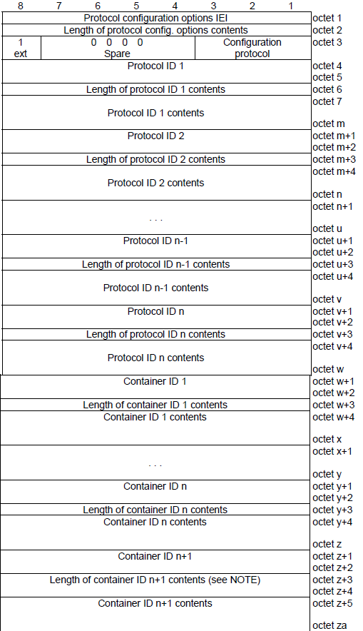
Figure 1. The IE is a list of length-tagged entries rather than a fixed set of fields. That is what lets a new configuration parameter be added without changing the specification of the message carrying it.
Protocol ID entries carry PPP style protocols : IPCP and its options are carried here, which is how IPv4 DNS server addresses reach the UE.Container ID entries carry 3GPP defined parameters : a DNS server IPv6 address request and an IPv4 link MTU request are container IDs rather than protocol IDs.Every entry is length tagged : a decoder can skip an identifier it does not recognise, so an unknown entry costs nothing.The extended form differs only in size : 24.501 uses the extended IE so the contents field can exceed 253 octets, and the internal structure is identical.
GPRS Timer
The GPRS timer is used in various cellular network procedures, such as the PDU (Protocol Data Unit) Establishment process, to manage and control the duration of specific events or actions.
GPRS Timer IEI
Timer Value
Unit
value is incremented in multiples of 2 seconds
value is incremented in multiples of 1 minute
value is incremented in multiples of decihours
value indicates that the timer is deactivated.
- Timer Value: This represents the actual duration of the timer.
- Unit: This indicates the unit of time (e.g., seconds, minutes, decihours) used to interpret the timer value.
If the timer value indicates that the timer is deactivated, it means that the specific event or action associated with the timer is not active or applicable in the current context.
The unit field is what makes this IE compact. A timer value is only five bits, so the range comes from the unit rather than from the number. Multiples of two seconds cover short retries and multiples of a minute cover ordinary back-off. Decihours cover the long periods a network uses to keep a rejected UE away. The deactivated coding is the one to check carefully, because it does not mean zero. It means the timer does not run at all.
The unit carries the range, not the value : a five bit number with a selectable unit covers seconds to hours without a wider field.Deactivated is not the same as expired immediately : the coding switches the timer off, so nothing happens rather than happening at once.The same encoding appears in several places : the RQ timer in the establishment accept and the back-off timer in a DL NAS Transport both use it.
Mapped EPS bearer contexts
"Mapped EPS bearer contexts" indicates the mapping of existing EPS (Evolved Packet System) bearers from a 4G LTE network to 5G PDU sessions when a UE transitions from the 4G network to the 5G network. This mapping ensures that the ongoing data sessions and services are seamlessly continued during the network transition.
During the PDU Session Establishment process in a 5G network, the UE and the network may include the "Mapped EPS bearer contexts" information in the PDU Session Establishment Request and PDU Session Establishment Accept messages, respectively. This information indicates which EPS bearer contexts from the 4G LTE network are being mapped to the new 5G PDU session and the corresponding QoS flow identifiers.
Length of Mapped EPS bearer contexts contents
Mapped EPS bearer context 1
EPS bearer identity
Length of Mapped EPS bearer context
Number of EPS parameters
Ebit
Operation code
EPS parameters list
EPS parmeter identifier 1
Length of EPS parameter contents 1
EPS parameter contents 1
EPS parmeter identifier 2
Length of EPS parameter contents 2
EPS parameter contents 2
...
EPS parmeter identifier n
Length of EPS parameter contents n
EPS parameter contents n
Mapped EPS bearer context 2
EPS bearer identity
Length of Mapped EPS bearer context
Number of EPS parameters
Ebit
Operation code
EPS parameters list
EPS parmeter identifier 1
Length of EPS parameter contents 1
EPS parameter contents 1
EPS parmeter identifier 2
Length of EPS parameter contents 2
EPS parameter contents 2
...
EPS parmeter identifier n
Length of EPS parameter contents n
EPS parameter contents n
...
Mapped EPS bearer context N
EPS bearer identity
Length of Mapped EPS bearer context
Number of EPS parameters
Ebit
Operation code
EPS parameters list
EPS parmeter identifier 1
Length of EPS parameter contents 1
EPS parameter contents 1
EPS parmeter identifier 2
Length of EPS parameter contents 2
EPS parameter contents 2
...
EPS parmeter identifier n
Length of EPS parameter contents n
EPS parameter contents n
PDU address (24.501 - 9.11.4.10)
This is the IE the whole procedure exists to deliver. Everything else negotiates how the session behaves. This one gives the UE the address it will actually use. One detail surprises readers looking at a log for the first time. For IPv6 the network does not send a full address here. It sends an interface identifier, and the UE builds its link local address from that and learns the global prefix later by router advertisement.
PDU address IEI
PDU session type value
IPv4
IPv6
IPv4v6
PDU address information
IPv4 Address (4 Byte)
IPv6 Address (8 Byte)
IPv4v6 Address (12 Byte)
IPv4 is four octets, IPv6 is eight : the eight octets are an interface identifier rather than a 128 bit address, which is why the field looks short.IPv4v6 carries twelve octets : the IPv6 interface identifier comes first and the IPv4 address follows it.The prefix arrives outside NAS : for IPv6 the global prefix reaches the UE by router advertisement on the user plane, not in this IE.
The IE is absent more often than a reader expects. It is optional in the accept, and the network omits it whenever the address is not assigned during establishment. A session using DHCP for IPv4 is the common case, and there the UE gets its address on the user plane after the session is already up.
PDU session type
"PDU session type" indicates the type of data traffic that will be transmitted over the PDU session between UE and the 5G Core Network (5GC). The PDU session type determines the characteristics of the PDU session, such as the IP version used for the data traffic and the type of data bearers required.
The PDU session type is negotiated between the UE and the 5GC during the PDU Session Establishment process. The UE indicates its supported PDU session types in the PDU Session Establishment Request message, and the network selects the appropriate PDU session type based on the UE's capabilities, network configuration, and specific use case. Once the PDU session type is agreed upon, the network assigns IP addresses and allocates resources accordingly, enabling the UE to send and receive data over the established PDU session.
IPv4
IPv6
IPv4v6
Unstructured
Ethernet
reserved
Two of the values on that list behave differently from the other three, and it is worth knowing which before reading a log. Unstructured and Ethernet sessions carry no IP layer at all, so no PDU address is assigned for them. A session that shows an Ethernet type and no address is working correctly rather than failing.
IPv4v6 is one session, not two : a single PDU session carries both address families, and the network answers with the type it selected.Unstructured and Ethernet carry no IP address : the PDU address IE is absent for these types, which is normal rather than an error.The selected type can differ from the requested type : the UE states a preference and the SMF decides, so an IPv4v6 request can come back as IPv4 only.
QoS rules
A QoS rule is a packet classifier with a destination attached. The classifier is the packet filter list, and the destination is the QFI naming the QoS flow that matching traffic should use. The UE applies these rules to uplink traffic. The same rules also tell the UE which flow the network intends to use for a given downlink stream.
QoS rule 1
QoS rule identifier
Length of QoS rule
Number of packet filters
DQR bit
0 the QoS rule is not the default QoS rule.
1 the QoS rule is the default QoS rule.
Rule operation code
Reserved
Create new QoS rule
Delete existing QoS rule
Modify existing QoS rule and add packet filters
Modify existing QoS rule and replace all packet filters
Modify existing QoS rule and delete packet filters
Modify existing QoS rule without modifying packet filters
Reserved
Packet filter list
QoS rule precedence
QoS flow identifier (QFI)
QoS rule 2
QoS rule identifier
Length of QoS rule
Number of packet filters
DQR bit
0 the QoS rule is not the default QoS rule.
1 the QoS rule is the default QoS rule.
Rule operation code
Reserved
Create new QoS rule
Delete existing QoS rule
Modify existing QoS rule and add packet filters
Modify existing QoS rule and replace all packet filters
Modify existing QoS rule and delete packet filters
Modify existing QoS rule without modifying packet filters
Reserved
Packet filter list
QoS rule precedence
QoS flow identifier (QFI)
....
Three fields in each rule decide how it is applied rather than what it matches. The rule operation code says whether this rule is being created, deleted or modified, and modification comes in four forms depending on what happens to the packet filters. The DQR bit marks one rule as the default, and that rule catches traffic no other rule matches. The precedence field orders the rest.
Precedence is the field most often misread. It runs from 0 to 255, and a higher value means lower precedence. A rule with precedence 10 is therefore evaluated before a rule with precedence 200. The value 80 is reserved.
The default QoS rule is the fallback : the DQR bit marks it, and a PDU session that has one can always carry traffic no other rule claims.Higher precedence value means evaluated later : the ordering is inverted against the everyday sense of the word, and a misread here sends traffic to the wrong flow.QFI 0 and QRI 0 are never assigned : 24.501 forbids the network from setting either to zero, so a zero in a log is a decode error rather than a valid value.A rule can carry no packet filters : the modify without modifying packet filters operation sets the count to zero, which changes precedence or QFI alone.
Request Type (24.501-9.11.3.47)
This IE does not travel inside the PDU session message at all. It sits in the UL NAS Transport around it, because the AMF needs it before anything is decoded. The value decides whether the AMF routes the request to a new SMF or to the one already holding a session. An error here breaks a handover rather than merely delaying it.
The purpose of the Request type information element is to indicate the type of the 5GSM message.
Request type value
initial request
existing PDU session
initial emergency request
existing emergency PDU session
modification request
reserved
Spare
Request Type IEI
23.502 - 4.3.2.2.1 states
Initial request : the PDU Session Establishment is a request to establish a new PDU SessionExisting PDU Session : the request refers to an existing PDU Session switching between 3GPP access and non-3GPP access or to a PDU Session handover from an existing PDN connection in EPC. If the request refers to an existing PDN connection in EPC, the S-NSSAI is set as described in 23.501 - 5.15.7.2(initial) emergency request : When Emergency service is required and an Emergency PDU Session is not already established, a UE shall initiate the UE Requested PDU Session Establishment procedure with a Request Type indicating "(initial) Emergency Request".existing emergency PDU session : the request refers to an existing PDU Session for Emergency services switching between 3GPP access and non-3GPP access or to a PDU Session handover from an existing PDN connection for Emergency services
Only initial request creates a session : the other values all refer to something that already exists, whether in 5GS or in EPC.Existing PDU session signals a move : it covers switching between 3GPP and non-3GPP access, and handover from a PDN connection in EPC.The emergency values bypass normal admission : an emergency request is accepted under conditions that would reject an ordinary one.
Session-AMBR (Aggregate Maximum Bit Rate) - (24.501-9.11.4.14)
This is the ceiling for the whole PDU session rather than for any one flow, and it applies only to non-GBR traffic. The IE is eight octets and it carries two independent figures, one for downlink and one for uplink. Each figure is a two octet number with its own unit octet in front of it. That is how a sixteen bit value covers everything from 1 Kbps to 256 Pbps.
Session-AMBR IEI
value is not used
value is incremented in multiples of 1 Kbps
value is incremented in multiples of 4 Kbps
value is incremented in multiples of 16 Kbps
value is incremented in multiples of 64 Kbps
value is incremented in multiples of 256 kbps
value is incremented in multiples of 1 Mbps
value is incremented in multiples of 4 Mbps
value is incremented in multiples of 16 Mbps
value is incremented in multiples of 64 Mbps
value is incremented in multiples of 256 Mbps
value is incremented in multiples of 1 Gbps
value is incremented in multiples of 4 Gbps
value is incremented in multiples of 16 Gbps
value is incremented in multiples of 64 Gbps
value is incremented in multiples of 256 Gbps
value is incremented in multiples of 1 Tbps
value is incremented in multiples of 4 Tbps
value is incremented in multiples of 16 Tbps
value is incremented in multiples of 64 Tbps
value is incremented in multiples of 256 Tbps
value is incremented in multiples of 1 Pbps
value is incremented in multiples of 4 Pbps
value is incremented in multiples of 16 Pbps
value is incremented in multiples of 64 Pbps
value is incremented in multiples of 256 Pbps
Length of Session-AMBR contents
Unit for Session-AMBR for downlink
Session-AMBR for downlink
Unit for Session-AMBR for uplink
Session-AMBR for uplink
SM PDU DN request container
This IE exists for one job, and it is the job the EAP message IE finishes. A data network may run its own authentication in addition to the 5G one. The UE then has to identify itself to that network rather than to the operator. This container carries that identity, and the UE includes it only when establishing a new non-emergency session with such a network.
DN-specific identity : network access identifier (NAI) format according to IETF RFC 7542
The identity here is not the SUPI : it names the UE to the data network behind the session, and the operator identity is irrelevant to that exchange.NAI format is inherited from IETF : the encoding follows RFC 7542, so it looks like a user at realm string rather than a 3GPP identifier.It starts an exchange the EAP message IE continues : the container opens secondary authentication and the EAP message IE carries the rounds that follow.
The IE is 3 to 255 octets, and its size is the reason it is optional. A network access identifier is a string rather than a coded value, so including it costs real space in a message that is otherwise compact. A UE that has no data network credentials leaves it out entirely.
S-NSSAI
A slice identifier is two numbers, and the second one is optional. The SST says what kind of slice this is, using values that are standardised so that an eMBB slice means the same thing in every network. The SD distinguishes several slices of the same kind inside one operator, and it carries no meaning outside that operator.
S-NSSAI IEI
Length of S-NSSAI contents
SST
SST and mapped HPLMN SST
SST and SD
SST, SD and mapped HPLMN SST
SST, SD, mapped HPLMN SST and mapped HPLMN SD
SST(Slice/service type)
SD(Slice differentiator)
Mapped HPLMN SST
Mapped HPLMN SD
SST is standardised, SD is not : the same SST value means the same service type everywhere, while an SD is meaningful only within the operator that assigned it.The mapped HPLMN fields exist for roaming : they carry the home network's identifier for the same slice, so a visited network can map its own S-NSSAI onto it.Length tells you which form is present : the IE runs from 3 to 10 octets, and the length alone says whether SD and the mapped values are included.
One point about scope is easy to miss. The S-NSSAI in a PDU session message identifies the slice this one session belongs to. It has to be one of the S-NSSAIs the AMF already allowed during registration. A session cannot introduce a slice the UE was never granted.
SSC (Session and Service Continuity) mode
SSC (Session and Service Continuity) modes refer to different ways of handling mobility and data flow during a PDU session when the User Equipment (UE) moves between different access networks or between 4G and 5G networks.
SSC mode 1
SSC mode 2
SSC mode 3
unused; shall be interpreted as "SSC mode 1", if received by the network
unused; shall be interpreted as "SSC mode 2", if received by the network
unused; shall be interpreted as "SSC mode 3", if received by the network
SSC Mode 1 : In this mode, the PDU session is anchored at the User Plane Function (UPF) in the 5G Core Network (5GC). When the UE moves between different access networks or between 4G and 5G networks, the data path is switched at the UPF. The UE maintains a single PDU session, and the data flow is continuous during the handover process. This mode provides seamless session and service continuity.SSC Mode 2 : In this mode, the UE establishes separate PDU sessions for different access networks or for 4G and 5G networks. When the UE moves between networks, the data flow is switched between the different PDU sessions at the UE. This mode does not provide seamless session and service continuity, as the UE needs to establish a new PDU session when moving to a different network, which may cause temporary disruption in the data flow.SSC Mode 3 : This mode is a combination of SSC Mode 1 and SSC Mode 2. The UE establishes separate PDU sessions for different access networks or for 4G and 5G networks, similar to SSC Mode 2. However, the data flow is switched at the UPF, like in SSC Mode 1, providing seamless session and service continuity. This mode is used when the UE moves between networks with different PDU session types, such as from a 5G non-roaming network to a 4G roaming network.
Payload container type (24.501-9.11.3.40)
The purpose of the Payload container type information element indicates type of payload included in the payload container information element. This type can be one of the followings :
N1 SM information
SMS
LTE Positioning Protocol (LPP) message container
SOR transparent container
UE policy container
UE parameters update transparent container
Location services message container
CIoT user data container
Multiple payloads
Only the first value on that list belongs to PDU session signalling. N1 SM information is what a PDU Session Establishment Request travels as, and everything else on the list is a different service reusing the same transport. SMS, LPP and the UE policy container all use the same UL and DL NAS Transport messages. That is why a capture filtered on those message types also shows traffic unrelated to PDU sessions.
One transport, many passengers : the payload container type is the only field separating a PDU session procedure from an SMS or a positioning message.Multiple payloads is a container of containers : that value lets one NAS Transport carry several payloads, each with its own type.
The Multiple payloads coding needs care, because it changes how the container itself is parsed. The contents then begin with a number of entries field, and each entry carries its own type and its own length. A decoder that assumes a single payload will read the entry count as message data.
MA PDU session information (24.501 - 9.11.3.31A)
Multi-access is the one case where a PDU session is not tied to a single access network. The ATSSS feature lets one session hold user plane resources on a 3GPP access and a non-3GPP access at the same time, and steer traffic between them. This IE is how that intent is signalled during establishment.
The IE is a type 1 element, so it occupies half an octet and carries a single meaningful value. That value says the network is allowed to upgrade the session to multi-access. It is permission rather than instruction, and the upgrade itself happens later through PDU session modification.
An MA PDU session spans two access networks at once : 3GPP and non-3GPP user plane resources coexist under one session, which is what ATSSS steers across.This IE grants permission, it does not perform the upgrade : the network acts on it afterwards, and the ATSSS rules themselves arrive in a modification procedure.Half an octet is the whole IE : it is a type 1 element, so it costs nothing to include and is easy to miss in a decode.
The purpose of the MA PDU(Multi Access PDU) session information information element is to convey the MA-related information for the PDU session.
Currently there is only one value specified for this IE
MA PDU session network upgrade is allowed
Reference
The message contents, the IE codings and the timer values on this page were taken from the 3GPP documents listed first, and checked field by field against them. The other entries were the background reading behind the descriptive sections.
- 24.501 : Non-Access-Stratum (NAS) protocol for 5G System (5GS). Source for the message content tables in clause 8.3, every IE coding in clause 9.11, the UE-requested PDU session establishment procedure in clause 6.4.1, and the T3580 timer table. The version read was v20.0.0 (Release 20).
- 24.008 : Mobile radio interface Layer 3 specification - Core network protocols. Source for the protocol configuration options structure in clause 10.5.6.3, which 24.501 reuses unchanged.
- 23.502 : Procedures for the 5G System. Source for the Request Type descriptions quoted in this note.
- 23.501 : System architecture for the 5G System. Named by 24.501 for the SSC mode definitions and the packet filter component combinations. Not read directly for this note.
- Protocol Data Unit RAN Tunnel Endpoint Identifier Session - Cisco
- Session and Service Continuity Mode - Cisco
- SSC Modes Session and Service Continuity in 5G - Techplayon
- Session and Service Continuity Evolution in 5G Networks - 4G 5G World
- Handling QoS Flow Description and EPS Bearer Operation Errors in 4G 5G Systems - Patent 16/792453
- 3GPP SA2 architecture and functions for 5G mobile communication system
- 5G beyond radio access: a flatter sliced network
- End to End Network Slicing
YouTube
- 5G Session Management Signalling Analysis - Taha Sajid - (2021)
- 5G Core - PDU session establishment procedure - Raghevendra Agarwal (2022)
- PDU Session Establishment - Part of 5G Course (Link in Description) - itelcotech (2023)