A band combination is the answer to one question: which carriers may a UE aggregate at the same time. The question has two halves, and this page keeps them apart. One half is what 3GPP allows, and the other is what a particular handset reports.
Both halves meet in the same RRC message. UE Capability Information carries the list a UE supports, and 36.101 carries the list that exists to be supported. Everything below is one side or the other of that pairing.
- Band Combination Definition
- CA Bandwidth Class Definition
- How to figure out BandCombination and Bandwidth Class supported by a UE ?
- BandCombination and BandwidthClass defined by 3GPP
- What the band combination list became
- Reference
Band Combination Definition
The most important thing you have to pay attention in UE Capability Information is CA Band combination as specified in RRC message as shown below. A band combination is not a single field. It is one entry of a list, and each entry is itself a list of bands with a bandwidth class attached to each of them.
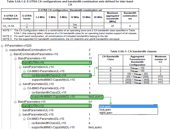
One row of 36.101 on the left, and the same information as a UE reports it on the right. The green marks join the two, field by field.
The left hand table names the combination : CA_1A-5A is band 1 with class A beside band 5 with class A, and the row gives its maximum aggregated bandwidth as 20 MHz.The tree carries the same thing as numbers : bandEUTRA-r10 reads 1 and then 5, and ca-BandwidthClassUL-r10 and ca-BandwidthClassDL-r10 both read a.MIMO capability is per band, not per combination : supportedMIMO-CapabilityDL-r10 sits inside each band's own CA-MIMO-ParametersDL-r10, and the drop-down beside it offers twoLayers, fourLayers and eightLayers.An uplink entry is optional : the second band in the tree has a bandParametersDL-r10 and no bandParametersUL-r10, which is how a UE says the band is downlink only in this combination.
Following is the example for Band combination of a 3CC Carrier Aggregation.
UE Capability Information for a UE reporting fifteen band combinations, decoded as a tree,
nonCriticalExtension
    ue-Category-v1020: 6
    rf-Parameters-v1020
        supportedBandCombination-r10: 15 items
            Item 0
                BandCombinationParameters-r10: 3 items
                    Item 0
                        BandParameters-r10
                            bandEUTRA-r10: 1
                            bandParametersUL-r10: 1 item
                                Item 0
                                    CA-MIMO-ParametersUL-r10
                                        ca-BandwidthClassUL-r10: a (0)
                            bandParametersDL-r10: 1 item
                                Item 0
                                    CA-MIMO-ParametersDL-r10
                                        ca-BandwidthClassDL-r10: a (0)
                                        supportedMIMO-CapabilityDL-r10: twoLayers (0)
                    Item 1
                        BandParameters-r10
                            bandEUTRA-r10: 5
                            bandParametersDL-r10: 1 item
                                Item 0
                                    CA-MIMO-ParametersDL-r10
                                        ca-BandwidthClassDL-r10: a (0)
                                        supportedMIMO-CapabilityDL-r10: twoLayers (0)
                    Item 2
                        BandParameters-r10
                            bandEUTRA-r10: 7
                            bandParametersDL-r10: 1 item
                                Item 0
                                    CA-MIMO-ParametersDL-r10
                                        ca-BandwidthClassDL-r10: a (0)
                                        supportedMIMO-CapabilityDL-r10: twoLayers (0)
Three numbers in that capture are worth reading together. supportedBandCombination-r10 holds 15 items, so this UE reports fifteen different combinations. Item 0 holds three BandParameters-r10, which is what makes it a three carrier combination. Only the first of the three carries a bandParametersUL-r10.
That last point is the shape of almost every combination on this page. The downlink aggregates three bands and the uplink stays on one, because uplink aggregation needs more power from the handset and a second transmit chain.
The list length has a bound, and 36.331 gives it a name. SupportedBandCombination-r10 is SIZE (1..maxBandComb-r10), and maxBandComb-r10 is 128. Each entry is itself SIZE (1..maxSimultaneousBands-r10) of BandParameters-r10, and maxSimultaneousBands-r10 is 64.
Fifteen combinations in this capture : supportedBandCombination-r10 reads 15 items, and each item is one combination.Three bands make a three carrier combination : Item 0 holds three BandParameters-r10 entries, for bands 1, 5 and 7.Only band 1 carries an uplink : the other two have a bandParametersDL-r10 and nothing else.128 combinations is the Release 10 ceiling : 36.331 defines maxBandComb-r10 as 128 and maxSimultaneousBands-r10 as 64.
Another important part is featureGroupIndicator (FGI) for r10. It has following items.
UE Capability Information, the featureGroupIndRel10-r10 bit string with every bit named,
     featureGroupIndRel10-r10: 00000000 [bit length 32, 0000 0000  0000 0000  0000 0000  0000 0000 decimal value 0]
         0... .... = Indicator 101: DMRS with OCC (orthogonal cover code) and SGH (sequence group hopping) disabling - Not supported
         .0.. .... = Indicator 102: Trigger type 1 SRS (aperiodic SRS) transmission (Up to X ports) - Not supported
         ..0. .... = Indicator 103: PDSCH TM9 when up to 4 CSI reference signal ports are configured - Not supported
         ...0 .... = Indicator 104: PDSCH TM9 for TDD when 8 CSI reference signal ports are configured - Not supported
         .... 0... = Indicator 105: PUCCH RM2-0 when PDSCH TM9 is configured and RM2-1 when PDSCH TM9
                                    and up to 4 CSI reference signal ports are configured - Not supported
         .... .0.. = Indicator 106: PUCCH RM2-1 when PDSCH TM9 and 8 CSI reference signal ports are configured - Not supported
         .... ..0. = Indicator 107: PUSCH RM2-0 when PDSCH TM9 is configured and RM2-2 when PDSCH TM9 and
                                    up to 4 CSI reference signal ports are configured - Not supported
         .... ...0 = Indicator 108: PUSCH RM2-2 when PDSCH TM9 and 8 CSI reference signal ports are configured - Not supported
         0... .... = Indicator 109: PUCCH RM1-1 submode 1 - Not supported
         .0.. .... = Indicator 110: PUCCH RM1-1 submode 2 - Not supported
         ..0. .... = Indicator 111: Measurement reporting trigger Event A6 - Not supported
         ...0 .... = Indicator 112: SCell addition within the Handover to EUTRA procedure - Not supported
         .... 0... = Indicator 113: Trigger type 0 SRS (periodic SRS) transmission on X Serving Cells - Not supported
         .... .0.. = Indicator 114: Reporting of both UTRA CPICH RSCP and Ec/N0 in a Measurement Report - Not supported
         .... ..0. = Indicator 115: Time domain ICIC RLM/RRM / ICIC RRM / ICIC CSI measurement sf restriction
                                    for the serving cell / neighbour cells - Not supported
         .... ...0 = Indicator 116: Relative transmit phase continuity for spatial multiplexing in UL - Not supported
CA Bandwidth Class Definition
Following table shows Carrier Aggregation Bandwidth Class in terms of total number of RBs used by aggregated carrier. The class bounds the total rather than naming the carriers, so two very different aggregates can share one class and one modest looking pair can exceed it.
For example, CA Bandwidth Class 'B' says N_RB,agg <= 100. It means that total aggregated RB should be less than 100. Following shows some example cases which is allowed and not allowed configuration.
Case 1 : PCC = 10 Mhz (max 50 RB), SCC = 10 Mhz (max 50 RB).
It would give max aggregated RB is 50 RB +50 RB which is <= 100. So this is allowed.
Case 2 : PCC = 10 Mhz (max 50 RB), SCC = 15 Mhz (max 75 RB).
It would give max aggregated RB is 50 RB +75 RB which is >= 100. So this is not allowed.
36.101(Rel 13) - Table 5.6A-1: CA bandwidth classes and corresponding nominal guard bands

A is the single carrier row : N RB,agg of 100 or fewer on one contiguous component carrier, which is an ordinary cell rather than an aggregate.B and C differ only in range : both take two contiguous carriers, and the split is at 100 resource blocks.The carrier count rises with the class : class D takes three, class E four, class F five and class I eight.The table skips two letters : the classes run A, B, C, D, E, F and then jump to class I.The RRC enumeration never followed : CA-BandwidthClass-r10 in 36.331 v19.3.0 still lists only a to f, so class I is reached through the extension marker rather than a named value.
This bandwidth class supported by a UE is reported to network via UE Capability Information message as shown below.
Following is the example for 2CC Carrier Aggregation supportability : DL 4A_17A, UL 4A
UE Capability Information for DL 4A_17A and UL 4A, decoded as a tree,
nonCriticalExtension
    rf-Parameters-v1020
        supportedBandCombination-r10: 1 item
            Item 0
                BandCombinationParameters-r10: 2 items
                    Item 0
                        BandParameters-r10
                            bandEUTRA-r10: 4
                            bandParametersUL-r10: 1 item
                                Item 0
                                    CA-MIMO-ParametersUL-r10
                                        ca-BandwidthClassUL-r10: a
                            bandParametersDL-r10: 1 item
                                Item 0
                                    CA-MIMO-ParametersDL-r10
                                        ca-BandwidthClassDL-r10: a
                                        supportedMIMO-CapabilityDL-r10: twoLayers
                    Item 1
                        BandParameters-r10
                            bandEUTRA-r10: 17
                            bandParametersDL-r10: 1 item
                                Item 0
                                    CA-MIMO-ParametersDL-r10
                                        ca-BandwidthClassDL-r10: a
                                        supportedMIMO-CapabilityDL-r10: twoLayers
Following is the example for Band class of a 3CC Carrier Aggregation : DL 1A_5A_7A, UL 1A
UE Capability Information for DL 1A_5A_7A and UL 1A, decoded as a tree,
nonCriticalExtension
    ue-Category-v1020: 6
    rf-Parameters-v1020
        supportedBandCombination-r10: 15 items
            Item 0
                BandCombinationParameters-r10: 3 items
                    Item 0
                        BandParameters-r10
                            bandEUTRA-r10: 1
                            bandParametersUL-r10: 1 item
                                Item 0
                                    CA-MIMO-ParametersUL-r10
                                        ca-BandwidthClassUL-r10: a (0)
                            bandParametersDL-r10: 1 item
                                Item 0
                                    CA-MIMO-ParametersDL-r10
                                        ca-BandwidthClassDL-r10: a (0)
                                        supportedMIMO-CapabilityDL-r10: twoLayers (0)
                    Item 1
                        BandParameters-r10
                            bandEUTRA-r10: 5
                            bandParametersDL-r10: 1 item
                                Item 0
                                    CA-MIMO-ParametersDL-r10
                                        ca-BandwidthClassDL-r10: a (0)
                                        supportedMIMO-CapabilityDL-r10: twoLayers (0)
                    Item 2
                        BandParameters-r10
                            bandEUTRA-r10: 7
                            bandParametersDL-r10: 1 item
                                Item 0
                                    CA-MIMO-ParametersDL-r10
                                        ca-BandwidthClassDL-r10: a (0)
                                        supportedMIMO-CapabilityDL-r10: twoLayers (0)
Followings are some more examples without the detailed RRC message.
- CA_46C-48E : This is 6CC CA because the class 'C' supports 2CC contiguous band and the class 'D' support 4CC configuous band.
- CA_2A-46A-48E : This is 6CC CA because there are two class 'A' band which support 1 CC for each band and one class 'E' that support 4 CC contiguous band.
- CA_2A-46C-48E : This is 7CC CA because there is one class 'A' which support 1CC, one class 'C' which support 2CC contiguous and one class 'E' that support 4CC contiguous bands.
The three worked examples above the tables read a class name as a carrier count, and that reading is the useful one. A letter says how many contiguous carriers one band contributes, so adding the letters across a combination gives the carrier total.
The class is a bound on resource blocks : 36.101 Table 5.6A-1 sets an aggregated transmission bandwidth range for each letter.It also fixes a carrier count : which is what the CA_46C-48E style examples above use it for.A UE reports one class per band per direction : ca-BandwidthClassUL-r10 and ca-BandwidthClassDL-r10 sit in separate structures.
How to figure out BandCombination and Bandwidth Class supported by a UE ?
Now the question you may ask is how can I know which band combination of bands a UE support in terms of Carrier Aggregation ? The answer is one field in one message, and the difficulty is its size rather than its shape. The list it belongs to may hold hundreds of entries.
It is also supposed to be reported to network by the UE via UE Capability Information message. Followings are some of the possible IEs a UE may use depending on its release status.
Following is based on
RF-Parameters-v1020 ::= SEQUENCE {
    supportedBandCombination-r10 SupportedBandCombination-r10
}

RF-Parameters-v1090 ::= SEQUENCE {
    supportedBandCombination-v1090 SupportedBandCombination-v1090 OPTIONAL
}

RF-Parameters-v1130 ::= SEQUENCE {
    supportedBandCombination-v1130 SupportedBandCombination-v1130 OPTIONAL
}
All three are unchanged in 36.331 v19.3.0, down to the OPTIONAL on the later two. Each one carries a list of band combinations, and the three lists are read together rather than as alternatives.
The definition of these IE is described as below in 36.331. Generally it sounds OK.. but it is not very clear to me if I go into one step deeper. For example, this definition does not clearly explain on which item in the list can be a PCC (Primary Component Carrier) and which should be SCC (Secondary Component Carrier). As far as I know, there is no priority of these items in terms of determining PCC/SCC, meaning either one should be allowed to be PCC depending on situation. But you may see some UE that allows only specific PCC/SCC mapping.
bandCombinationListEUTRA : One entry corresponding to each supported band combination listed in the same order as in supportedBandCombination.
BandCombinationParameters-v1090 : If included, the UE shall include the same number of entries, and listed in the same order, as in BandCombinationParameters-r10.
BandCombinationParameters-v1130 :The field is applicable to each supported CA bandwidth class combination (i.e. CA configuration in TS 36.101 Section 5.6A.1 indicated in the corresponding band combination
One example of Carrier Combination information in UE Capability Information is as follows. This example shows the UE allows Carrier Aggregation between band 4 and band 17.
The same rf-Parameters-v1020 branch again,
nonCriticalExtension
    rf-Parameters-v1020
        supportedBandCombination-r10: 1 item
            Item 0
                BandCombinationParameters-r10: 2 items
                    Item 0
                        BandParameters-r10
                            bandEUTRA-r10: 4
                            bandParametersUL-r10: 1 item
                                Item 0
                                    CA-MIMO-ParametersUL-r10
                                        ca-BandwidthClassUL-r10: a
                            bandParametersDL-r10: 1 item
                                Item 0
                                    CA-MIMO-ParametersDL-r10
                                        ca-BandwidthClassDL-r10: a
                                        supportedMIMO-CapabilityDL-r10: twoLayers
                    Item 1
                        BandParameters-r10
                            bandEUTRA-r10: 17
                            bandParametersDL-r10: 1 item
                                Item 0
                                    CA-MIMO-ParametersDL-r10
                                        ca-BandwidthClassDL-r10: a
                                        supportedMIMO-CapabilityDL-r10: twoLayers
The three structures above are read together rather than chosen between. A UE fills in as many of them as its release supports, and a network that understands only the first reads only the first.
One field answers the question : supportedBandCombination-r10 inside rf-Parameters-v1020 holds every combination the UE supports.Two later fields extend it : supportedBandCombination-v1090 and -v1130 add to the same list rather than replacing it, and both are OPTIONAL.Order is the link between them : 36.331 requires the later lists to hold the same number of entries in the same order as the first.An entry is a list of bands : each one carries a bandEUTRA-r10 and a bandwidth class per direction, as the capture above shows.
BandCombination and BandwidthClass defined by 3GPP
Following Table from 36.101 V12.5.0 (2014-11) shows all the possible (allowed) band combination of inter-band CA case. This list is likely to get extended as time goes on. So try to refer to latest spec.
When you want to analyze UE capability, you can refer to bandEUTRA-r10 and ca-BandwidthClassDL-r10 in a BandCombinationParameters to figure out complete CA configuration as expressed in the first column of following tables.
The version stamp in the sentence above covers only part of what follows. Tables 5.6A.1-1 and 5.6A.1-2 below are the v12.5.0 copies that sentence names, but the heading above Table 5.6A.1-2a says v13.3.0 and the one above Table 5.6A.1-2b says v13.2.1. The three band table in particular is a later capture than the sentence suggests, and the extra column below is the evidence.
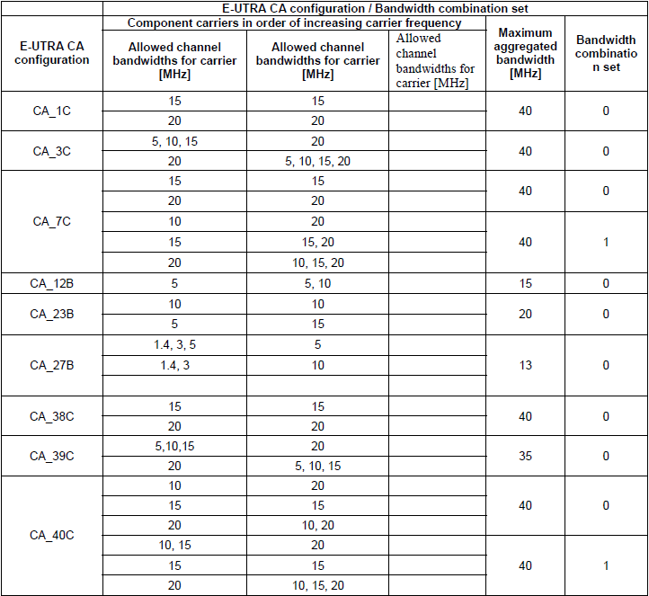
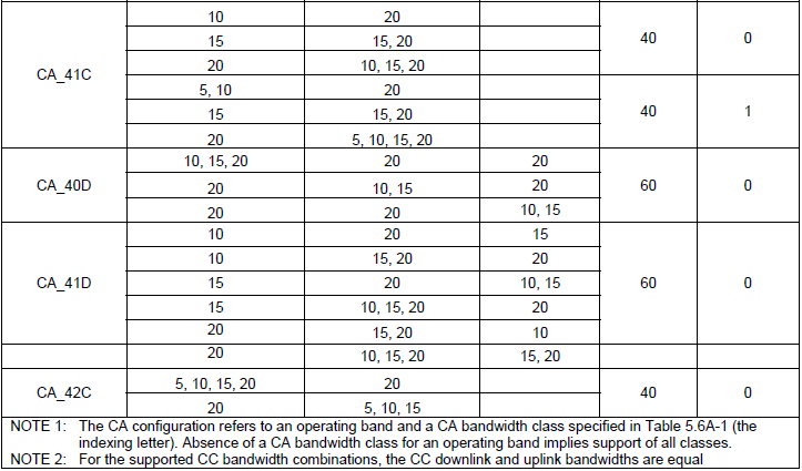
- 36.101 Table 5.6A.1-1: E-UTRA CA configurations and bandwidth combination sets defined for intra-band contiguous CA
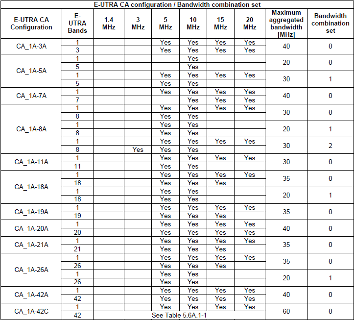
- 36.101 Table 5.6A.1-2: E-UTRA CA configurations and bandwidth combination sets defined for inter-band CA (two bands)
- 36.101 Table 5.6A.1-2a: E-UTRA CA configurations and bandwidth combination sets defined for inter-band CA (three bands)
- 36.101 v13.2.1 Table 5.6A.1-2b: E-UTRA CA configurations and bandwidth combination sets defined for inter-band CA (four bands)
< 36.101 Table 5.6A.1-1: E-UTRA CA configurations and bandwidth combination sets defined for intra-band contiguous CA >
< 36.101 Table 5.6A.1-2: E-UTRA CA configurations and bandwidth combination sets defined for inter-band CA >
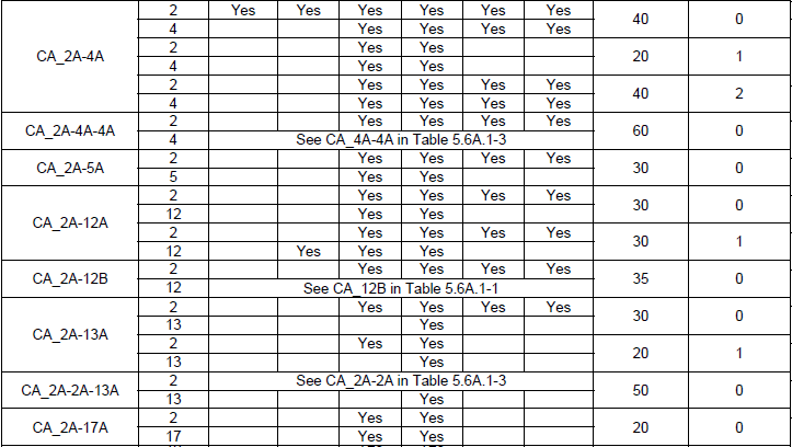
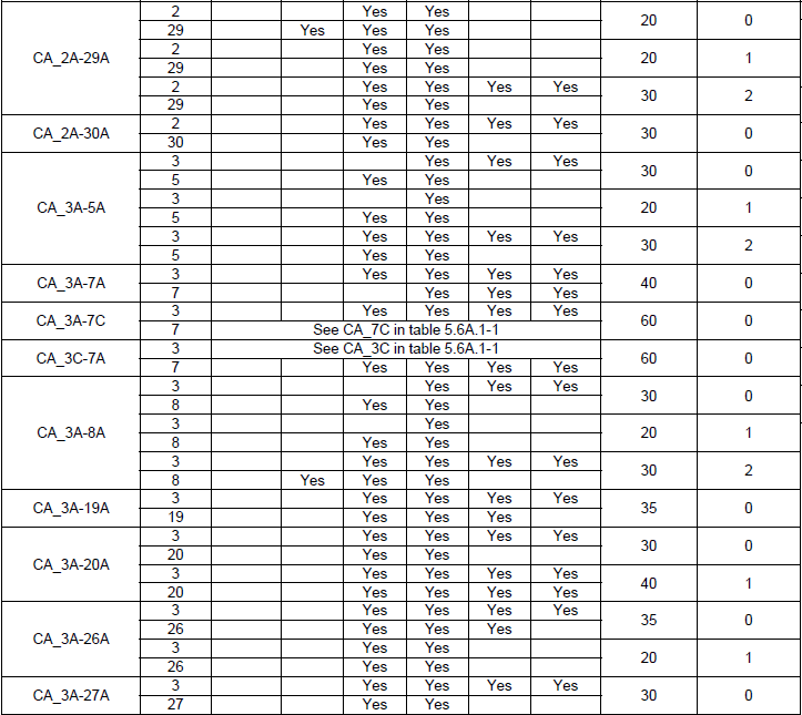
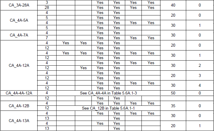
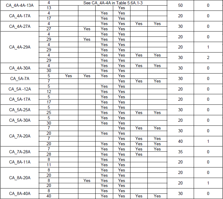
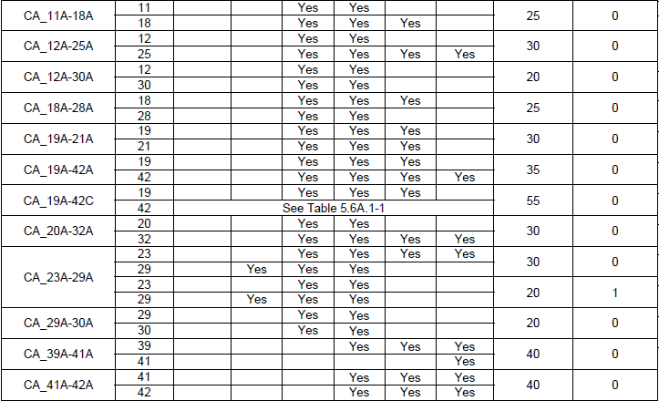
< 36.101-V13.3.0 Table 5.6A.1-2a: E-UTRA CA configurations and bandwidth combination sets defined for inter-band CA (three bands) >
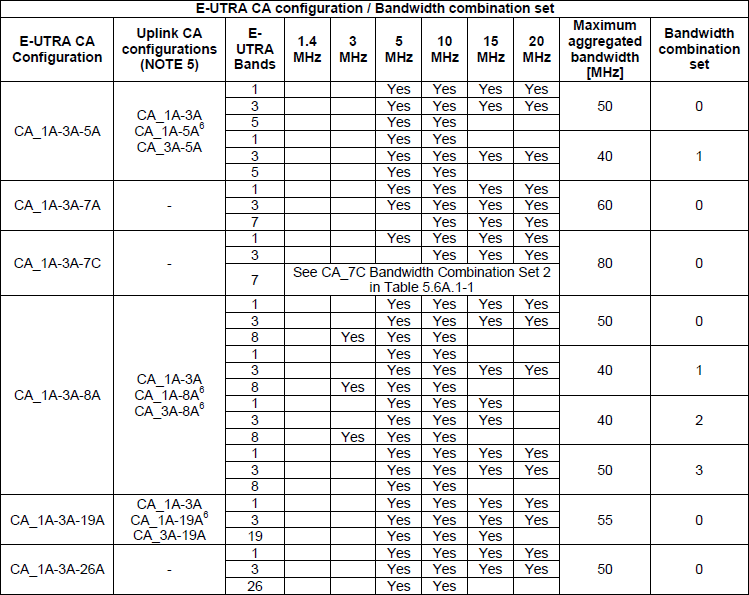
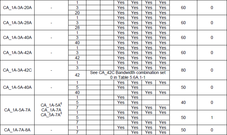
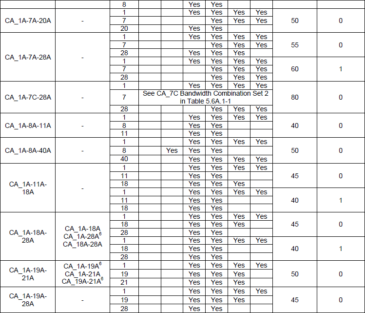
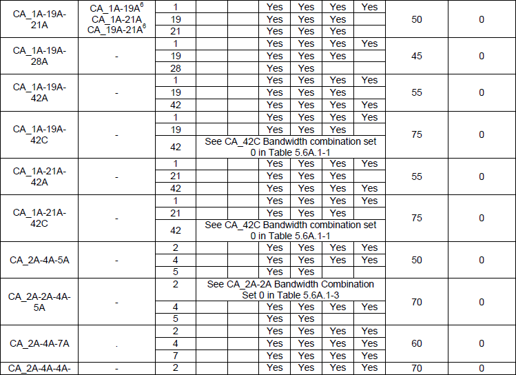
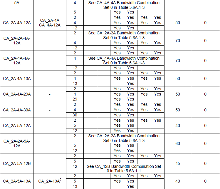
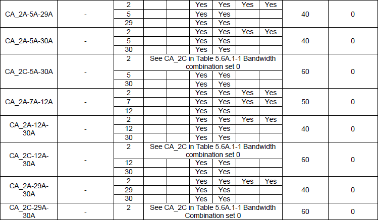
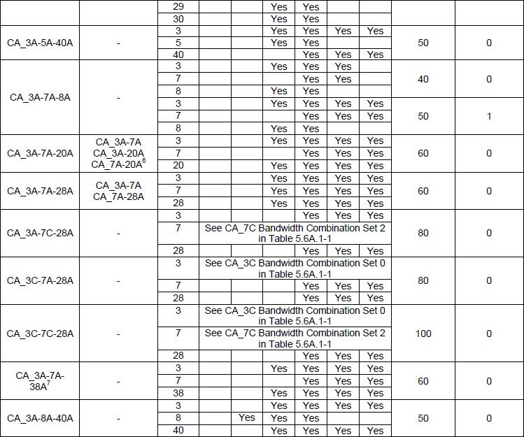
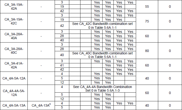
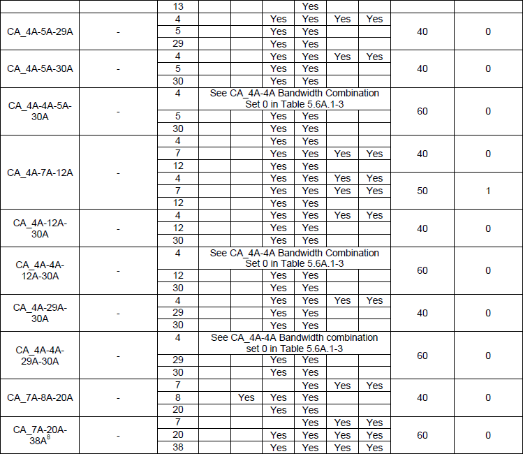

The three band table as Release 13 left it. The second column is the one the earlier copies of this table do not have, and most of its cells hold a dash.
Release 13 added an uplink column : the heading reads Uplink CA configurations and refers to NOTE 5, and the v12.5.0 copy of the same table has no such column.A dash means no uplink aggregation : most rows read a single dash there, so the downlink aggregates three bands while the uplink stays on one.Where an uplink is listed it is shorter : CA_1A-3A-5A names CA_1A-3A, CA_1A-5A and CA_3A-5A, all two band combinations against a three band downlink.Some rows defer to another table : a cell reading See CA_7C Bandwidth Combination Set 2 in Table 5.6A.1-1 sends the reader to the intra-band table for that band's bandwidths.The maximum aggregated bandwidth column is the useful one : it runs from 40 to 100 MHz across these rows, and it is the number a throughput estimate starts from.
Following table is the 4 CC combination defined in 36.101 v13.2.1 Table 5.6A.1-2b: E-UTRA CA configurations and bandwidth combination sets defined for inter-band CA (four bands)
< 36.101 v13.2.1 Table 5.6A.1-2b: E-UTRA CA configurations and bandwidth combination sets defined for inter-band CA (four bands) >
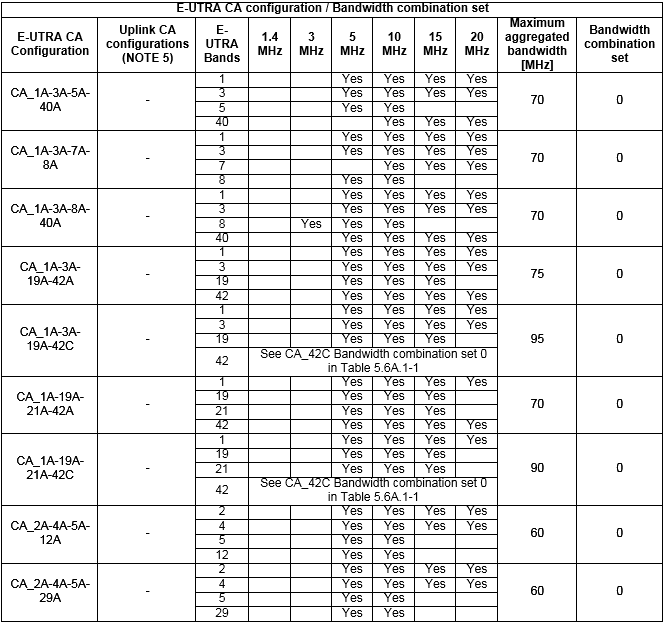
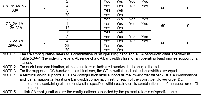
One of the UE capability information that may confuses you would be following IE. This IE shows you which band are supported by the UE in terms of single carrier. It is not about Carrier Aggregation.
UE Capability Information, the rf-Parameters branch listing the bands the UE supports on their own,
rf-Parameters
  supportedBandListEUTRA: 4 items
      Item 0
          SupportedBandEUTRA
              bandEUTRA: 2
              ..0. .... halfDuplex: False
      Item 1
          SupportedBandEUTRA
              bandEUTRA: 4
              .0.. .... halfDuplex: False
      Item 2
          SupportedBandEUTRA
              bandEUTRA: 5
              0... .... halfDuplex: False
      Item 3
          SupportedBandEUTRA
              bandEUTRA: 17
              .... ...0 halfDuplex: False
What the band combination list became
The three structures quoted above answered this question in Release 10 and 11. The answer did not stay that size. By Release 13 the list had grown far enough that the network had to be given a way of asking for less of it.
The list lengths tell the story on their own. SupportedBandCombination-r10 is bounded by maxBandComb-r10, which 36.331 defines as 128. Release 11 added SupportedBandCombinationAdd-r11 with maxBandComb-r11 at 256. Release 13 added SupportedBandCombinationReduced-r13 with maxBandComb-r13 at 384.
Three lists in one message is a lot of signalling, and Release 13 made the exchange a negotiation. RF-Parameters-v1310 carries eNB-RequestedParameters-r13, and the network sends it into the capability enquiry to narrow what comes back.
Following is based on
RF-Parameters-v1310 ::=             SEQUENCE {
    eNB-RequestedParameters-r13         SEQUENCE {
        reducedIntNonContCombRequested-r13  ENUMERATED {true}                       OPTIONAL,
        requestedCCsDL-r13                  INTEGER (2..32)                         OPTIONAL,
        requestedCCsUL-r13                  INTEGER (2..32)                         OPTIONAL,
        skipFallbackCombRequested-r13       ENUMERATED {true}                       OPTIONAL
    }                                                                               OPTIONAL,
    maximumCCsRetrieval-r13                 ENUMERATED {supported}                  OPTIONAL,
    skipFallbackCombinations-r13            ENUMERATED {supported}                  OPTIONAL,
    reducedIntNonContComb-r13               ENUMERATED {supported}                  OPTIONAL,
    supportedBandListEUTRA-v1310            SupportedBandListEUTRA-v1310            OPTIONAL,
    supportedBandCombinationReduced-r13     SupportedBandCombinationReduced-r13     OPTIONAL
}
Every field in the inner SEQUENCE narrows the answer. requestedCCsDL and requestedCCsUL are INTEGER (2..32), and 36.331 describes them as the maximum number of component carriers the network is asking about. A network that supports three carriers has no reason to receive combinations for thirty-two.
skipFallbackCombRequested removes a second group, and the reason it can be removed is printed on the last table screenshot above. NOTE 4 of Table 5.6A.1-2b says a terminal supporting a downlink CA configuration shall support all the lower order fallback downlink CA combinations. Those combinations are implied, so they need not be listed.
reducedIntNonContCombRequested trims a third group, the intra-band non-contiguous combinations. The three outer ENUMERATED fields beside the inner SEQUENCE are the UE saying whether it understands each request at all.
The result is supportedBandCombinationReduced-r13, which 36.331 describes as the supported CA band combinations and which may include the fallback combinations. A Release 13 capability message can therefore carry three combination lists: the original, the additional one from Release 11, and the reduced one.
128, then 256, then 384 : maxBandComb-r10, maxBandComb-r11 and maxBandComb-r13 bound the three combination lists.The network asks for a bounded answer : requestedCCsDL and requestedCCsUL are INTEGER (2..32).Fallback combinations are implied, not listed : 36.101 makes support of the lower order combinations mandatory, so 36.331 lets the network ask for them to be left out.The UE says what it understands : maximumCCsRetrieval, skipFallbackCombinations and reducedIntNonContComb each report whether the matching request is supported.Three lists can travel in one message : the Release 10, Release 11 and Release 13 lists are separate fields.
Reference
Two specifications carry everything quoted on this page. 36.331 defines the fields a UE fills in. 36.101 defines the combinations those fields may name. The third entry is the page on this site that shows the same message in its whole RRC context.
- [1] 36.331 : 3GPP - E-UTRA; Radio Resource Control, v19.3.0. The RF-Parameters family and the maxBandComb constants are quoted above.
- [2] 36.101 : 3GPP - E-UTRA; UE radio transmission and reception. Table 5.6A-1 holds the bandwidth classes and Tables 5.6A.1-1 to 5.6A.1-2b hold the band combinations shown above.
- [3] LTE Advanced RRC : the same capability message in its whole RRC context, with the reconfiguration that acts on it.