This page will review various aspects on LTE Advanced especially with focus on Carrier Aggregation in RRC Messages (Mostly UE Capability Information and RRC Connection Reconfiguration). Everything the network needs to know about a UE's carrier aggregation arrives in one message, and everything it then tells the UE arrives in another. The page is built around that pair.
- RRC Snapshots for LTE Advanced
- Closer view on Carrier Aggregation Establishment - 2CC
- Closer view on Carrier Aggregation Establishment - 3CC
- RRC Message Examples
- The band combination list after Release 11
- Reference
- Get the Test Procedure and Log / Amarisoft TechAcademy
RRC Snapshots for LTE Advanced
There are a good news and a bad news on RRC messages for Carrier Aggregation. Which one do you want to go first ? The two are the same fact seen from either end. The sections below take the good news first, and the rest of the page is about the bad one.
Good News first ?
Good News is that basically there would be only two messages you have to dig into. (UE Capability Information and RRC Connection Reconfiguration).
Now goes the Bad News.
Bad News is that the two message are so complicated (contains so much information), it is extremely difficult to understand all the details. At least to me, it seems to take a couple of YEARS to understand all of those details.
Following is overall steps for LTE adavanced Carrier Aggregation and UE Capability Information and RRC Connection Reconfiguration is the critical steps for Carrier Aggregation configuration.

The two notes on the right mark the only two messages in the whole sequence that carry carrier aggregation. Everything else runs exactly as it does without it.
Capability comes before configuration : UE Capability Enquiry and Information sit above RRC Security, and the Reconfiguration that uses the answer sits below it.The network asks first : the enquiry is drawn from the network to the UE, so a UE never offers its carrier aggregation capability unprompted.Only two arrows are annotated : UE Capability Information reports the capability, and RRC Connection Reconfiguration acts on it.The rest of the call is ordinary : RRC Setup, Authentication, NAS Security and RRC Security are drawn without comment because carrier aggregation changes none of them.
Followings is the information carried by UE Capability Information and its IEs for carrier aggregation and antenna configuration. (These are from 3GPP TS 36.331 version 10.4.0 Release 10)
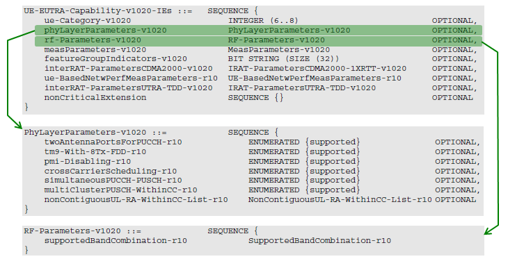
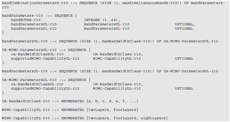
Following table is used to configure 'CA-BandwidthClass-r10' IE (This table is from 3GPP TS 36.101 version 10.8.0 Release 13)
36.101(Rel 13) - Table 5.6A-1: CA bandwidth classes and corresponding nominal guard bands

A is the single carrier row : N RB,agg of 100 or fewer on one contiguous component carrier, which is an ordinary cell rather than an aggregate.B and C differ only in range : both take two contiguous carriers, and the split is at 100 resource blocks.The carrier count rises with the class : class D takes three, class E four, class F five and class I eight.The table skips two letters : the classes run A, B, C, D, E, F and then jump to class I.The guard band is given as a formula : 0.05 times the largest channel bandwidth in the set, less half the subcarrier spacing.
Followings is RRC Connection Reconfiguration message and its IEs for carrier aggregation and antenna configuration. (These are from 3GPP TS 36.331 version 10.4.0 Release 10)
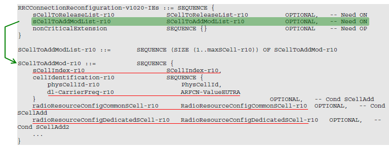
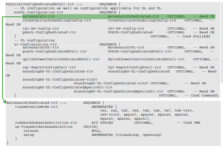
Two of the listings in the pictures above have moved on since they were captured, and both changes are one line each. In AntennaInfoDedicated-r10 the first spare of the transmission mode enumeration is now tm10-v1130, so the list reads tm1 to tm9-v1020, then tm10-v1130, then spare6 down to spare1. In RRCConnectionReconfiguration-v1020-IEs the nonCriticalExtension is no longer an empty SEQUENCE; 36.331 v19.3.0 points it at RRCConnectionReconfiguration-v1130-IEs.
SCellToAddMod-r10 has grown further than either. The picture shows four fields and stops. The current definition closes them with an extension marker and adds four groups after it: dl-CarrierFreq-v1090, antennaInfoDedicatedSCell-v10i0, srs-SwitchFromServCellIndex-r14 and sCellState-r15, an ENUMERATED of activated and dormant.
That last field matters to the sequence diagrams below. A secondary cell added with sCellState-r15 set to activated is already on when the reconfiguration completes, so the MAC CE step drawn at (7) has nothing left to do.
Everything else in the pictures still reads as the specification reads. UE-EUTRA-Capability-v1020-IEs, RF-Parameters-v1020, BandParameters-r10, CA-BandwidthClass-r10 and both MIMO-Capability enumerations are unchanged in 36.331 v19.3.0.
Closer view on Carrier Aggregation Establishment - 2CC
Following sequence diagram shows the process of establishing Carrier Aggregation (2 Carrier) with more details. If you think it is too complicated, just focus on step (1), (6), (7), (8) first.
(1) is the command (RRC message) to tel the UE to configure the Radio Stack (PHY, MAC) to establish the aggregated communication (Carrier Aggregration). You need to look into every details of RRC Connection Configuration message to fully understand this step.
(2) is the HARQ ACK from UE saying 'I got a PDSCH (carrying RRC Connection Reconfiguration).
(3) is the step where both UE and Network performs the necessary setup for Carrier Aggregation.
(4) is the step where UE send SR saying 'I need a physical resource to send some data (PUSCH carrying RRC Connection Reconfiguration Complete message in this case)'.
(5) is the step where Network allocate resource in response to step (4).
(6) is the step where UE reporting to network 'I am done with the setup and the setup is successful'. At this step, the setup has been established only at RRC layer and MAC layer for the second carrier is not yet activated.
(7) is the step where Network send a commond to UE saying 'Now activate MAC layer for the second carrier as well'.
(8) indicate the status where MAC/PHY for both carrier are fully activated.
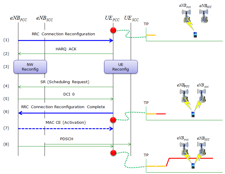
Three throughput snapshots on the right, taken at the three red marks on the UE lifeline. The rise does not arrive with the reconfiguration. It arrives two steps later.
Four lifelines, not two : eNB PCC and eNB SCC on the left, UE PCC and UE SCC on the right, and the UE SCC line stays idle until step (8).Blue is RRC, green is everything else : steps (1) and (6) are solid blue, step (7) is a dashed blue MAC CE, and the HARQ ACK, SR, DCI 0 and PDSCH arrows are green.Both reconfiguration steps run on the PCC : the command and the completion both touch the eNB PCC lifeline only.The throughput moves at the last snapshot : the first two show one carrier, and only the snapshot after step (8) shows the second one carrying data.
Step (7) is the one the specification has since made optional. SCellToAddMod-r10 gained an extension group in Release 15 carrying sCellState-r15, an ENUMERATED of activated and dormant. A secondary cell added with that field set to activated is already on when the reconfiguration completes, so no Activation MAC CE has to follow.
The rest of the sequence is fixed by what the messages are. The reconfiguration is an RRC message, so it needs a PDSCH to carry it and a HARQ acknowledgement in return. The completion is an RRC message travelling the other way, so it needs an uplink grant. The scheduling request at step (4) is how the UE asks for one.
Closer view on Carrier Aggregation Establishment - 3CC
Following sequence diagram shows an example for establishing the 3CC (Component Carrier) Carrier Aggregation. In 3CC case, there can be two different ways to establish the CA. One is to add SCC1 and SCC2 one by one and the other one is to add SCC1 and SCC2 at the same time. This sequence shows the case where we add SCC1/SCC2 at the same time.
In this case, overal sequence is exactly same as the 2CC case that we saw above.
(1) is the command (RRC message) to tel the UE to configure the Radio Stack (PHY, MAC) to establish the aggregated communication (Carrier Aggregration). You need to look into every details of RRC Connection Configuration message to fully understand this step.
(2) is the HARQ ACK from UE saying 'I got a PDSCH (carrying RRC Connection Reconfiguration).
(3) is the step where both UE and Network performs the necessary setup for Carrier Aggregation.
(4) is the step where UE send SR saying 'I need a physical resource to send some data (PUSCH carrying RRC Connection Reconfiguration Complete message in this case)'.
(5) is the step where Network allocate resource in response to step (4).
(6) is the step where UE reporting to network 'I am done with the setup and the setup is successful'. At this step, the setup has been established only at RRC layer and MAC layer for the second carrier is not yet activated.
(7) is the step where Network send a commond to UE saying 'Now activate MAC layer for the second carrier as well'.
(8) indicate the status where MAC/PHY for both carrier are fully activated.
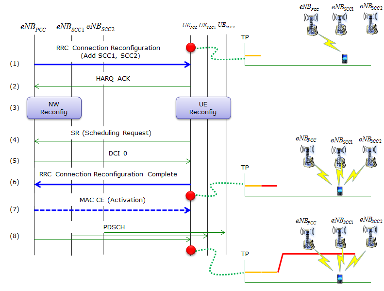
The same eight steps with one more carrier. Only the first arrow changes its label, and it changes by naming a second secondary cell rather than by adding a step.
One message adds both : step (1) is labelled RRC Connection Reconfiguration with Add SCC1 and SCC2, not two reconfigurations.The step count does not grow : the sequence still runs (1) to (8), which is what the paragraph above means by the same sequence.Six lifelines now : three on the network side and three on the UE side, with both secondary UE lines idle until step (8).One MAC CE covers both : step (7) is still a single dashed arrow, because the Activation MAC CE carries one bit per secondary cell.
The field behind that first arrow is a list, which is why one message is enough. sCellToAddModList-r10 is a SEQUENCE OF SCellToAddMod-r10, and the capture further down this page prints its bound as SIZE(1..maxSCell-r10[4]). Up to four secondary cells therefore fit in one reconfiguration.
That bound is also why the drawing stops at three carriers rather than at some larger number. Release 10 allowed four secondary cells and Release 13 raised the ceiling to thirty-one, but the shape of the message did not change. It is still one list in one reconfiguration.
RRC Message Examples
Following is an example that I get as of Jul 2013. This is only an example based on availble ASN implementation, it may not accurately reflect real implementation. This is only for your reference and to give you some idea on what kind of details you need to study to understand/implement Carrier Aggregation on your job. Don't try to blindly copy these elements as it is. I would not work.
NOTE : If you want to see the contents of full log with Amarisoft Log viewer, go to LogAnalysis section and click on 'Sample Log' in this tutorial of Amarisoft TechAcademy.
UE Capability Information
The most important thing you have to pay attention in UE Capability Information is CA Band combination as specified in RRC message as shown below. Two things have to agree before a combination is usable: the UE has to list it, and 36.101 has to define it. The captures below show the first, and the table screenshots further down show the second.
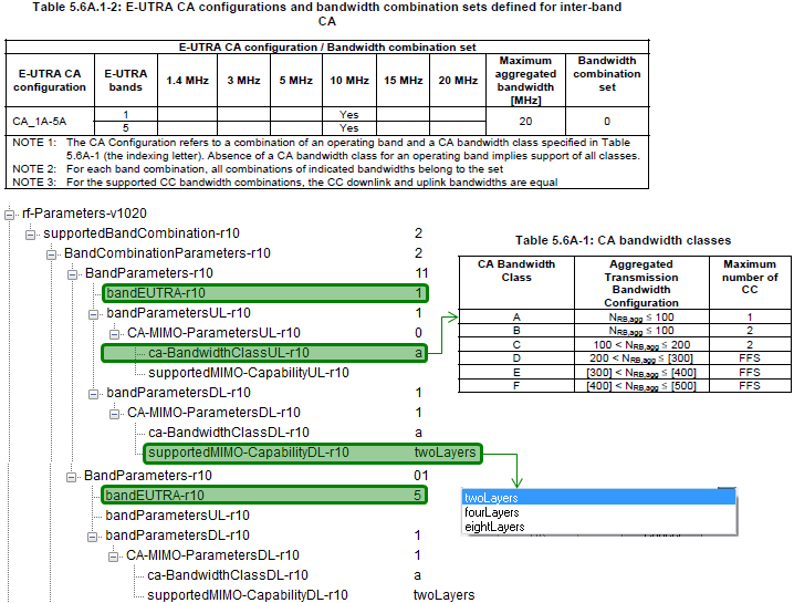
Following is the example for 2CC Carrier Aggregation supportability : DL 4A_17A, UL 4A
UE Capability Information, the rf-Parameters-v1020 branch for DL 4A_17A and UL 4A, decoded as a tree,
nonCriticalExtension
    rf-Parameters-v1020
        supportedBandCombination-r10: 1 item
            Item 0
                BandCombinationParameters-r10: 2 items
                    Item 0
                        BandParameters-r10
                            bandEUTRA-r10: 4
                            bandParametersUL-r10: 1 item
                                Item 0
                                    CA-MIMO-ParametersUL-r10
                                        ca-BandwidthClassUL-r10: a
                            bandParametersDL-r10: 1 item
                                Item 0
                                    CA-MIMO-ParametersDL-r10
                                        ca-BandwidthClassDL-r10: a
                                        supportedMIMO-CapabilityDL-r10: twoLayers
                    Item 1
                        BandParameters-r10
                            bandEUTRA-r10: 17
                            bandParametersDL-r10: 1 item
                                Item 0
                                    CA-MIMO-ParametersDL-r10
                                        ca-BandwidthClassDL-r10: a
                                        supportedMIMO-CapabilityDL-r10: twoLayers
Another important part is featureGroupIndicator (FGI) for r10. It has following items.
UE Capability Information, the featureGroupIndRel10-r10 bit string with every bit named,
     featureGroupIndRel10-r10: 00000000 [bit length 32, 0000 0000  0000 0000  0000 0000  0000 0000 decimal value 0]
         0... .... = Indicator 101: DMRS with OCC (orthogonal cover code) and SGH (sequence group hopping) disabling - Not supported
         .0.. .... = Indicator 102: Trigger type 1 SRS (aperiodic SRS) transmission (Up to X ports) - Not supported
         ..0. .... = Indicator 103: PDSCH TM9 when up to 4 CSI reference signal ports are configured - Not supported
         ...0 .... = Indicator 104: PDSCH TM9 for TDD when 8 CSI reference signal ports are configured - Not supported
         .... 0... = Indicator 105: PUCCH RM2-0 when PDSCH TM9 is configured and RM2-1 when PDSCH TM9
                                    and up to 4 CSI reference signal ports are configured - Not supported
         .... .0.. = Indicator 106: PUCCH RM2-1 when PDSCH TM9 and 8 CSI reference signal ports are configured - Not supported
         .... ..0. = Indicator 107: PUSCH RM2-0 when PDSCH TM9 is configured and RM2-2 when PDSCH TM9 and
                                    up to 4 CSI reference signal ports are configured - Not supported
         .... ...0 = Indicator 108: PUSCH RM2-2 when PDSCH TM9 and 8 CSI reference signal ports are configured - Not supported
         0... .... = Indicator 109: PUCCH RM1-1 submode 1 - Not supported
         .0.. .... = Indicator 110: PUCCH RM1-1 submode 2 - Not supported
         ..0. .... = Indicator 111: Measurement reporting trigger Event A6 - Not supported
         ...0 .... = Indicator 112: SCell addition within the Handover to EUTRA procedure - Not supported
         .... 0... = Indicator 113: Trigger type 0 SRS (periodic SRS) transmission on X Serving Cells - Not supported
         .... .0.. = Indicator 114: Reporting of both UTRA CPICH RSCP and Ec/N0 in a Measurement Report - Not supported
         .... ..0. = Indicator 115: Time domain ICIC RLM/RRM / ICIC RRM / ICIC CSI measurement sf restriction
                                    for the serving cell / neighbour cells - Not supported
         .... ...0 = Indicator 116: Relative transmit phase continuity for spatial multiplexing in UL - Not supported
CA Bandwidth Class
Following table shows Carrier Aggregation Bandwidth Class in terms of total number of RBs used by aggregated carrier. The class bounds the total rather than naming the carriers. Two very different aggregates can therefore share one class, and one modest looking pair can exceed it.
For example, CA Bandwidth Class 'B' says N_RB,agg <= 100. It means that total aggregated RB should be less than 100. Following shows some example cases which is allowed and not allowed configuration.
Case 1 : PCC = 10 Mhz (max 50 RB), SCC = 10 Mhz (max 50 RB).
It would give max aggregated RB is 50 RB +50 RB which is <= 100. So this is allowed.
Case 2 : PCC = 10 Mhz (max 50 RB), SCC = 15 Mhz (max 75 RB).
It would give max aggregated RB is 50 RB +75 RB which is >= 100. So this is not allowed.
36.101(Rel 13) - Table 5.6A-1: CA bandwidth classes and corresponding nominal guard bands
This bandwidth class supported by a UE is reported to network via UE Capability Information message as shown below.
Following is the example for 2CC Carrier Aggregation supportability : DL 4A_17A, UL 4A
The same rf-Parameters-v1020 branch again,
nonCriticalExtension
    rf-Parameters-v1020
        supportedBandCombination-r10: 1 item
            Item 0
                BandCombinationParameters-r10: 2 items
                    Item 0
                        BandParameters-r10
                            bandEUTRA-r10: 4
                            bandParametersUL-r10: 1 item
                                Item 0
                                    CA-MIMO-ParametersUL-r10
                                        ca-BandwidthClassUL-r10: a
                            bandParametersDL-r10: 1 item
                                Item 0
                                    CA-MIMO-ParametersDL-r10
                                        ca-BandwidthClassDL-r10: a
                                        supportedMIMO-CapabilityDL-r10: twoLayers
                    Item 1
                        BandParameters-r10
                            bandEUTRA-r10: 17
                            bandParametersDL-r10: 1 item
                                Item 0
                                    CA-MIMO-ParametersDL-r10
                                        ca-BandwidthClassDL-r10: a
                                        supportedMIMO-CapabilityDL-r10: twoLayers
Following is the example for Band class of a 3CC Carrier Aggregation : DL 1A_5A_7A, UL 1A
UE Capability Information for a three band combination, DL 1A_5A_7A and UL 1A, decoded as a tree,
nonCriticalExtension
    ue-Category-v1020: 6
    rf-Parameters-v1020
        supportedBandCombination-r10: 15 items
            Item 0
                BandCombinationParameters-r10: 3 items
                    Item 0
                        BandParameters-r10
                            bandEUTRA-r10: 1
                            bandParametersUL-r10: 1 item
                                Item 0
                                    CA-MIMO-ParametersUL-r10
                                        ca-BandwidthClassUL-r10: a (0)
                            bandParametersDL-r10: 1 item
                                Item 0
                                    CA-MIMO-ParametersDL-r10
                                        ca-BandwidthClassDL-r10: a (0)
                                        supportedMIMO-CapabilityDL-r10: twoLayers (0)
                    Item 1
                        BandParameters-r10
                            bandEUTRA-r10: 5
                            bandParametersDL-r10: 1 item
                                Item 0
                                    CA-MIMO-ParametersDL-r10
                                        ca-BandwidthClassDL-r10: a (0)
                                        supportedMIMO-CapabilityDL-r10: twoLayers (0)
                    Item 2
                        BandParameters-r10
                            bandEUTRA-r10: 7
                            bandParametersDL-r10: 1 item
                                Item 0
                                    CA-MIMO-ParametersDL-r10
                                        ca-BandwidthClassDL-r10: a (0)
                                        supportedMIMO-CapabilityDL-r10: twoLayers (0)
Followings are some more examples without the detailed RRC message.
- CA_46C-48E : This is 6CC CA because the class 'C' supports 2CC contiguous band and the class 'D' support 4CC configuous band.
- CA_2A-46A-48E : This is 6CC CA because there are two class 'A' band which support 1 CC for each band and one class 'E' that support 4 CC contiguous band.
- CA_2A-46C-48E : This is 7CC CA because there is one class 'A' which support 1CC, one class 'C' which support 2CC contiguous and one class 'E' that support 4CC contiguous bands.
Which Band Combination is allowed ?
Now the question you may ask is how can I know which band combination of bands a UE support in terms of Carrier Aggregation ? The answer is one field, and the trouble is its size. The list it belongs to may hold hundreds of entries, which is why Release 13 had to add a way of asking for less of it.
It is also supposed to be reported to network by the UE via UE Capability Information message. Followings are some of the possible IEs a UE may use depending on its release status.
Following is based on
RF-Parameters-v1020 ::= SEQUENCE {
    supportedBandCombination-r10 SupportedBandCombination-r10
}

RF-Parameters-v1090 ::= SEQUENCE {
    supportedBandCombination-v1090 SupportedBandCombination-v1090 OPTIONAL
}

RF-Parameters-v1130 ::= SEQUENCE {
    supportedBandCombination-v1130 SupportedBandCombination-v1130 OPTIONAL
}
All three are unchanged in 36.331 v19.3.0, down to the OPTIONAL on the later two. The number of them has changed instead. The RF-Parameters family now runs to thirty-two members, from RF-Parameters itself through RF-Parameters-v1800, and the three above are the first three that carry a band combination list.
The list lengths tell the same story as the count. SupportedBandCombination-r10 is SIZE (1..maxBandComb-r10) and 36.331 defines maxBandComb-r10 as 128. Release 11 added SupportedBandCombinationAdd-r11 with maxBandComb-r11 at 256, and Release 13 added SupportedBandCombinationReduced-r13 with maxBandComb-r13 at 384. Each entry is itself a list of up to maxSimultaneousBands-r10 bands, which is 64.
The definition of these IE is described as below in 36.331. Generally it sounds OK.. but it is not very clear to me if I go into one step deeper. For example, this definition does not clearly explain on which item in the list can be a PCC (Primary Component Carrier) and which should be SCC (Secondary Component Carrier). As far as I know, there is no priority of these items in terms of determining PCC/SCC, meaning either one should be allowed to be PCC depending on situation. But you may see some UE that allows only specific PCC/SCC mapping.
bandCombinationListEUTRA : One entry corresponding to each supported band combination listed in the same order as in supportedBandCombination.
BandCombinationParameters-v1090 : If included, the UE shall include the same number of entries, and listed in the same order, as in BandCombinationParameters-r10.
BandCombinationParameters-v1130 :The field is applicable to each supported CA bandwidth class combination (i.e. CA configuration in TS 36.101 Section 5.6A.1 indicated in the corresponding band combination
One example of Carrier Combination information in UE Capability Information is as follows. This example shows the UE allows Carrier Aggregation between band 4 and band 17.
The same branch once more,
nonCriticalExtension
    rf-Parameters-v1020
        supportedBandCombination-r10: 1 item
            Item 0
                BandCombinationParameters-r10: 2 items
                    Item 0
                        BandParameters-r10
                            bandEUTRA-r10: 4
                            bandParametersUL-r10: 1 item
                                Item 0
                                    CA-MIMO-ParametersUL-r10
                                        ca-BandwidthClassUL-r10: a
                            bandParametersDL-r10: 1 item
                                Item 0
                                    CA-MIMO-ParametersDL-r10
                                        ca-BandwidthClassDL-r10: a
                                        supportedMIMO-CapabilityDL-r10: twoLayers
                    Item 1
                        BandParameters-r10
                            bandEUTRA-r10: 17
                            bandParametersDL-r10: 1 item
                                Item 0
                                    CA-MIMO-ParametersDL-r10
                                        ca-BandwidthClassDL-r10: a
                                        supportedMIMO-CapabilityDL-r10: twoLayers
Following Table from 36.101 V12.5.0 (2014-11) shows all the possible (allowed) band combination of inter-band CA case. This list is likely to get extended as time goes on. So try to refer to latest spec.
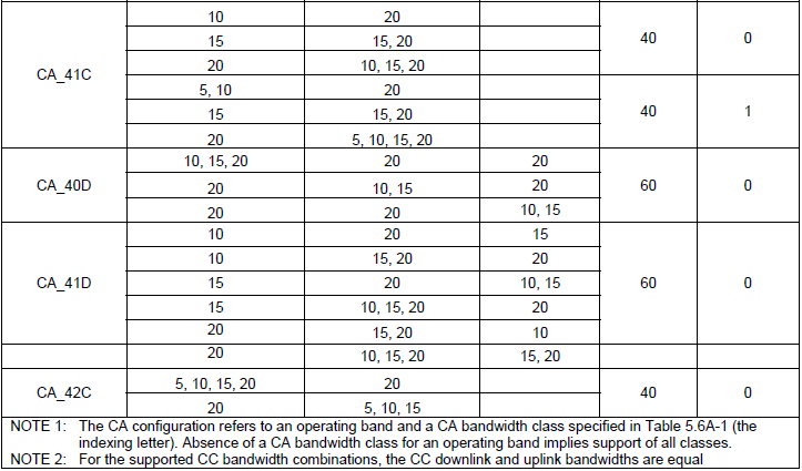
When you want to analyze UE capability, you can refer to bandEUTRA-r10 and ca-BandwidthClassDL-r10 in a BandCombinationParameters to figure out complete CA configuration as expressed in the first column of following tables.
36.101 Table 5.6A.1-1: E-UTRA CA configurations and bandwidth combination sets defined for intra-band contiguous CA
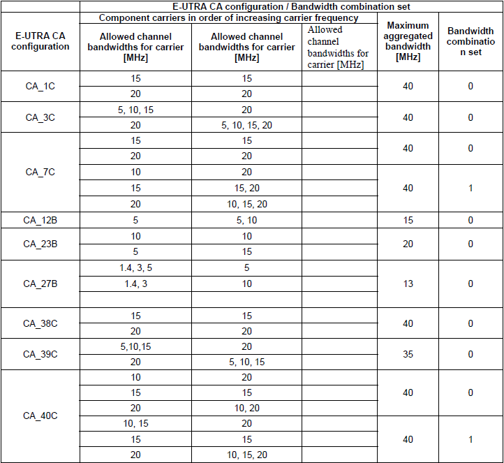
36.101 Table 5.6A.1-2: E-UTRA CA configurations and bandwidth combination sets defined for inter-band CA
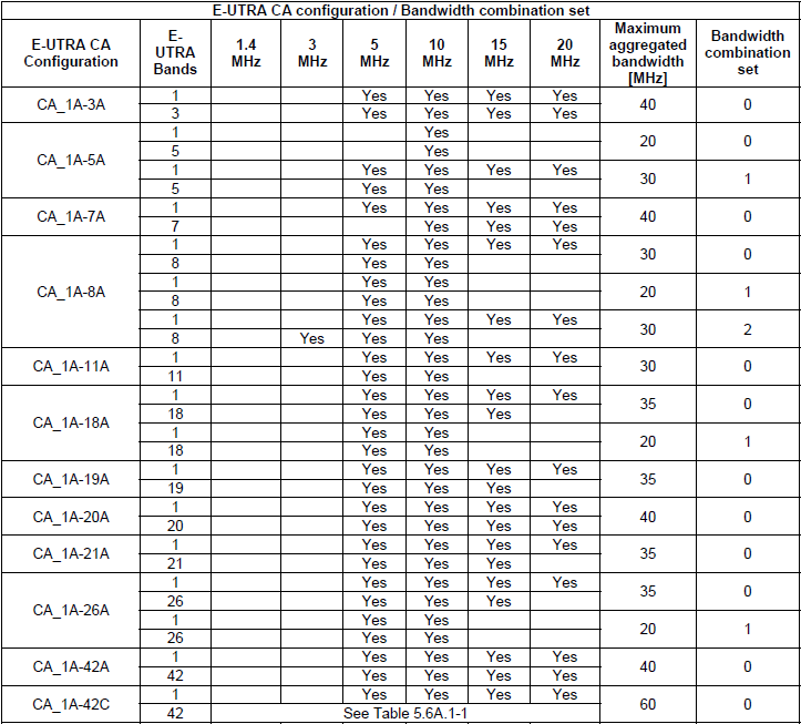
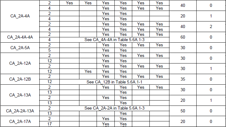
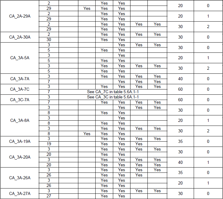
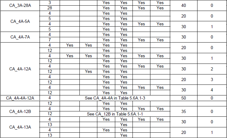
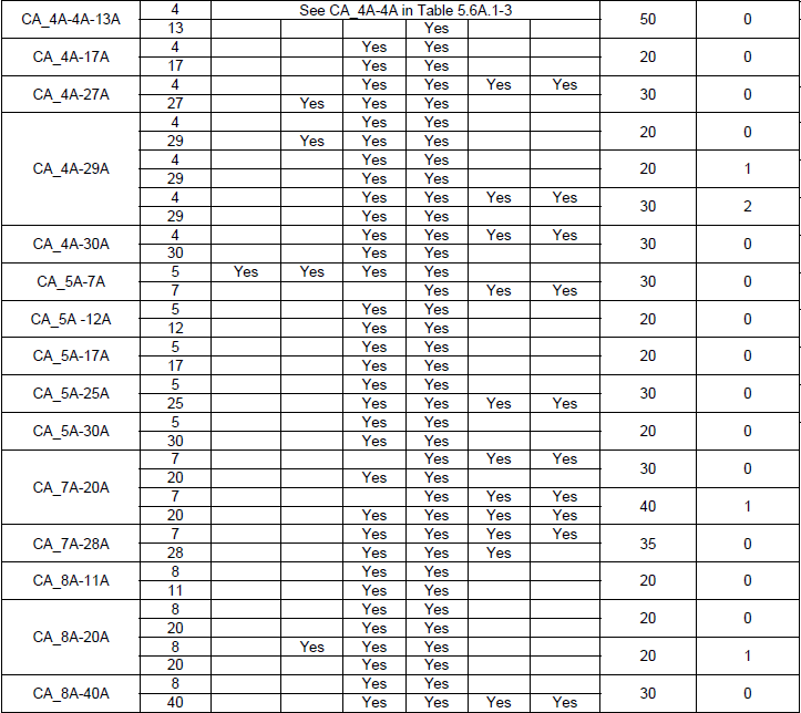
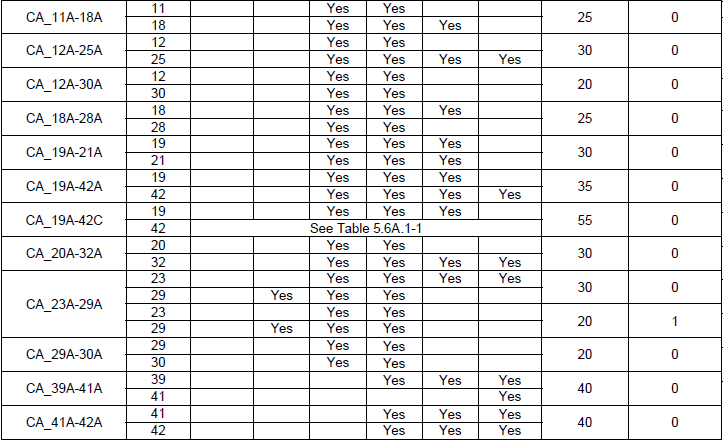
Table 5.6A.1-2a: E-UTRA CA configurations and bandwidth combination sets defined for inter-band CA (three bands)
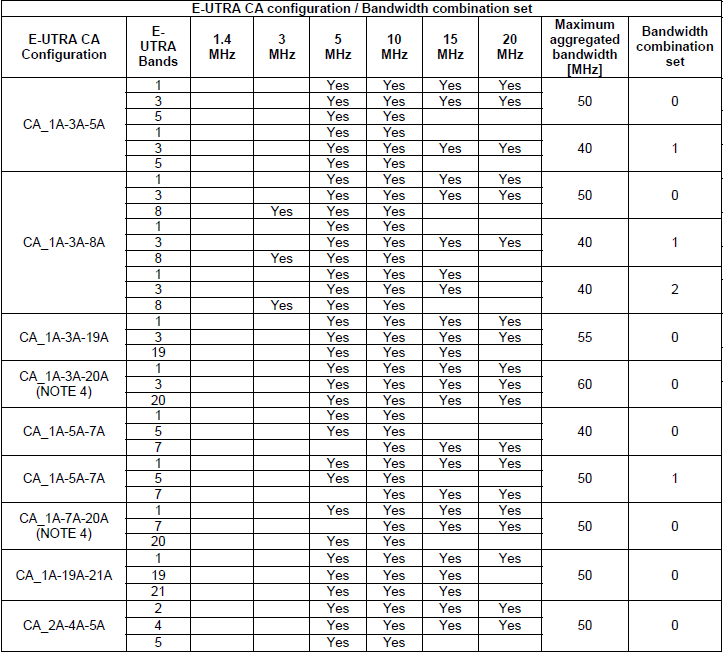

36.101 v13.2.1 Table 5.6A.1-2b: E-UTRA CA configurations and bandwidth combination sets defined for inter-band CA (four bands)
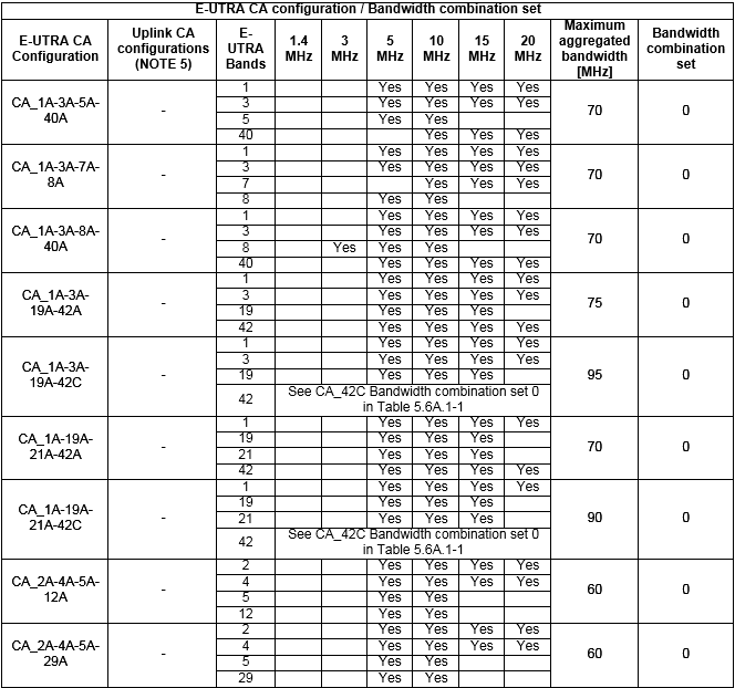
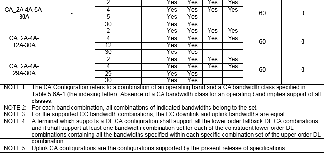
One of the UE capability information that may confuses you would be following IE. This IE shows you which band are supported by the UE in terms of single carrier. It is not about Carrier Aggregation.
UE Capability Information, the rf-Parameters branch listing the bands the UE supports on their own,
rf-Parameters
  supportedBandListEUTRA: 4 items
      Item 0
          SupportedBandEUTRA
              bandEUTRA: 2
              ..0. .... halfDuplex: False
      Item 1
          SupportedBandEUTRA
              bandEUTRA: 4
              .0.. .... halfDuplex: False
      Item 2
          SupportedBandEUTRA
              bandEUTRA: 5
              0... .... halfDuplex: False
      Item 3
          SupportedBandEUTRA
              bandEUTRA: 17
              .... ...0 halfDuplex: False
RRC Connection Reconfiguration for adding SCC - 2CC
Following is an example for RRC Connection Reconfiguration for LTE advanced (with focus on Carrier Aggregation). I just enabled all IE on ASN to give you full details of parameters, but it reality the implementation would start with very limited set of parameters enabled and leaving large portions of parameter to some 3GPP default or hardcoded configuration based on aggrement between UE maker and Network Operator.
First part you have to pay attention to this sample RRC message is sCellToAddModList-r10 which is for adding the SCC and next important thing is pucch-ConfigDedicated-v1020 which is for defining uplink control channel for reporting Ack/Nac for aggregated Carrier. With this pucch setup, UE is supposed to use PUCCH format 1b with channel selection. The operation of PUCCH 1b for 2CC Carrier Aggregation is very complicated and confusing. Refer to LTE Advanced PUCCH page for the details.
RRC Connection Reconfiguration adding a secondary cell, decoded as an ASN.1 tree by a tester,
+-rrcConnectionReconfiguration-r8 ::= SEQUENCE [000101]
  +-measConfig ::= SEQUENCE OPTIONAL:Omit
  +-mobilityControlInfo ::= SEQUENCE OPTIONAL:Omit
  +-dedicatedInfoNASList ::= SEQUENCE OF OPTIONAL:Omit
  +-radioResourceConfigDedicated ::= SEQUENCE [000101] OPTIONAL:Exist
  | +-srb-ToAddModList ::= SEQUENCE OF OPTIONAL:Omit
  | +-drb-ToAddModList ::= SEQUENCE OF OPTIONAL:Omit
  | +-drb-ToReleaseList ::= SEQUENCE OF OPTIONAL:Omit
  | +-mac-MainConfig ::= CHOICE [explicitValue] OPTIONAL:Exist
  | | +-explicitValue ::= SEQUENCE [000]
  | |   +-ul-SCH-Config ::= SEQUENCE OPTIONAL:Omit
  | |   +-drx-Config ::= CHOICE OPTIONAL:Omit
  | |   +-timeAlignmentTimerDedicated ::= ENUMERATED [infinity]
  | |   +-phr-Config ::= CHOICE OPTIONAL:Omit
  | |   +-EXTENSION ::= SEQUENCE [01]
  | |     +-VERSION-BRACKETS1 ::= SEQUENCE OPTIONAL:Omit
  | |     +-VERSION-BRACKETS2 ::= SEQUENCE [1] OPTIONAL:Exist
  | |       +-mac-MainConfig-v1020 ::= SEQUENCE [111] OPTIONAL:Exist
  | |         +-sCellDeactivationTimer-r10 ::= ENUMERATED [rf16] OPTIONAL:Exist
  | |         +-extendedBSR-Sizes-r10 ::= ENUMERATED [setup] OPTIONAL:Exist
  | |         +-extendedPHR-r10 ::= ENUMERATED [setup] OPTIONAL:Exist
  | +-sps-Config ::= SEQUENCE OPTIONAL:Omit
  | +-physicalConfigDedicated ::= SEQUENCE [0000000000] OPTIONAL:Exist
  | | +-pdsch-ConfigDedicated ::= SEQUENCE OPTIONAL:Omit
  | | +-pucch-ConfigDedicated ::= SEQUENCE OPTIONAL:Omit
  | | +-pusch-ConfigDedicated ::= SEQUENCE OPTIONAL:Omit
  | | +-uplinkPowerControlDedicated ::= SEQUENCE OPTIONAL:Omit
  | | +-tpc-PDCCH-ConfigPUCCH ::= CHOICE OPTIONAL:Omit
  | | +-tpc-PDCCH-ConfigPUSCH ::= CHOICE OPTIONAL:Omit
  | | +-cqi-ReportConfig ::= SEQUENCE OPTIONAL:Omit
  | | +-soundingRS-UL-ConfigDedicated ::= CHOICE OPTIONAL:Omit
  | | +-antennaInfo ::= CHOICE OPTIONAL:Omit
  | | +-schedulingRequestConfig ::= CHOICE OPTIONAL:Omit
  | | +-EXTENSION ::= SEQUENCE [010]
  | |   +-VERSION-BRACKETS1 ::= SEQUENCE OPTIONAL:Omit
  | |   +-VERSION-BRACKETS2 ::= SEQUENCE [00000111111] OPTIONAL:Exist
  | |   | +-antennaInfo-r10 ::= CHOICE OPTIONAL:Omit
  | |   | +-antennaInfoUL-r10 ::= SEQUENCE OPTIONAL:Omit
  | |   | +-cif-Presence-r10 ::= BOOLEAN OPTIONAL:Omit
  | |   | +-cqi-ReportConfig-r10 ::= SEQUENCE OPTIONAL:Omit
  | |   | +-csi-RS-Config-r10 ::= SEQUENCE OPTIONAL:Omit
  | |   | +-pucch-ConfigDedicated-v1020 ::= SEQUENCE [1111] OPTIONAL:Exist
  | |   | | +-pucch-Format-r10 ::= CHOICE [channelSelection-r10] OPTIONAL:Exist
  | |   | | | +-channelSelection-r10 ::= SEQUENCE [1]
  | |   | | |   +-n1PUCCH-AN-CS-r10 ::= CHOICE [setup] OPTIONAL:Exist
  | |   | | |     +-setup ::= SEQUENCE
  | |   | | |       +-n1PUCCH-AN-CS-List-r10 ::= SEQUENCE OF SIZE(1..2) [2]
  | |   | | |         +-N1PUCCH-AN-CS-r10 ::= SEQUENCE OF SIZE(1..4) [4]
  | |   | | |         | +- ::= INTEGER (0..2047) [10]
  | |   | | |         | +- ::= INTEGER (0..2047) [11]
  | |   | | |         | +- ::= INTEGER (0..2047) [12]
  | |   | | |         | +- ::= INTEGER (0..2047) [13]
  | |   | | |         +-N1PUCCH-AN-CS-r10 ::= SEQUENCE OF SIZE(1..4) [4]
  | |   | | |           +- ::= INTEGER (0..2047) [10]
  | |   | | |           +- ::= INTEGER (0..2047) [11]
  | |   | | |           +- ::= INTEGER (0..2047) [12]
  | |   | | |           +- ::= INTEGER (0..2047) [13]
  | |   | | +-twoAntennaPortActivatedPUCCH-Format1a1b-r10 ::= ENUMERATED [true] OPTIONAL:Exist
  | |   | | +-simultaneousPUCCH-PUSCH-r10 ::= ENUMERATED [true] OPTIONAL:Exist
  | |   | | +-n1PUCCH-AN-RepP1-r10 ::= INTEGER (0..2047) [0] OPTIONAL:Exist
  | |   | +-pusch-ConfigDedicated-v1020 ::= SEQUENCE [000] OPTIONAL:Exist
  | |   | | +-betaOffsetMC-r10 ::= SEQUENCE OPTIONAL:Omit
  | |   | | +-groupHoppingDisabled-r10 ::= ENUMERATED OPTIONAL:Omit
  | |   | | +-dmrs-WithOCC-Activated-r10 ::= ENUMERATED OPTIONAL:Omit
  | |   | +-schedulingRequestConfig-v1020 ::= SEQUENCE [0] OPTIONAL:Exist
  | |   | | +-sr-PUCCH-ResourceIndexP1-r10 ::= INTEGER OPTIONAL:Omit
  | |   | +-soundingRS-UL-ConfigDedicated-v1020 ::= SEQUENCE OPTIONAL:Exist
  | |   | | +-srs-AntennaPort-r10 ::= ENUMERATED [an1]
  | |   | +-soundingRS-UL-ConfigDedicatedAperiodic-r10 ::= CHOICE [setup] OPTIONAL:Exist
  | |   | | +-setup ::= SEQUENCE [11]
  | |   | |   +-srs-ConfigIndexAp-r10 ::= INTEGER (0..31) [0]
  | |   | |   +-srs-ConfigApDCI-Format4-r10 ::= SEQUENCE OF SIZE(1..3) [1] OPTIONAL:Exist
  | |   | |   | +-SRS-ConfigAp-r10 ::= SEQUENCE
  | |   | |   |   +-srs-AntennaPortAp-r10 ::= ENUMERATED [an1]
  | |   | |   |   +-srs-BandwidthAp-r10 ::= ENUMERATED [bw0]
  | |   | |   |   +-freqDomainPositionAp-r10 ::= INTEGER (0..23) [0]
  | |   | |   |   +-transmissionCombAp-r10 ::= INTEGER (0..1) [0]
  | |   | |   |   +-cyclicShiftAp-r10 ::= ENUMERATED [cs0]
  | |   | |   +-srs-ActivateAp-r10 ::= CHOICE [release] OPTIONAL:Exist
  | |   | |     +-release ::= NULL
  | |   | +-uplinkPowerControlDedicated-v1020 ::= SEQUENCE [11] OPTIONAL:Exist
  | |   |   +-deltaTxD-OffsetListPUCCH-r10 ::= SEQUENCE OPTIONAL:Exist
  | |   |   | +-deltaTxD-OffsetPUCCH-Format1-r10 ::= ENUMERATED [dB0]
  | |   |   | +-deltaTxD-OffsetPUCCH-Format1a1b-r10 ::= ENUMERATED [dB0]
  | |   |   | +-deltaTxD-OffsetPUCCH-Format22a2b-r10 ::= ENUMERATED [dB0]
  | |   |   | +-deltaTxD-OffsetPUCCH-Format3-r10 ::= ENUMERATED [dB0]
  | |   |   | +-EXTENSION ::= SEQUENCE
  | |   |   +-pSRS-OffsetAp-r10 ::= INTEGER (0..15) [0] OPTIONAL:Exist
  | |   +-VERSION-BRACKETS3 ::= SEQUENCE OPTIONAL:Omit
  | +-EXTENSION ::= SEQUENCE [00]
  |   +-VERSION-BRACKETS1 ::= SEQUENCE OPTIONAL:Omit
  |   +-VERSION-BRACKETS2 ::= SEQUENCE OPTIONAL:Omit
  +-securityConfigHO ::= SEQUENCE OPTIONAL:Omit
  +-nonCriticalExtension ::= SEQUENCE [01] OPTIONAL:Exist
    +-lateNonCriticalExtension ::= OCTET STRING OPTIONAL:Omit
    +-nonCriticalExtension ::= SEQUENCE [001] OPTIONAL:Exist
      +-otherConfig-r9 ::= SEQUENCE OPTIONAL:Omit
      +-fullConfig-r9 ::= ENUMERATED OPTIONAL:Omit
      +-nonCriticalExtension ::= SEQUENCE [010] OPTIONAL:Exist
        +-sCellToReleaseList-r10 ::= SEQUENCE OF OPTIONAL:Omit
        +-sCellToAddModList-r10 ::= SEQUENCE OF SIZE(1..maxSCell-r10[4]) [1] OPTIONAL:Exist
        | +-SCellToAddMod-r10 ::= SEQUENCE [111]
        |   +-sCellIndex-r10 ::= INTEGER (1..7) [1]
        |   +-cellIdentification-r10 ::= SEQUENCE OPTIONAL:Exist
        |   | +-physCellId-r10 ::= INTEGER (0..503) [2]
        |   | +-dl-CarrierFreq-r10 ::= INTEGER (0..maxEARFCN[65535]) [5790]
        |   +-radioResourceConfigCommonSCell-r10 ::= SEQUENCE [0] OPTIONAL:Exist
        |   | +-nonUL-Configuration-r10 ::= SEQUENCE [00]
        |   | | +-dl-Bandwidth-r10 ::= ENUMERATED [n50]
        |   | | +-antennaInfoCommon-r10 ::= SEQUENCE
        |   | | | +-antennaPortsCount ::= ENUMERATED [an2]
        |   | | +-mbsfn-SubframeConfigList-r10 ::= SEQUENCE OF OPTIONAL:Omit
        |   | | +-phich-Config-r10 ::= SEQUENCE
        |   | | | +-phich-Duration ::= ENUMERATED [normal]
        |   | | | +-phich-Resource ::= ENUMERATED [oneSixth]
        |   | | +-pdsch-ConfigCommon-r10 ::= SEQUENCE
        |   | | | +-referenceSignalPower ::= INTEGER (-60..50) [21]
        |   | | | +-p-b ::= INTEGER (0..3) [1]
        |   | | +-tdd-Config-r10 ::= SEQUENCE OPTIONAL:Omit
        |   | +-ul-Configuration-r10 ::= SEQUENCE OPTIONAL:Omit
        |   | +-EXTENSION ::= SEQUENCE
        |   +-radioResourceConfigDedicatedSCell-r10 ::= SEQUENCE [1] OPTIONAL:Exist
        |   | +-physicalConfigDedicatedSCell-r10 ::= SEQUENCE [11] OPTIONAL:Exist
        |   | | +-nonUL-Configuration-r10 ::= SEQUENCE [1111] OPTIONAL:Exist
        |   | | | +-antennaInfo-r10 ::= SEQUENCE [1] OPTIONAL:Exist
        |   | | | | +-transmissionMode-r10 ::= ENUMERATED [tm3]
        |   | | | | +-codebookSubsetRestriction-r10 ::= BIT STRING SIZE(ALIGNED) [00] OPTIONAL:Exist
        |   | | | | +-ue-TransmitAntennaSelection ::= CHOICE [release]
        |   | | | |   +-release ::= NULL
        |   | | | +-crossCarrierSchedulingConfig-r10 ::= SEQUENCE OPTIONAL:Exist
        |   | | | | +-schedulingCellInfo-r10 ::= CHOICE [own-r10]
        |   | | | |   +-own-r10 ::= SEQUENCE
        |   | | | |     +-cif-Presence-r10 ::= BOOLEAN [FALSE]
        |   | | | +-csi-RS-Config-r10 ::= SEQUENCE [11] OPTIONAL:Exist
        |   | | | | +-csi-RS-r10 ::= CHOICE [setup] OPTIONAL:Exist
        |   | | | | | +-setup ::= SEQUENCE
        |   | | | | |   +-antennaPortsCount-r10 ::= ENUMERATED [an1]
        |   | | | | |   +-resourceConfig-r10 ::= INTEGER (0..31) [0]
        |   | | | | |   +-subframeConfig-r10 ::= INTEGER (0..154) [0]
        |   | | | | |   +-p-C-r10 ::= INTEGER (-8..15) [-8]
        |   | | | | +-zeroTxPowerCSI-RS-r10 ::= CHOICE [setup] OPTIONAL:Exist
        |   | | | |   +-setup ::= SEQUENCE
        |   | | | |     +-zeroTxPowerResourceConfigList-r10 ::= BIT STRING SIZE(16) [0000000000000000]
        |   | | | |     +-zeroTxPowerSubframeConfig-r10 ::= INTEGER (0..154) [0]
        |   | | | +-pdsch-ConfigDedicated-r10 ::= SEQUENCE OPTIONAL:Exist
        |   | | |   +-p-a ::= ENUMERATED [dB-3]
        |   | | +-ul-Configuration-r10 ::= SEQUENCE [1111111] OPTIONAL:Exist
        |   | | | +-antennaInfoUL-r10 ::= SEQUENCE [11] OPTIONAL:Exist
        |   | | | | +-transmissionModeUL-r10 ::= ENUMERATED [tm1] OPTIONAL:Exist
        |   | | | | +-fourAntennaPortActivated-r10 ::= ENUMERATED [setup] OPTIONAL:Exist
        |   | | | +-pusch-ConfigDedicatedSCell-r10 ::= SEQUENCE [11] OPTIONAL:Exist
        |   | | | | +-groupHoppingDisabled-r10 ::= ENUMERATED [true] OPTIONAL:Exist
        |   | | | | +-dmrs-WithOCC-Activated-r10 ::= ENUMERATED [true] OPTIONAL:Exist
        |   | | | +-uplinkPowerControlDedicatedSCell-r10 ::= SEQUENCE [11] OPTIONAL:Exist
        |   | | | | +-p0-UE-PUSCH-r10 ::= INTEGER (-8..7) [-8]
        |   | | | | +-deltaMCS-Enabled-r10 ::= ENUMERATED [en0]
        |   | | | | +-accumulationEnabled-r10 ::= BOOLEAN [FALSE]
        |   | | | | +-pSRS-Offset-r10 ::= INTEGER (0..15) [0]
        |   | | | | +-pSRS-OffsetAp-r10 ::= INTEGER (0..15) [0] OPTIONAL:Exist
        |   | | | | +-filterCoefficient-r10 ::= ENUMERATED [fc0] OPTIONAL:Exist
        |   | | | | +-pathlossReferenceLinking-r10 ::= ENUMERATED [pCell]
        |   | | | +-cqi-ReportConfigSCell-r10 ::= SEQUENCE [111] OPTIONAL:Exist
        |   | | | | +-cqi-ReportModeAperiodic-r10 ::= ENUMERATED [rm12] OPTIONAL:Exist
        |   | | | | +-nomPDSCH-RS-EPRE-Offset-r10 ::= INTEGER (-1..6) [-1]
        |   | | | | +-cqi-ReportPeriodicSCell-r10 ::= CHOICE [setup] OPTIONAL:Exist
        |   | | | | | +-setup ::= SEQUENCE [0000]
        |   | | | | |   +-cqi-PUCCH-ResourceIndex-r10 ::= INTEGER (0..1184) [0]
        |   | | | | |   +-cqi-PUCCH-ResourceIndexP1-r10 ::= INTEGER OPTIONAL:Omit
        |   | | | | |   +-cqi-pmi-ConfigIndex ::= INTEGER (0..1023) [0]
        |   | | | | |   +-cqi-FormatIndicatorPeriodic-r10 ::= CHOICE [widebandCQI-r10]
        |   | | | | |   | +-widebandCQI-r10 ::= SEQUENCE [0]
        |   | | | | |   |   +-csi-ReportMode-r10 ::= ENUMERATED OPTIONAL:Omit
        |   | | | | |   +-ri-ConfigIndex ::= INTEGER OPTIONAL:Omit
        |   | | | | |   +-simultaneousAckNackAndCQI ::= BOOLEAN [FALSE]
        |   | | | | |   +-cqi-Mask-r9 ::= ENUMERATED OPTIONAL:Omit
        |   | | | | |   +-csi-ConfigIndex-r10 ::= CHOICE OPTIONAL:Omit
        |   | | | | +-pmi-RI-Report-r10 ::= ENUMERATED [setup] OPTIONAL:Exist
        |   | | | +-soundingRS-UL-ConfigDedicated-r10 ::= CHOICE [setup] OPTIONAL:Exist
        |   | | | | +-setup ::= SEQUENCE
        |   | | | |   +-srs-Bandwidth ::= ENUMERATED [bw0]
        |   | | | |   +-srs-HoppingBandwidth ::= ENUMERATED [hbw0]
        |   | | | |   +-freqDomainPosition ::= INTEGER (0..23) [0]
        |   | | | |   +-duration ::= BOOLEAN [FALSE]
        |   | | | |   +-srs-ConfigIndex ::= INTEGER (0..1023) [0]
        |   | | | |   +-transmissionComb ::= INTEGER (0..1) [0]
        |   | | | |   +-cyclicShift ::= ENUMERATED [cs0]
        |   | | | +-soundingRS-UL-ConfigDedicated-v1020 ::= SEQUENCE OPTIONAL:Exist
        |   | | | | +-srs-AntennaPort-r10 ::= ENUMERATED [an1]
        |   | | | +-soundingRS-UL-ConfigDedicatedAperiodic-r10 ::= CHOICE [setup] OPTIONAL:Exist
        |   | | |   +-setup ::= SEQUENCE [11]
        |   | | |     +-srs-ConfigIndexAp-r10 ::= INTEGER (0..31) [0]
        |   | | |     +-srs-ConfigApDCI-Format4-r10 ::= SEQUENCE OF SIZE(1..3) [1] OPTIONAL:Exist
        |   | | |     | +-SRS-ConfigAp-r10 ::= SEQUENCE
        |   | | |     |   +-srs-AntennaPortAp-r10 ::= ENUMERATED [an1]
        |   | | |     |   +-srs-BandwidthAp-r10 ::= ENUMERATED [bw0]
        |   | | |     |   +-freqDomainPositionAp-r10 ::= INTEGER (0..23) [0]
        |   | | |     |   +-transmissionCombAp-r10 ::= INTEGER (0..1) [0]
        |   | | |     |   +-cyclicShiftAp-r10 ::= ENUMERATED [cs0]
        |   | | |     +-srs-ActivateAp-r10 ::= CHOICE [release] OPTIONAL:Exist
        |   | | |       +-release ::= NULL
        |   | | +-EXTENSION ::= SEQUENCE
        |   | +-EXTENSION ::= SEQUENCE
        |   +-EXTENSION ::= SEQUENCE
The tree prints the constraint names as well as the values, which is what makes it readable. sCellToAddModList-r10 is shown as SEQUENCE OF SIZE(1..maxSCell-r10[4]), and 36.331 v19.3.0 still defines maxSCell-r10 as 4. Four secondary cells is the Release 10 ceiling, and it is why this capture can only ever describe a five carrier aggregate at most.
Release 13 raised that ceiling without touching the Release 10 field. maxSCell-r13 is 31, and SCellIndex-r13 runs from 1 to 31 where SCellIndex-r10 runs from 1 to 7. A UE configured with more than four secondary cells is therefore carrying the r13 list, not the one in this capture.
The decoder prints the bound : SIZE(1..maxSCell-r10[4]) shows both the constant name and its value.Four secondary cells in Release 10 : maxSCell-r10 is 4, so this list tops out at a five carrier aggregate.Thirty-one in Release 13 : maxSCell-r13 is 31 and SCellIndex-r13 runs to 31.OPTIONAL:Exist and OPTIONAL:Omit are the decoder's words : they say whether an optional field was present in this message, not what the specification allows.
RRC Connection Reconfiguration for Measuring the Second Cell
To make it sure that Network triggers adding the second cell only when UE can detect the second cell with a certain signal condition, Network usually perform measurement for the second cell. One of the example of this measurement process is as follows.
According to 36.331,
ThresholdEUTRA
For RSRP: RSRP based threshold for event evaluation. The actual value is IE value . 140 dBm.
For RSRQ: RSRQ based threshold for event evaluation. The actual value is (IE value . 40)/2 dB.
EUTRAN configures the same threshold quantity for all the thresholds of an event.
RRC Connection Reconfiguration carrying the measurement configuration, decoded as an ASN.1 tree,
+-rrcConnectionReconfiguration ::= SEQUENCE
  +-rrc-TransactionIdentifier ::= INTEGER (0..3) [0]
  +-criticalExtensions ::= CHOICE [c1]
    +-c1 ::= CHOICE [rrcConnectionReconfiguration-r8]
      +-rrcConnectionReconfiguration-r8 ::= SEQUENCE [100000]
        +-measConfig ::= SEQUENCE [01010111000] OPTIONAL:Exist
        | +-measObjectToRemoveList ::= SEQUENCE OF OPTIONAL:Omit
        | +-measObjectToAddModList ::= SEQUENCE OF SIZE(1..maxObjectId[32]) [2] OPTIONAL:Exist
        | | +-MeasObjectToAddMod ::= SEQUENCE
        | | | +-measObjectId ::= INTEGER (1..maxObjectId[32]) [1]
        | | | +-measObject ::= CHOICE [measObjectEUTRA]
        | | |   +-measObjectEUTRA ::= SEQUENCE [100000]
        | | |     +-carrierFreq ::= INTEGER (0..maxEARFCN[65535]) [1575]
        | | |     +-allowedMeasBandwidth ::= ENUMERATED [mbw50]
        | | |     +-presenceAntennaPort1 ::= BOOLEAN [FALSE]
        | | |     +-neighCellConfig ::= BIT STRING SIZE(2) [01]
        | | |     +-offsetFreq ::= ENUMERATED [dB0] OPTIONAL:Exist
        | | |     +-cellsToRemoveList ::= SEQUENCE OF OPTIONAL:Omit
        | | |     +-cellsToAddModList ::= SEQUENCE OF OPTIONAL:Omit
        | | |     +-blackCellsToRemoveList ::= SEQUENCE OF OPTIONAL:Omit
        | | |     +-blackCellsToAddModList ::= SEQUENCE OF OPTIONAL:Omit
        | | |     +-cellForWhichToReportCGI ::= INTEGER OPTIONAL:Omit
        | | |     +-EXTENSION ::= SEQUENCE [0]
        | | |       +-VERSION-BRACKETS1 ::= SEQUENCE OPTIONAL:Omit
        | | +-MeasObjectToAddMod ::= SEQUENCE
        | |   +-measObjectId ::= INTEGER (1..maxObjectId[32]) [2]
        | |   +-measObject ::= CHOICE [measObjectEUTRA]
        | |     +-measObjectEUTRA ::= SEQUENCE [100000]
        | |       +-carrierFreq ::= INTEGER (0..maxEARFCN[65535]) [2525]
        | |       +-allowedMeasBandwidth ::= ENUMERATED [mbw50]
        | |       +-presenceAntennaPort1 ::= BOOLEAN [FALSE]
        | |       +-neighCellConfig ::= BIT STRING SIZE(2) [01]
        | |       +-offsetFreq ::= ENUMERATED [dB0] OPTIONAL:Exist
        | |       +-cellsToRemoveList ::= SEQUENCE OF OPTIONAL:Omit
        | |       +-cellsToAddModList ::= SEQUENCE OF OPTIONAL:Omit
        | |       +-blackCellsToRemoveList ::= SEQUENCE OF OPTIONAL:Omit
        | |       +-blackCellsToAddModList ::= SEQUENCE OF OPTIONAL:Omit
        | |       +-cellForWhichToReportCGI ::= INTEGER OPTIONAL:Omit
        | |       +-EXTENSION ::= SEQUENCE [0]
        | |         +-VERSION-BRACKETS1 ::= SEQUENCE OPTIONAL:Omit
        | +-reportConfigToRemoveList ::= SEQUENCE OF OPTIONAL:Omit
        | +-reportConfigToAddModList ::= SEQUENCE OF SIZE(1..maxReportConfigId[32]) [1]
        | | +-ReportConfigToAddMod ::= SEQUENCE
        | |   +-reportConfigId ::= INTEGER (1..maxReportConfigId[32]) [1]
        | |   +-reportConfig ::= CHOICE [reportConfigEUTRA]
        | |     +-reportConfigEUTRA ::= SEQUENCE
        | |       +-triggerType ::= CHOICE [event]
        | |       | +-event ::= SEQUENCE
        | |       |   +-eventId ::= CHOICE [eventA4]
        | |       |   | +-eventA4 ::= SEQUENCE
        | |       |   |   +-a4-Threshold ::= CHOICE [threshold-RSRP]
        | |       |   |     +-threshold-RSRP ::= INTEGER (0..97) [50]
        | |       |   +-hysteresis ::= INTEGER (0..30) [0]
        | |       |   +-timeToTrigger ::= ENUMERATED [ms256]
        | |       +-triggerQuantity ::= ENUMERATED [rsrp]
        | |       +-reportQuantity ::= ENUMERATED [both]
        | |       +-maxReportCells ::= INTEGER (1..maxCellReport[8]) [1]
        | |       +-reportInterval ::= ENUMERATED [ms1024]
        | |       +-reportAmount ::= ENUMERATED [r1]
        | |       +-EXTENSION ::= SEQUENCE [00]
        | |         +-VERSION-BRACKETS1 ::= SEQUENCE OPTIONAL:Omit
        | |         +-VERSION-BRACKETS2 ::= SEQUENCE OPTIONAL:Omit
        | +-measIdToRemoveList ::= SEQUENCE OF OPTIONAL:Omit
        | +-measIdToAddModList ::= SEQUENCE OF SIZE(1..maxMeasId[32]) [2] OPTIONAL:Exist
        | | +-MeasIdToAddMod ::= SEQUENCE
        | | | +-measId ::= INTEGER (1..maxMeasId[32]) [1]
        | | | +-measObjectId ::= INTEGER (1..maxObjectId[32]) [1]
        | | | +-reportConfigId ::= INTEGER (1..maxReportConfigId[32]) [1]
        | | +-MeasIdToAddMod ::= SEQUENCE
        | |   +-measId ::= INTEGER (1..maxMeasId[32]) [2]
        | |   +-measObjectId ::= INTEGER (1..maxObjectId[32]) [2]
        | |   +-reportConfigId ::= INTEGER (1..maxReportConfigId[32]) [1]
        | +-quantityConfig ::= SEQUENCE [1000] OPTIONAL:Exist
        | | +-quantityConfigEUTRA ::= SEQUENCE [00] OPTIONAL:Exist
        | | | +-filterCoefficientRSRP ::= ENUMERATED OPTIONAL:Omit
        | | | +-filterCoefficientRSRQ ::= ENUMERATED OPTIONAL:Omit
        | | +-quantityConfigUTRA ::= SEQUENCE OPTIONAL:Omit
        | | +-quantityConfigGERAN ::= SEQUENCE OPTIONAL:Omit
        | | +-quantityConfigCDMA2000 ::= SEQUENCE OPTIONAL:Omit
        | | +-EXTENSION ::= SEQUENCE [0]
        | |   +-VERSION-BRACKETS1 ::= SEQUENCE OPTIONAL:Omit
        | +-measGapConfig ::= CHOICE [setup] OPTIONAL:Exist
        | | +-setup ::= SEQUENCE
        | |   +-gapOffset ::= CHOICE [gp0]
        | |     +-gp0 ::= INTEGER (0..39) [30]
        | +-s-Measure ::= INTEGER OPTIONAL:Omit
        | +-preRegistrationInfoHRPD ::= SEQUENCE OPTIONAL:Omit
        | +-speedStatePars ::= CHOICE OPTIONAL:Omit
        | +-EXTENSION ::= SEQUENCE [0]
        |   +-VERSION-BRACKETS1 ::= SEQUENCE OPTIONAL:Omit
        +-mobilityControlInfo ::= SEQUENCE OPTIONAL:Omit
        +-dedicatedInfoNASList ::= SEQUENCE OF OPTIONAL:Omit
        +-radioResourceConfigDedicated ::= SEQUENCE OPTIONAL:Omit
        +-securityConfigHO ::= SEQUENCE OPTIONAL:Omit
        +-nonCriticalExtension ::= SEQUENCE OPTIONAL:Omit
The Measurement Report the UE sends back, decoded as an ASN.1 tree,
+-measurementReport ::= SEQUENCE
  +-criticalExtensions ::= CHOICE [c1]
    +-c1 ::= CHOICE [measurementReport-r8]
      +-measurementReport-r8 ::= SEQUENCE [0]
        +-measResults ::= SEQUENCE [1]
        | +-measId ::= INTEGER (1..maxMeasId[32]) [2]
        | +-measResultPCell ::= SEQUENCE
        | | +-rsrpResult ::= INTEGER (0..97) [73]
        | | +-rsrqResult ::= INTEGER (0..34) [20]
        | +-measResultNeighCells ::= CHOICE [measResultListEUTRA] OPTIONAL:Exist
        | | +-measResultListEUTRA ::= SEQUENCE OF SIZE(1..maxCellReport[8]) [1]
        | |   +-MeasResultEUTRA ::= SEQUENCE [0]
        | |     +-physCellId ::= INTEGER (0..503) [0]
        | |     +-cgi-Info ::= SEQUENCE OPTIONAL:Omit
        | |     +-measResult ::= SEQUENCE [11]
        | |       +-rsrpResult ::= INTEGER (0..97) [73] OPTIONAL:Exist
        | |       +-rsrqResult ::= INTEGER (0..34) [29] OPTIONAL:Exist
        | |       +-EXTENSION ::= SEQUENCE [0]
        | |         +-VERSION-BRACKETS1 ::= SEQUENCE OPTIONAL:Omit
        | +-EXTENSION ::= SEQUENCE [00]
        |   +-VERSION-BRACKETS1 ::= SEQUENCE OPTIONAL:Omit
        |   +-VERSION-BRACKETS2 ::= SEQUENCE OPTIONAL:Omit
        +-nonCriticalExtension ::= SEQUENCE OPTIONAL:Omit
The band combination list after Release 11
Three structures answered the band combination question in Release 10 and 11, and the page above quotes all three. The answer did not stay that small. By Release 13 the list had grown far enough that the network had to be given a way to ask for less of it.
The first sign is in the names. RF-Parameters-v1180 added three fields at once: freqBandRetrieval-r11, requestedBands-r11 and supportedBandCombinationAdd-r11. The last of those is a second combination list beside the first, holding up to 256 entries where the original holds 128.
Following is based on
RF-Parameters-v1180 ::=             SEQUENCE {
    freqBandRetrieval-r11                   ENUMERATED {supported}          OPTIONAL,
    requestedBands-r11                      SEQUENCE (SIZE (1.. maxBands)) OF FreqBandIndicator-r11                     OPTIONAL,
    supportedBandCombinationAdd-r11         SupportedBandCombinationAdd-r11     OPTIONAL
}

RF-Parameters-v1310 ::=             SEQUENCE {
    eNB-RequestedParameters-r13         SEQUENCE {
        reducedIntNonContCombRequested-r13  ENUMERATED {true}                       OPTIONAL,
        requestedCCsDL-r13                  INTEGER (2..32)                         OPTIONAL,
        requestedCCsUL-r13                  INTEGER (2..32)                         OPTIONAL,
        skipFallbackCombRequested-r13       ENUMERATED {true}                       OPTIONAL
    }                                                                               OPTIONAL,
    maximumCCsRetrieval-r13                 ENUMERATED {supported}                  OPTIONAL,
    skipFallbackCombinations-r13            ENUMERATED {supported}                  OPTIONAL,
    reducedIntNonContComb-r13               ENUMERATED {supported}                  OPTIONAL,
    supportedBandListEUTRA-v1310            SupportedBandListEUTRA-v1310            OPTIONAL,
    supportedBandCombinationReduced-r13     SupportedBandCombinationReduced-r13     OPTIONAL
}
The inner SEQUENCE is the interesting half. eNB-RequestedParameters is what the network sends into the capability enquiry, and every field in it narrows the answer. requestedCCsDL and requestedCCsUL are INTEGER (2..32), and 36.331 describes them as the maximum number of component carriers the network is asking about. A network that only supports three carriers has no reason to receive combinations for thirty-two.
skipFallbackCombRequested does the same job from the other direction. 36.331 says it requests the UE to exclude fallback band combinations from capability signalling, and the reason those can be excluded is written on the last table screenshot above. NOTE 4 of 36.101 Table 5.6A.1-2b says a terminal supporting a downlink CA configuration shall support all the lower order fallback downlink CA combinations. They are implied, so they need not be listed.
reducedIntNonContCombRequested trims a third group, the intra-band non-contiguous combinations. The three outer ENUMERATED fields beside them, maximumCCsRetrieval, skipFallbackCombinations and reducedIntNonContComb, are the UE saying whether it understands each request at all.
The result of all three is supportedBandCombinationReduced-r13, and 36.331 describes it as the supported CA band combinations which may include the fallback combinations. Release 13 therefore has three combination lists in the same message: the original, the additional one from Release 11, and the reduced one.
The same pressure shows on the configuration side. maxSCell-r10 is 4 and SCellIndex-r10 runs from 1 to 7, while maxSCell-r13 is 31 and SCellIndex-r13 runs from 1 to 31. The capture further up this page prints the Release 10 bound as SIZE(1..maxSCell-r10[4]), which is the decoder showing the constant it resolved.
Thirty-two RF-Parameters members : the chain runs from RF-Parameters to RF-Parameters-v1800, and only the first few carry the lists this page quotes.128, then 256, then 384 : maxBandComb-r10, maxBandComb-r11 and maxBandComb-r13 are the sizes of the three combination lists.The network asks for a bounded answer : requestedCCsDL and requestedCCsUL are INTEGER (2..32), the maximum number of carriers the network wants combinations for.Fallback combinations are implied, not listed : 36.101 makes support of the lower order combinations mandatory, so 36.331 lets the network ask for them to be left out.The UE says what it understands : maximumCCsRetrieval, skipFallbackCombinations and reducedIntNonContComb each report whether the matching request is supported.Secondary cells went from 4 to 31 : maxSCell-r10 is 4 and maxSCell-r13 is 31, with SCellIndex widening to match.
Reference
Two specifications carry everything quoted on this page. 36.331 defines the messages and the fields. 36.101 defines which band combinations exist for those fields to name. The third entry is the test walkthrough the contents block already points at.
- [1] 36.331 : 3GPP - E-UTRA; Radio Resource Control, v19.3.0. The RF-Parameters family, SCellToAddMod-r10 and the maxBandComb and maxSCell constants are quoted above.
- [2] 36.101 : 3GPP - E-UTRA; UE radio transmission and reception. Table 5.6A-1 holds the CA bandwidth classes and Tables 5.6A.1-1 to 5.6A.1-2b hold the band combinations shown above.
- [3] Amarisoft TechAcademy : the carrier aggregation test procedure and log that the contents block links to.