|
HARQ in Detail
What is H-ARQ ? Why it uses the term "Hybrid" ?
First think about the term ARQ. ARQ stands for Automatic Repeat Request and you would have heard this a lot if you had experience of studying IP communication (I think you can google a lot of tutorials on this, so I would not explain about what is ARQ here). The "H" in HARQ means "Hybrid" which implies that HARQ is a combination of "Something" and "ARQ".
Then what would be the "Something" ? The "Something" is FEC (forward error correction). FEC is also not LTE specific technology and a kind of generic error correction mechanism. So I would like you to google something about FEC.
- Characteristics of 5G HARQ
- ACK/NACK Timing in Slot Configuration
- What is Redudandancy Version ? and How it works ?
- How many HARQ processor ?
- Example
How HARQ Works ?
The transmission and reception process involves transmitting data, receiving ACK or NACK, and performing retransmissions if necessary. The whole procedure (transmission, reception and ack/nack reporting, retransmission) is done by a speciall process called HARQ process. A few typical examples of HARQ operation are illustrated below.
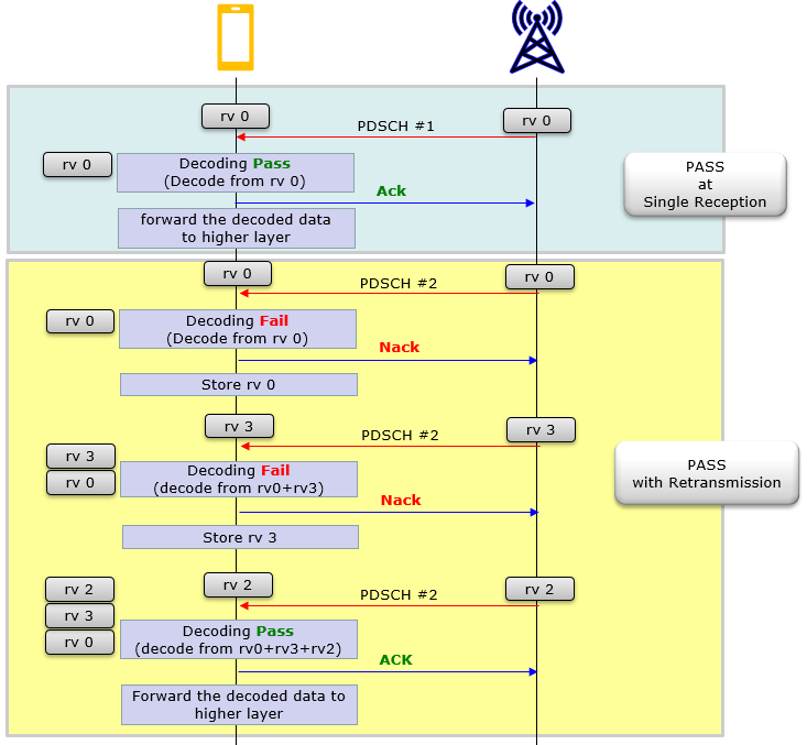
Followings are descriptions for the diagam shown above.
- Transmission: The gNB (base station) transmits PDSCH with rv 0 to the UE (User Equipment) over the PDSCH.
- Reception: The UE receives the data and performs error detection using the CRC (Cyclic Redundancy Check).
- ACK/NACK: If the CRC is OK, the UE sends an ACK message to the eNodeB through PUCCH or PUSCH, indicating successful reception.
- Since the transmission was successful, there is no need for retransmissions in this case. There is no need to save the data in HARQ buffer and UE forward the decoded data to higher layer.
- First Transmission: The gNB (base station) transmits PDSCH with rv 0 to the UE (User Equipment) over the PDSCH.
- First Reception: The UE receives the data and performs error detection using the CRC. The CRC fails, indicating a decoding failure.
- First ACK/NACK: The UE sends a NACK message to the gNB through the PUCCH or PUSCH, indicating a decoding failure.
- First Retransmission: Based on the NACK, the gNB retransmits the data with a different RV (e.g., RV=3) to increase the likelihood of successful decoding.
- Second Reception: The UE receives the retransmitted data and performs error detection using the CRC. The CRC fails again, indicating another decoding failure. When UE decode data, it combines the previous data stored in the buffer and the current data it just recieved, and then decode the combined data.
- Second ACK/NACK: The UE sends another NACK message to the eNodeB, indicating a second decoding failure.
- Second Retransmission: Based on the second NACK, the gNB retransmits the data again with a different RV (e.g., RV=2) to further increase the likelihood of successful decoding.
- Third Reception: The UE receives the retransmitted data and performs error detection using the CRC. The CRC is OK this time, indicating successful decoding. When UE decode data, it combines all the previous data stored in the buffer and the current data it just recieved, and then decode the combined data.
- Third ACK/NACK: The UE sends an ACK message to the gNB, indicating successful reception after the third transmission attempt.
NOTE : You see a new concept called rv (redundancy version). You will get to know of this in later section.
Characteristics of 5G HARQ
Basic concept of HARQ in NR is similar to LTE HARQ, but there is some mintor differences in terms of the details. In this page, I will try to explain NR HARQ in comparison to LTE HARQ. So if you are already familiar with LTE HARQ, it will be a great help to understand NR HARQ.
ACK/NACK Timing in Slot Configuration
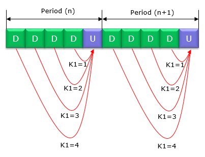
Even though both TDD and FDD are allowed in NR, it is likely that TDD will be used in most case of NR operation. So it would be beneficial if you have good understandings on how HARQ ACK/NACK timing is determined in TDD LTE (See here if you are not familiar with TDD LTE HARQ Timing). As you know, TDD LTE HARQ ACK/NACK timing is specified by a predefined table. But in TDD NR, HARQ ACK/NACK timing is fully configurable. You can configure HARQ ACK/NACK timing for a specific PDSCH by specifying the parameter K1.
As an example, let's supposed your slot configuration is DDDDU with 2.5 ms period. You can configure in such a way that HARQ ACK/NACK for all the PDSCH is transmitted at the same UL slot by specifying K1 as follows. (If you are not familiar with what is K1 and how these values can be configured and informed to UE, see here).
If necessary, you can configure HARQ ACK/NACK timing as flexible as shown below.
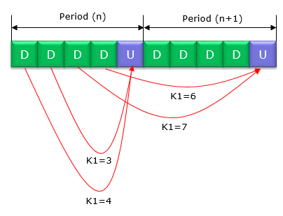
You may ask 'How far HARQ ACK/NACK can be away from the transmitted PDSCH ? It is up to the maximum K1 value settable in RRC message. As of 2018 Sep specification, the maximum K1 value is 15 as you see here )
What is Redudandancy Version ? and How it works ?
When a transmission (or retransmission) takes place, the original data bits are encoded using a specific Forward Error Correction (FEC) scheme(e.g, LDPC). The encoded bits are then punctured or rate-matched to create a set of output bits for transmission. The redundancy version determines which bits are selected for transmission, and different RVs will result in different sets of bits being sent.
The selection of bits in different redundancy versions is usually achieved using a circular buffer and a specific interleaving pattern for each RV. As a result, each RV will provide a different portion of the rate-matched output, increasing the chances of successful decoding at the receiver
Each of the rv (redundancy version) is constructed from the bits in a circular buffer that are stored during the rate match process. Each of the rv bits is illustrated as below.
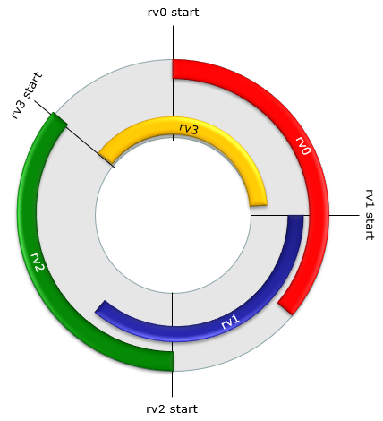
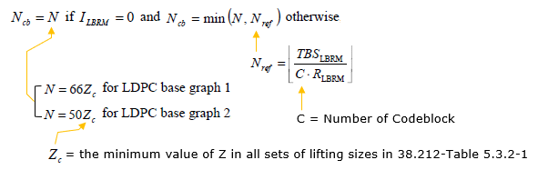
Start of each rv is specified by 3GPP as below :
< 38.212-Table 5.4.2.1-2: Starting position of different redundancy versions >
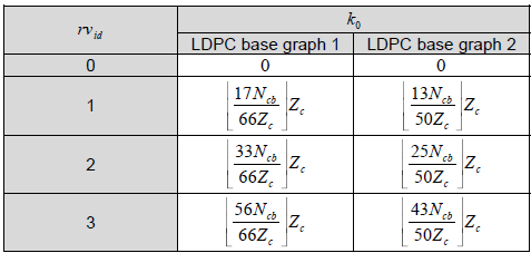
Which rv version is transmitted at each transmission is specified in DCI as shown in the example below.
Message: ss_id=3 cce_index=2 al=2 dci=1_1
Data:
rb_alloc=0x0
mcs1=24
ndi1=1
rv_idx1=0
harq_process=0
dai=0
tpc_command=1
pucch_rsc=0
harq_feedback_timing=3
antenna_ports=0
srs_request=0
dmrs_seq_init=0
Theoretically network can transmit any rv for each transmission, but usually rv sequence is 0->2->3->1. It indicates :
- at 1st transmittion : rv0 is transmitted
- at 2nd transmittion : rv2 is transmitted
- at 3rd transmittion : rv3 is transmitted
- at 4th transmittion : rv1 is transmitted
How many HARQ processor ?
Unlike LTE, in NR the max number of HARQ processor is configurable in RRC message as shown below. If this IE is not configured, it is assumed to be 8.
PDSCH-ServingCellConfig ::= SEQUENCE {
codeBlockGroupTransmission SetupRelease { PDSCH-CodeBlockGroupTransmission } OPTIONAL,
xOverhead ENUMERATED { xOh6, xOh12, xOh18 } OPTIONAL,
nrofHARQ-ProcessesForPDSCH ENUMERATED {n2, n4, n6, n10, n12, n16} OPTIONAL,
pucch-Cell ServCellIndex OPTIONAL, -- Cond SCellAddOnly
[[
maxMIMO-Layers INTEGER (1..8) OPTIONAL, -- Need M
processingType2Enabled BOOLEAN OPTIONAL -- Need M
]]
}
Example 01 >
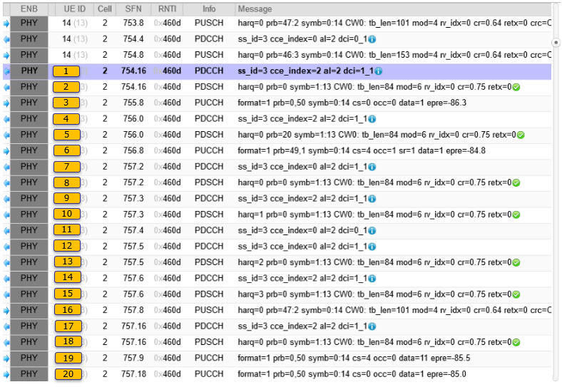
Following is a sample trace log showing sequences of HARQ from Amarisoft.
|
RRC Parameters : In LTE, UE and gNB was able to decode PDSCH and PUSCH purely based on DCI, but in NR to receive PDSCH and PUSCH at proper timing and to get some critical parameters from RRC message that are required for PDSCH/PUSCH decoding. Followings are those parameters in RRC. |
|
tdd-UL-DL-ConfigurationCommon { referenceSubcarrierSpacing kHz30, pattern1 { dl-UL-TransmissionPeriodicity ms5, nrofDownlinkSlots 7, nrofDownlinkSymbols 2, nrofUplinkSlots 2, nrofUplinkSymbols 0 } },
pdsch-ConfigCommon setup: { pdsch-TimeDomainAllocationList { { mappingType typeA, startSymbolAndLength 40 } } } pusch-ConfigCommon setup: { pusch-TimeDomainAllocationList { { k2 4, mappingType typeA, startSymbolAndLength 27 }, { k2 4, mappingType typeA, startSymbolAndLength 27 } },
8, 6, 4, 12 }
pucch-Config setup: { resourceSetToAddModList { { pucch-ResourceSetId 0, resourceList { 0, 1, 2, 3, 4, 5, 6, 7 } }, { pucch-ResourceSetId 1, resourceList { 8, 9, 10, 11, 12, 13, 14, 15 } } }, resourceToAddModList { { startingPRB 0, intraSlotFrequencyHopping enabled, secondHopPRB 50, format format1: { initialCyclicShift 0, nrofSymbols 14, startingSymbolIndex 0, timeDomainOCC 0 } }, { pucch-ResourceId 1, startingPRB 0, intraSlotFrequencyHopping enabled, secondHopPRB 50, format format1: { initialCyclicShift 4, nrofSymbols 14, startingSymbolIndex 0, timeDomainOCC 0 } }, { pucch-ResourceId 2, startingPRB 0, intraSlotFrequencyHopping enabled, secondHopPRB 50, format format1: { initialCyclicShift 8, nrofSymbols 14, startingSymbolIndex 0, timeDomainOCC 0 } }, { pucch-ResourceId 3, startingPRB 0, intraSlotFrequencyHopping enabled, secondHopPRB 50, format format1: { initialCyclicShift 0, nrofSymbols 14, startingSymbolIndex 0, timeDomainOCC 1 } }, { pucch-ResourceId 4, startingPRB 0, intraSlotFrequencyHopping enabled, secondHopPRB 50, format format1: { initialCyclicShift 4, nrofSymbols 14, startingSymbolIndex 0, timeDomainOCC 1 } }, { pucch-ResourceId 5, startingPRB 0, intraSlotFrequencyHopping enabled, secondHopPRB 50, format format1: { initialCyclicShift 8, nrofSymbols 14, startingSymbolIndex 0, timeDomainOCC 1 } }, { pucch-ResourceId 6, startingPRB 0, intraSlotFrequencyHopping enabled, secondHopPRB 50, format format1: { initialCyclicShift 0, nrofSymbols 14, startingSymbolIndex 0, timeDomainOCC 2 } }, { pucch-ResourceId 7, startingPRB 0, intraSlotFrequencyHopping enabled, secondHopPRB 50, format format1: { initialCyclicShift 4, nrofSymbols 14, startingSymbolIndex 0, timeDomainOCC 2 } }, { pucch-ResourceId 8, startingPRB 50, intraSlotFrequencyHopping enabled, secondHopPRB 0, format format4: { nrofSymbols 14, occ-Length n4, occ-Index n0, startingSymbolIndex 0 } }, { pucch-ResourceId 9, startingPRB 50, intraSlotFrequencyHopping enabled, secondHopPRB 0, format format4: { nrofSymbols 14, occ-Length n4, occ-Index n1, startingSymbolIndex 0 } }, { pucch-ResourceId 10, startingPRB 50, intraSlotFrequencyHopping enabled, secondHopPRB 0, format format4: { nrofSymbols 14, occ-Length n4, occ-Index n2, startingSymbolIndex 0 } }, { pucch-ResourceId 11, startingPRB 50, intraSlotFrequencyHopping enabled, secondHopPRB 0, format format4: { nrofSymbols 14, occ-Length n4, occ-Index n3, startingSymbolIndex 0 } }, { pucch-ResourceId 12, startingPRB 1, intraSlotFrequencyHopping enabled, secondHopPRB 49, format format4: { nrofSymbols 14, occ-Length n4, occ-Index n0, startingSymbolIndex 0 } }, { pucch-ResourceId 13, startingPRB 1, intraSlotFrequencyHopping enabled, secondHopPRB 49, format format4: { nrofSymbols 14, occ-Length n4, occ-Index n1, startingSymbolIndex 0 } }, { pucch-ResourceId 14, startingPRB 1, intraSlotFrequencyHopping enabled, secondHopPRB 49, format format4: { nrofSymbols 14, occ-Length n4, occ-Index n2, startingSymbolIndex 0 } }, { pucch-ResourceId 15, startingPRB 1, intraSlotFrequencyHopping enabled, secondHopPRB 49, format format4: { nrofSymbols 14, occ-Length n4, occ-Index n3, startingSymbolIndex 0 } }, { pucch-ResourceId 16, startingPRB 49, intraSlotFrequencyHopping enabled, secondHopPRB 1, format format1: { initialCyclicShift 4, nrofSymbols 14, startingSymbolIndex 0, timeDomainOCC 1 } } }, format1 setup: { }, format4 setup: { maxCodeRate zeroDot25 }, schedulingRequestResourceToAddModList { { schedulingRequestResourceId 1, schedulingRequestID 0, periodicityAndOffset sl40: 8, resource 16 }
pdcch-ConfigCommon setup: { commonControlResourceSet { frequencyDomainResources '111100000000000000000000000000000000000000000'B, duration 1, cce-REG-MappingType nonInterleaved: NULL, precoderGranularity sameAsREG-bundle }, commonSearchSpaceList { { controlResourceSetId 1, monitoringSlotPeriodicityAndOffset sl1: NULL, monitoringSymbolsWithinSlot '10000000000000'B, nrofCandidates { aggregationLevel1 n0, aggregationLevel2 n0, aggregationLevel4 n1, aggregationLevel8 n0, aggregationLevel16 n0 }, searchSpaceType common: { dci-Format0-0-AndFormat1-0 { } } } }, },
pdcch-Config setup: { searchSpacesToAddModList { { controlResourceSetId 1, monitoringSlotPeriodicityAndOffset sl1: NULL, monitoringSymbolsWithinSlot '10000000000000'B, nrofCandidates { aggregationLevel1 n1, aggregationLevel2 n1, aggregationLevel4 n1, aggregationLevel8 n0, aggregationLevel16 n0 }, searchSpaceType ue-Specific: { dci-Formats formats0-0-And-1-0 } }, { controlResourceSetId 1, monitoringSlotPeriodicityAndOffset sl1: NULL, monitoringSymbolsWithinSlot '10000000000000'B, nrofCandidates { aggregationLevel1 n1, aggregationLevel2 n1, aggregationLevel4 n1, aggregationLevel8 n0, aggregationLevel16 n0 }, searchSpaceType ue-Specific: { dci-Formats formats0-1-And-1-1 } } } },
|
To analyze HARQ process, the first thing you need to do is to identify a specific HARQ number and follow through all the steps with the same HARQ process number. In this example, I marked HARQ process number with different color.
| [1] PDCCH - SFN : 754.16 |
From: test.log Info: 192.168.1.41:9001, v2019-05-13 Time: 16:15:50.136 Message: ss_id=3 cce_index=2 al=2 dci=1_1 Data: rb_alloc=0x0 mcs1=24 ndi1=1 rv_idx1=0 harq_process=0 dai=0 tpc_command=1 pucch_rsc=0 // According to RRC, this indicate PUCCH format 1 with the config shown here. harq_feedback_timing=3 // According to dl-DataToUL-ACK, this indicate K1 = 12 antenna_ports=0 srs_request=0 dmrs_seq_init=0 |
|
[2] PDSCH - SFN : 754.16 |
|
From: test.log Info: 192.168.1.41:9001, v2019-05-13 Time: 16:15:50.136 Message: harq=0 prb=0 symb=1:13 CW0: tb_len=84 mod=6 rv_idx=0 cr=0.75 retx=0 |
|
[3] PUCCH - SFN : 755.8 |
|
From: test.log Info: 192.168.1.41:9001, v2019-05-13 Time: 16:15:50.146 Message: format=1 prb=0,50 symb=0:14 cs=0 occ=0 data=1 epre=-86.3 |
|
[4] PDCCH - SFN : 756.0 |
|
From: test.log Info: 192.168.1.41:9001, v2019-05-13 Time: 16:15:50.148 Message: ss_id=3 cce_index=2 al=2 dci=1_1
Data: rb_alloc=0x14 mcs1=24 ndi1=0 rv_idx1=0 harq_process=0 dai=0 tpc_command=1 pucch_rsc=0 // According to RRC, this indicate PUCCH format 1 with the config shown here harq_feedback_timing=0 // According to dl-DataToUL-ACK, this indicate K1 = 8 antenna_ports=0 srs_request=0 dmrs_seq_init=0 |
|
[5] PDSCH - SFN : 756.0 |
|
From: test.log Info: 192.168.1.41:9001, v2019-05-13 Time: 16:15:50.148 Message: harq=0 prb=20 symb=1:13 CW0: tb_len=84 mod=6 rv_idx=0 cr=0.75 retx=0 |
|
[6] PUCCH - SFN : 756.8 |
|
From: test.log Info: 192.168.1.41:9001, v2019-05-13 Time: 16:15:50.156 Message: format=1 prb=49,1 symb=0:14 cs=4 occ=1 sr=1 data=1 epre=-84.8 |
|
[7] PDCCH - SFN : 757.2 |
|
From: test.log Info: 192.168.1.41:9001, v2019-05-13 Time: 16:15:50.159 Message: ss_id=3 cce_index=0 al=2 dci=1_1
Data: rb_alloc=0x0 mcs1=24 ndi1=1 rv_idx1=0 harq_process=0 dai=0 tpc_command=1 pucch_rsc=0 // According to RRC, this indicate PUCCH format 1 with the config shown here harq_feedback_timing=1 // According to dl-DataToUL-ACK, this indicate K1 = 6 antenna_ports=0 srs_request=0 dmrs_seq_init=0 |
|
[8] PDSCH - SFN : 757.2 |
|
From: test.log Info: 192.168.1.41:9001, v2019-05-13 Time: 16:15:50.159 Message: harq=0 prb=0 symb=1:13 CW0: tb_len=84 mod=6 rv_idx=0 cr=0.75 retx=0 |
|
[9] PDCCH - SFN : 757.3 |
|
From: test.log Info: 192.168.1.41:9001, v2019-05-13 Time: 16:15:50.160 Message: ss_id=3 cce_index=2 al=2 dci=1_1
Data: rb_alloc=0x0 mcs1=24 ndi1=1 rv_idx1=0 harq_process=1 dai=0 tpc_command=1 pucch_rsc=0 // According to RRC, this indicate PUCCH format 1 with the config shown here harq_feedback_timing=1 // According to dl-DataToUL-ACK, this indicate K1 = 6 antenna_ports=0 srs_request=0 dmrs_seq_init=0 |
|
[10] PDSCH - SFN : 757.3 |
|
From: test.log Info: 192.168.1.41:9001, v2019-05-13 Time: 16:15:50.160 Message: harq=1 prb=0 symb=1:13 CW0: tb_len=84 mod=6 rv_idx=0 cr=0.75 retx=0 |
|
[11] PDCCH - SFN : 757.4 |
|
From: test.log Info: 192.168.1.41:9001, v2019-05-13 Time: 16:15:50.160 Message: ss_id=3 cce_index=0 al=2 dci=0_1
Data: rb_alloc=0x62 time_domain_rsc=0 mcs=16 ndi=1 rv_idx=0 harq_process=0 dai=0 tpc_command=1 antenna_ports=0 srs_request=0 dmrs_seq_init=0 ul_sch_indicator=1 |
|
[12] PDCCH - SFN : 757.5 |
|
From: test.log Info: 192.168.1.41:9001, v2019-05-13 Time: 16:15:50.161 Message: ss_id=3 cce_index=0 al=2 dci=1_1
Data: rb_alloc=0x0 mcs1=24 ndi1=1 rv_idx1=0 harq_process=2 dai=1 tpc_command=1 pucch_rsc=1 // According to RRC, this indicate PUCCH format 1 with the config shown here harq_feedback_timing=2 // According to dl-DataToUL-ACK, this indicate K1 = 4 antenna_ports=0 srs_request=0 dmrs_seq_init=0 |
|
[13] PDSCH - SFN : 757.5 |
|
From: test.log Info: 192.168.1.41:9001, v2019-05-13 Time: 16:15:50.161 Message: harq=2 prb=0 symb=1:13 CW0: tb_len=84 mod=6 rv_idx=0 cr=0.75 retx=0 |
|
[14] PDCCH - SFN : 757.6 |
|
From: test.log Info: 192.168.1.41:9001, v2019-05-13 Time: 16:15:50.161 Message: ss_id=3 cce_index=2 al=2 dci=1_1
Data: rb_alloc=0x0 mcs1=24 ndi1=1 rv_idx1=0 harq_process=3 dai=0 tpc_command=1 pucch_rsc=0 // According to RRC, this indicate PUCCH format 1 with the config shown here harq_feedback_timing=3 // According to dl-DataToUL-ACK, this indicate K1 = 12 antenna_ports=0 srs_request=0 dmrs_seq_init=0 |
|
[15] PDSCH - SFN : 757.6 |
|
From: test.log Info: 192.168.1.41:9001, v2019-05-13 Time: 16:15:50.161 Message: harq=3 prb=0 symb=1:13 CW0: tb_len=84 mod=6 rv_idx=0 cr=0.75 retx=0 |
|
[16] PUSCH - SFN : 757.8 |
|
From: test.log Info: 192.168.1.41:9001, v2019-05-13 Time: 16:15:50.166 Message: harq=0 prb=47:2 symb=0:14 CW0: tb_len=101 mod=4 rv_idx=0 cr=0.64 retx=0 crc=OK snr=28.8 epre=-83.3 ack=1 |
|
[17] PDSCH - SFN : 757.16 |
|
From: test.log Info: 192.168.1.41:9001, v2019-05-13 Time: 16:15:50.166 Message: ss_id=3 cce_index=2 al=2 dci=1_1
Data: rb_alloc=0x0 mcs1=24 ndi1=0 rv_idx1=0 harq_process=0 dai=0 tpc_command=1 pucch_rsc=0 // According to RRC, this indicate PUCCH format 1 with the config shown here harq_feedback_timing=3 // According to dl-DataToUL-ACK, this indicate K1 = 12 antenna_ports=0 srs_request=0 dmrs_seq_init=0 |
|
[18] PDSCH - SFN : 757.16 |
|
From: test.log Info: 192.168.1.41:9001, v2019-05-13 Time: 16:15:50.166 Message: harq=0 prb=0 symb=1:13 CW0: tb_len=84 mod=6 rv_idx=0 cr=0.75 retx=0 |
|
[19] PUCCH - SFN : 757.9 |
|
From: test.log Info: 192.168.1.41:9001, v2019-05-13 Time: 16:15:50.167 Message: format=1 prb=0,50 symb=0:14 cs=4 occ=0 data=11 epre=-85.5 |
|
[20] PUCCH - SFN : 757.18 |
|
From: test.log Info: 192.168.1.41:9001, v2019-05-13 Time: 16:15:50.171 Message: format=1 prb=0,50 symb=0:14 cs=0 occ=0 data=1 epre=-85.0 |
Reference
- 5G NR HARQ
- 5G NR Hybrid ARQ - Devopedia
- What is ARQ and HARQ? - 5G(NR) Fundamentals
- 5G NR User Plane Protocol , Whats new Over LTE in 5G NR