Matlab Toolbox - 4G/LTE
The PHICH carries the ACK or NACK for an uplink transmission, one bit for each uplink transport block. Many of those bits share the same resource elements, so the PHICH is organised in groups and sequences rather than one channel per UE. This page follows it through ltePHICHInfo, ltePHICH and ltePHICHIndices.
If you don't know what PHICH(Physical Hybrid ARQ Indicator Channel) is, refer to Physical Layer Channel : Downlink : PHICH(Physical Hybrid ARQ Indicator Channel) page first.
Followings are the topics to be covered in this page.
PHICH Parameter Calculation
How much PHICH capacity does a cell have, and how is it set? The UE learns it from the MIB, before it reads any other system information, because it cannot find the PDCCH without knowing which REs the PHICH takes.
The PHICH related paremeter configured by RRC message (MIB in this case) is only two as shown below in MIB,
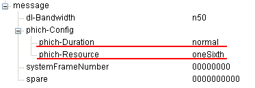
A decoded MIB with dl-Bandwidth n50. The two PHICH fields are phich-Duration = normal and phich-Resource = oneSixth.
In 36.331 v19.3.0, PHICH-Config still has exactly these two fields. The field phich-Duration is normal or extended, and phich-Resource is oneSixth, half, one or two. The toolbox calls them PHICHDuration and Ng.
but many other parameter are derived from that single infomration element in MIB and other indirectly related parameter (like System BW). so it would be helpful to see what kind of intermediate parameters are deribed before we generate physical symbols. This section shows the list of intermediate parameters and their values from eNodeB parameters.
% First you have to define properites of a eNodeB.
% NDLRB indicate System Bandwith in the unit of RBs.
% NDLRB 6 = 1.4 Mhz, NDLRB 15 = 3.0 Mhz, NDLRB 25 = 5.0 Mhz,
% NDLRB 50 = 10 Mhz, NDLRB 75 = 15 Mhz, NDLRB 100 = 20 Mhz
% CellRefP indicate number of downlink Antenna. CellRefP = 1 means 1 transmission antenna (SISO)
% NCellID indicate PCI (Physical Cell Identity) of the Cell
% NSubframe indicate the subframe number.
enb.CyclicPrefix = 'Normal';
enb.PHICHDuration = 'Normal';
enb.Ng = 'One';
enb.NDLRB = 6;
enb.CellRefP = 1;
enb.DuplexMode = 'FDD';
enb.NCellID = 0;
enb.NSubframe = 0;
enb.CFI = 1;
% Once you configured eNB, just pass it to ltePHICHInfo() function and it will give you all the intermediate parameters that are required to generate PHICH symbol and allocate them onto resource grid.
phichInfo = ltePHICHInfo(enb);
Following four examples shows the result by changing only Ng value while keeping every other parameters same. See what has changed in result and see if you can explain to yourself on why you have this kind of result.
|
enb.NDLRB = 6 enb.CellRefP = 1 enb.Ng = 'Sixth' |
enb.NDLRB = 6 enb.CellRefP = 1 enb.Ng = 'Half' |
enb.NDLRB = 6 enb.CellRefP = 1 enb.Ng = 'One' |
enb.NDLRB = 6 enb.CellRefP = 1 enb.Ng = 'Two' |
|
|
NREG: NRE: NPHICH: NGroups: NMappingUnits: NSequences: PHICHDuration: |
3 12 8 1 1 8 1 |
3 12 8 1 1 8 1 |
3 12 8 1 1 8 1 |
6 24 16 2 2 8 1 |
Following four examples shows the result by changing only NDLRB value while keeping every other parameters same. See what has changed in result and see if you can explain to yourself on why you have this kind of result.
|
|
enb.NDLRB = 6 enb.CellRefP = 1 enb.Ng = 'Sixth' |
enb.NDLRB = 25 enb.CellRefP = 1 enb.Ng = 'Sixth' |
enb.NDLRB = 50 enb.CellRefP = 1 enb.Ng = 'Sixth' |
enb.NDLRB = 100 enb.CellRefP = 1 enb.Ng = 'Sixth' |
|
NREG: NRE: NPHICH: NGroups: NMappingUnits: NSequences: PHICHDuration: |
3 12 8 1 1 8 1 |
3 12 8 1 1 8 1 |
6 24 16 2 2 8 1 |
9 36 24 3 3 8 1 |
Following four examples shows the result by changing only CellRefP value while keeping every other parameters same. See what has changed in result and see if you can explain to yourself on why you have this kind of result.
|
enb.NDLRB = 6 enb.CellRefP = 1 enb.Ng = 'Sixth' |
enb.NDLRB = 6 enb.CellRefP = 2 enb.Ng = 'Sixth' |
enb.NDLRB = 6 enb.CellRefP = 3 enb.Ng = 'Sixth' |
enb.NDLRB = 6 enb.CellRefP = 4 enb.Ng = 'Sixth' |
|
|
NREG: NRE: NPHICH: NGroups: NMappingUnits: NSequences: PHICHDuration: |
3 12 8 1 1 8 1 |
3 12 8 1 1 8 1 |
3 12 8 1 1 8 1 |
6 24 16 2 2 8 1 |
The tables follow one formula. For FDD, 36.211 v19.3.0 clause 6.9 gives the number of PHICH groups as NPHICHgroup = ⌈Ng · NRB/8⌉ with the normal cyclic prefix. With NDLRB = 6, only Ng = Two pushes 1.5 up to 2 groups. With Ng = Sixth, 25 RB still gives 1 group, while 50 RB gives 2 and 100 RB gives 3. Every other row follows from the group count: each group has 8 sequences, 3 REGs and 12 REs.
The number of antenna ports does not appear in that formula. So all four CellRefP rows should show the same single group, and the values in the CellRefP table look copied from the Ng table above it. CellRefP = 3 is also not a valid LTE setting, because the cell-specific reference signals exist for 1, 2 or 4 ports only.
NPHICHgroup = ⌈Ng · NRB/8⌉ : for FDD with the normal cyclic prefix.8 sequences per group : with the normal cyclic prefix.3 REGs, 12 REs per group : whatever the bandwidth.CellRefP does not change the group count : the antenna ports change only the precoding.
PHICH Symbol
Once the group and sequence are known, one ACK or NACK bit turns into 12 complex symbols. The plots below show those symbols on four antenna ports, and how they change with the HI value and the sequence index.
This section shows you how you can generate physical symbols for PHICH channel.
% First you have to define properites of a eNodeB.
% NDLRB indicate System Bandwith in the unit of RBs.
% NDLRB 6 = 1.4 Mhz, NDLRB 15 = 3.0 Mhz, NDLRB 25 = 5.0 Mhz,
% NDLRB 50 = 10 Mhz, NDLRB 75 = 15 Mhz, NDLRB 100 = 20 Mhz
% CellRefP indicate number of downlink Antenna. CellRefP = 1 means 1 transmission antenna (SISO)
% NCellID indicate PCI (Physical Cell Identity) of the Cell
% NSubframe indicate the subframe number.
enb.CyclicPrefix = 'Normal';
enb.PHICHDuration = 'Normal';
enb.Ng = 'Sixth';
enb.NDLRB = 6;
enb.CellRefP = 4; % This is the case for 4 Antenna Port. You can set it to be '1' for Single Antenna Case
enb.DuplexMode = 'FDD';
enb.NCellID = 0;
enb.NSubframe = 0;
enb.CFI = 1;
% Since the purpose of PHICH is to transmit 'ACK' or 'NACK' information, you have to configure whether
% you want to send ACK or NACK. Also you have many choce to carry this ACK/NACK information in terms of
% PHICH Group Index and Sequence Number. So you have to configure these values before you generate
% a specific PHICH Symbol sequence.
PHICH_Group_Index = 0;
PHICH_Sequence_Index = 1;
HARQ_Indicator_Value = 0; % 0 = NACK, 1 = ACK
% Once you have configured all the parameters for PHICH, just pass them to the fuction ltePHICH() and it will
% generate the physical symbols. phichSymbol_rows, phichSymbol_cols, phichSymbol_row_index are only for
% plotting (visualization) at later steps.
phichSymbol = ltePHICH(enb,[PHICH_Group_Index,PHICH_Sequence_Index,HARQ_Indicator_Value]);
phichSymbol_rows= length(phichSymbol(:,1));
phichSymbol_cols = length(phichSymbol(1,:));
phichSymbol_row_index = 0:phichSymbol_rows-1;
% Following is to plot the PHICH symbol transmitted by the first antenna port.
subplot(phichSymbol_cols,3,1);
plot(real(phichSymbol(:,1)),imag(phichSymbol(:,1)),'ro','MarkerFaceColor',[1 0 0]);
title('Constellation');
subplot(phichSymbol_cols,3,[2 3]);
plot(phichSymbol_row_index,real(phichSymbol(:,1)),'ro-',phichSymbol_row_index,imag(phichSymbol(:,1)),'bo-');
xlim([0 max(phichSymbol_row_index)]);
title('PHICH index vs PHICH value. Red -> real, Blue -> Imaginary');
% Following is to plot the PHICH symbol transmitted by the second antenna port if it is used.
if enb.CellRefP >= 2
subplot(phichSymbol_cols,3,4);
plot(real(phichSymbol(:,2)),imag(phichSymbol(:,2)),'ro','MarkerFaceColor',[1 0 0]);
title('Constellation');
subplot(phichSymbol_cols,3,[5 6]);
plot(phichSymbol_row_index,real(phichSymbol(:,2)),'ro-',phichSymbol_row_index,imag(phichSymbol(:,2)),'bo-');
xlim([0 max(phichSymbol_row_index)]);
title('PHICH index vs PHICH value. Red -> real, Blue -> Imaginary');
end
% Following is to plot the PHICH symbol transmitted by the third antenna port if it is used
if enb.CellRefP >= 3
subplot(phichSymbol_cols,3,7);
plot(real(phichSymbol(:,3)),imag(phichSymbol(:,3)),'ro','MarkerFaceColor',[1 0 0]);
title('Constellation');
subplot(phichSymbol_cols,3,[8 9]);
plot(phichSymbol_row_index,real(phichSymbol(:,3)),'ro-',phichSymbol_row_index,imag(phichSymbol(:,3)),'bo-');
xlim([0 max(phichSymbol_row_index)]);
title('PHICH index vs PHICH value. Red -> real, Blue -> Imaginary');
end
% Following is to plot the PHICH symbol transmitted by the fourth antenna port if it is used
if enb.CellRefP >= 4
subplot(phichSymbol_cols,3,10);
plot(real(phichSymbol(:,4)),imag(phichSymbol(:,4)),'ro','MarkerFaceColor',[1 0 0]);
title('Constellation');
subplot(phichSymbol_cols,3,[11 12]);
plot(phichSymbol_row_index,real(phichSymbol(:,4)),'ro-',phichSymbol_row_index,imag(phichSymbol(:,4)),'bo-');
xlim([0 max(phichSymbol_row_index)]);
title('PHICH index vs PHICH value. Red -> real, Blue -> Imaginary');
end
Following example shows you four different sequence of PHICH symbols (12 symbols always) on each of the four antenna.
|
PHICH_Group_Index = 0; PHICH_Sequence_Index = 2; HARQ_Indicator_Value = 0; enb.CellRefP = 4 |
If you set enb.CellRefP = 1, you would have only one sequence of data. Ecah of the following sequence will be allocated to each of the four antenna port |
|
|
|
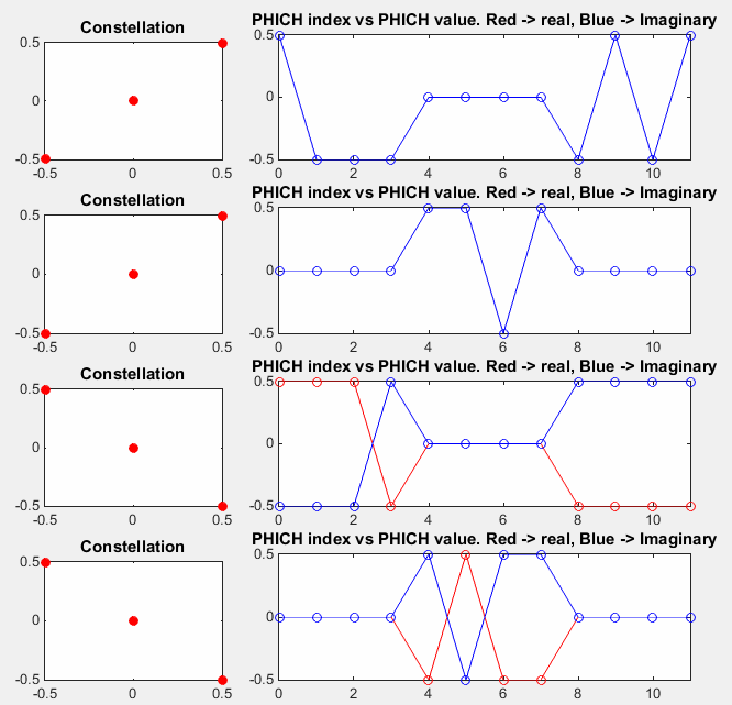
Four antenna ports, one row each. Ports 0 and 2 carry symbols 0 to 3 and 8 to 11, and ports 1 and 3 carry symbols 4 to 7. The other positions are zero.
Following example shows you four different sequence of PHICH symbols (12 symbols always) on each of the four antenna. The only difference from previous example is HARQ_Indicator_Value. Previous is for NACK and this example is for ACK.
|
PHICH_Group_Index = 0; PHICH_Sequence_Index = 2; HARQ_Indicator_Value = 1; enb.CellRefP = 4 |
If you set enb.CellRefP = 1, you would have only one sequence of data. Ecah of the following sequence will be allocated to each of the four antenna port |
|
|
|
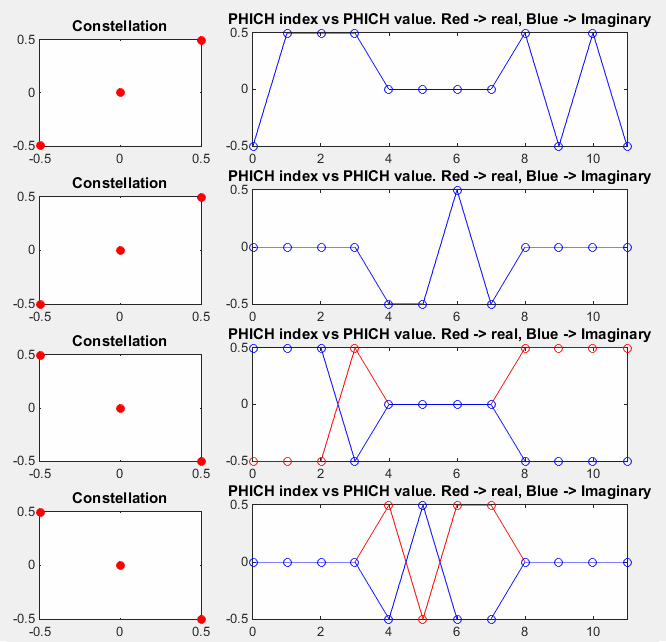
The same group and sequence with an ACK. Every value is the negative of the NACK case.
This example is for PHICH for sending NACK which is similar to the first example. The only difference between this example and the first example is PHICH_Sequence_Index
|
PHICH_Group_Index = 0; PHICH_Sequence_Index = 1; HARQ_Indicator_Value = 0; enb.CellRefP = 4 |
If you set enb.CellRefP = 1, you would have only one sequence of data. Ecah of the following sequence will be allocated to each of the four antenna port |
|
|
|
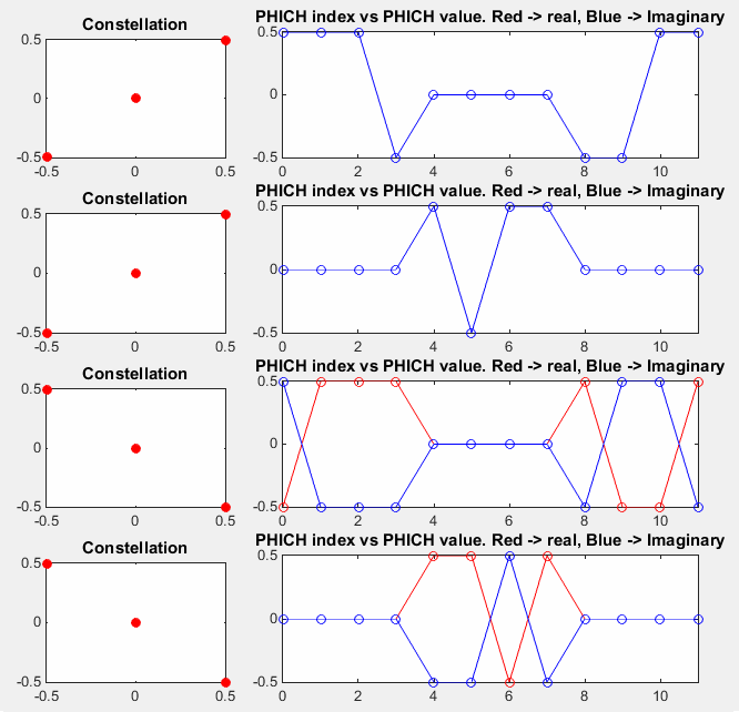
Sequence 1 instead of sequence 2, again with a NACK. A different sequence index gives a different pattern of signs in the same positions.
The 12 symbols come from one HI bit. 36.212 repeats the bit three times, and 36.211 clause 6.9.1 modulates it with BPSK, spreads each symbol with a length-4 orthogonal sequence and scrambles the result. The orthogonal sequence is chosen by the sequence index, so up to 8 PHICHs share the same 12 REs and still stay separable.
With four antenna ports, clause 6.9.2 applies transmit diversity to pairs of ports, and alternates the pairs from one REG to the next. That is why ports 0 and 2 carry 8 of the 12 positions in the plots above, and ports 1 and 3 carry the other 4. The values ±0.5 ± j0.5 on each port reflect the power split between the two ports of a pair.
1 HI bit becomes 12 symbols : 3 repetitions, BPSK, spreading factor 4.ACK and NACK differ only in sign : the ACK plot is the NACK plot negated.Sequence index selects the orthogonal code : up to 8 PHICHs share one group.Four ports alternate in pairs : each port is zero in at least one of the three REGs.
PHICH RE Mapping
The last question is where the 12 PHICH REs sit in the first OFDM symbol. They share that symbol with the RS and the PCFICH, so their position depends on both, as well as on the cell identity.
The last step is to allocate each of the symbols to corresponding Resource Elements and this section shows the matlab code for that process.
% First you have to define properites of a eNodeB.
% NDLRB indicate System Bandwith in the unit of RBs.
% NDLRB 6 = 1.4 Mhz, NDLRB 15 = 3.0 Mhz, NDLRB 25 = 5.0 Mhz,
% NDLRB 50 = 10 Mhz, NDLRB 75 = 15 Mhz, NDLRB 100 = 20 Mhz
% CellRefP indicate number of downlink Antenna. CellRefP = 1 means 1 transmission antenna (SISO)
% NCellID indicate PCI (Physical Cell Identity) of the Cell
% NSubframe indicate the subframe number.
enb.CyclicPrefix = 'Normal';
enb.PHICHDuration = 'Normal';
enb.Ng = 'Sixth';
enb.NDLRB = 6;
enb.CellRefP = 1;
enb.DuplexMode = 'FDD';
enb.NCellID = 0;
enb.NSubframe = 0;
enb.CFI = 1;
% Following is to create an empty resource grid for one subframe.
resourceGrid = lteDLResourceGrid(enb);
% Following is to create symbols for Cell Specific Reference Signal and make a list of resource index for the
% reference signal.
rs_Ant0_sym = lteCellRS(enb,0);
rs_Ant0_sym_ind = lteCellRSIndices(enb,0);
rs_Ant0_arrayIndex = 0:length(rs_Ant0_sym)-1;
% Following is to create symbols for PCFICH and make a list of resource index for the signal
cfi_cw = lteCFI(enb);
pcfich_sym = ltePCFICH(enb,cfi_cw);
pcfich_sym_arrayIndex = 0:length(pcfich_sym)-1;
pcfich_sym_ind = ltePCFICHIndices(enb,{'1based','re'});
phich_sym_ind = ltePHICHIndices(enb,{'1based','re'});
% Following is to create symbols for PSS and make a list of resource index for the signal
pss = ltePSS(enb);
pss_arrayIndex = 0:length(pss)-1;
pss_sym_ind = ltePSSIndices(enb,0,{'1based','re'});
% Following is to create symbols for SSS and make a list of resource index for the signal
sss = lteSSS(enb);
sss_arrayIndex = 0:length(sss)-1;
sss_sym_ind = lteSSSIndices(enb,0,{'1based','re'});
% Following part is filling the resource grid with each of the signal.. but if you see carefully I didn't fill this
% with real symbol number, I just filled it with a constant that I arbitrarily set. This is just for visualization..
% just to allocate constant/outstanding color for each signal. When you use this resource grid for real
% transmission (not for visualization), fill the resourceGrid with real symbol value you generated above.
pss_scale = 0.2;
sss_scale = 0.4;
rs_scale = 1.0;
pcfich_scale = 0.5;
phich_scale = 0.8;
resourceGrid(pss_sym_ind) = pss_scale;
resourceGrid(sss_sym_ind) = sss_scale;
resourceGrid(rs_Ant0_sym_ind) = rs_scale;
resourceGrid(pcfich_sym_ind) = pcfich_scale;
resourceGrid(phich_sym_ind) = phich_scale;
% Following is to display the resource grid. I didn't find any proper functions in the toolbox to display
% one subframe grid as I like. So I used a little bit of tricks. First I plot 3D surface graph with the grid and
% move the view point right on top of the plot so that it looks like plane 2D grid.
xStep = 0:13;
yStep = 0:(enb.NDLRB*12-1);
surface(xStep,yStep,abs(resourceGrid));
axis([0 13 0 (enb.NDLRB*12-1) 0 1]);
view([0,90]);
set(gca,'xtick',[0 6 7 13]);
set(gca,'ytick',[[0:12:enb.NDLRB*12-1] [enb.NDLRB*12-1]]);
Followings are the two example of allocating PHICH for two difference cell configuration. The only difference between the two is NCellID (PCI). The orange color in the symbol 0 represents PHICH. As you see, the number of the orange RE is always 12, but the location changes depending NCellID.
|
enb.NCellID = 0; enb.CellRefP = 1; enb.PHICHDuration = 'Normal'; enb.Ng = 'Sixth'; enb.NDLRB = 6; enb.CFI = 1; |
enb.NCellID = 1; enb.CellRefP = 1; enb.PHICHDuration = 'Normal'; enb.Ng = 'Sixth'; enb.NDLRB = 6; enb.CFI = 1; |
|
|
|
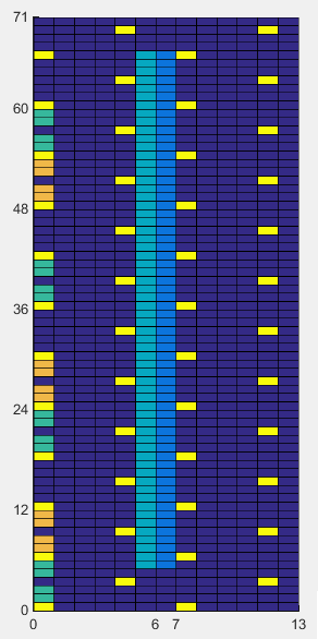
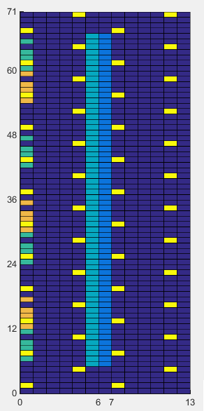
1.4 MHz. The three PHICH REGs, in orange, start at subcarriers 6, 24 and 48 for NCellID 0, and at 12, 30 and 54 for NCellID 1.
Followings are two example of PHICH allocation for the same system bandwidth of 5 Mhz. The only difference between these two examples is Cell ID. The difference between this example and previous example is system bandwidth. The PHICH position is the 'orange' resource elements in the first symbol. If you count the number of orange REs, it is same as in previous example. It means the number of PHICH RE does not change with system BW. But you would notice the gap between each PHICH REG(Resource Element Group) are different from previous example. Basic idea for PHICH resource allocation is to distribute the 3 REGs as evenly as possible accross full system bandwidth.
|
enb.NCellID = 0; enb.CellRefP = 1; enb.PHICHDuration = 'Normal'; enb.Ng = 'Sixth'; enb.NDLRB = 25; enb.CFI = 1; |
enb.NCellID = 1; enb.CellRefP = 1; enb.PHICHDuration = 'Normal'; enb.Ng = 'Sixth'; enb.NDLRB = 25; enb.CFI = 1; |
|
|
|
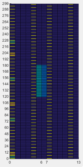
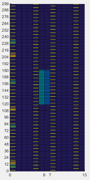
5 MHz. The three PHICH REGs start at subcarriers 6, 102 and 198 for NCellID 0, and at 12, 108 and 204 for NCellID 1.
36.211 clause 6.9.3 places the PHICH after the PCFICH. It numbers only the REGs of symbol 0 that the PCFICH leaves free, n′0 of them. It then puts REG i of the group on free REG number (NIDcell + m′ + ⌊i · n′0/3⌋) mod n′0, where m′ is the mapping unit. With 6 RB, n′0 = 12 - 4 = 8, and for NCellID 0 the free REG numbers are 0, 2 and 5. These fall on subcarriers 6, 24 and 48, as the grid shows.
That is why the PCFICH page comes first. The PHICH position depends on where the PCFICH is, and both depend on the cell identity. The step ⌊i · n′0/3⌋ spreads the three REGs over about a third of the bandwidth each, which gives the PHICH frequency diversity.
REGs counted after the PCFICH : only the free REGs of symbol 0 are numbered.Start set by NCellID : then spaced by about a third of the free REGs.12 REs per group : 3 REGs of 4 REs, as the table in the first section shows.
Disclaimer !
This page is only to show you the overall logics and visualization for various LTE physical layer channels. I haven't investigated much about verifying about the accuracy.
If you think the code is not so efficient, it is 100% my fault. I haven't made any effort for effiecient code. I just tried to create code as simple as possible for the readers. As you know, easy-to-read code is not always efficient for a specific chipset.
If you find any mistake in terms of accuracy, it is also very highly likely be my fault. Not the problem of Matlab tool box itself.
Any comment and corrections if you find any mistake will be welcome and appreciated.
Reference
[1] 3GPP TS 36.211 v19.3.0 - clause 6.9, Physical hybrid ARQ indicator channel
[2] 3GPP TS 36.331 v19.3.0 - PHICH-Config
[3] Physical Layer Channel : Downlink : PHICH