Trigger is a mechanism by which an AP can notify or request various information for station, or most importantly transmit the scheduling information to stations. It is used mostly in OFDMA process. For this purpose, AP transmit a specific MAC frame called Trigger Frame. There are various types of Trigger Frames as listed below.
- Basic Trigger frame
- Beamforming Report Poll (BFRP)
- Multi-user block ack request (MU-BAR)
- Multi-user request to send (MU-RTS)
- Buffer Status Report Poll (BSRP)
- GCR MU-BAR
- Bandwidth Query Report Poll (BQRP)
- NDP Feedback Report Poll (NFRP)
Why does an AP need a special frame for this? In the older 802.11 access, every station contends for the medium on its own, so only one station transmits at a time. Uplink OFDMA in 802.11ax changes that. Several stations transmit at the same moment, each in its own resource unit - RU - and the AP receives all of them as one PPDU. So the stations must start together, end together and reach the AP with a similar power. No station can work this out alone. The Trigger frame fixes the timing, and it gives each station its RU, its MCS and its target power.
Structure of Trigger Frame
The structure of the most common / important Trigger Frame that are used for OFDMA process is shown below. Depending on the purpose of the triggering (e.g, Downlink OFDMA or Uplink OFDMA), some of the fields would be set as 'reserved' (not used).
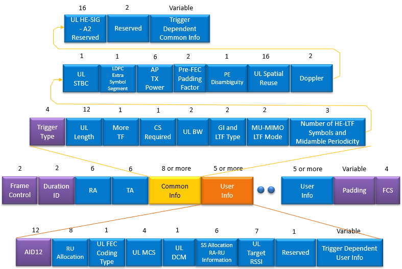
MAC header and FCS : Frame Control, Duration ID, RA and TA take 2 + 2 + 6 + 6 = 16 octets, and the FCS adds 4. TA is the address of the AP. RA is the address of one station, or a broadcast address when the frame addresses several stations.Common Info - 8 octets or more : the part that every addressed station uses. Trigger Type says what kind of response the AP wants. UL Length, UL BW, GI and LTF Type and the number of HE-LTF symbols describe the HE TB PPDU that the stations send back.User Info - 5 octets or more, one per station : AID12 names the station and RU Allocation gives its RU. UL MCS, UL FEC Coding Type and UL DCM set its modulation and coding, and SS Allocation gives its spatial streams. UL Target RSSI says how strong its signal should be at the AP.Trigger Dependent fields : the variable parts at the end of Common Info and of each User Info. Their content depends on Trigger Type. A Basic Trigger has no Trigger Dependent Common Info, but it adds one octet per User Info with MPDU MU Spacing Factor, TID Aggregation Limit and Preferred AC.Padding : extra octets after the last User Info. They give a slow station more time to prepare its response. A User Info position with AID12 = 4095 marks where the padding starts.
One detail in the picture needs a correction. Without its Trigger Dependent part, the Common Info field is 8 octets, which is 64 bits. The bit widths in the two upper rows add up to 74. The Wireshark 802.11 dissector defines MU-MIMO LTF Mode and Doppler as 1 bit each, UL HE-SIG-A2 Reserved as 9 bits and the last Reserved as 1 bit. With those four widths the fields add up to exactly 64 bits. The User Info row in the picture is correct. Its bits add up to 40, which is 5 octets.
The Trigger Type subfield is 4 bits, so it can carry 16 values. Values 0 to 7 are the eight types listed at the top of this page, in the same order. Value 8 is Ranging, which 802.11az added for positioning. The table below lists them with the response each one asks for.
Value |
Trigger Type |
What the addressed stations send back |
0 | Basic | Data frames in an HE TB PPDU |
1 | Beamforming Report Poll | Beamforming feedback after a sounding NDP |
2 | MU-BAR | BlockAck |
3 | MU-RTS | CTS |
4 | BSRP | Buffer status report |
5 | GCR MU-BAR | BlockAck for group addressed traffic |
6 | BQRP | Bandwidth query report |
7 | NFRP | A short NDP, for example as a resource request |
8 | Ranging | Ranging responses, added by 802.11az |
9 - 15 | Reserved | - |
Two fields in the picture work as a pair, and together they set the uplink power. AP TX Power in Common Info tells the stations how strong the AP transmitted the Trigger frame. Its 6-bit value maps to -20 + value dBm, so 0 to 60 covers -20 dBm to +40 dBm. UL Target RSSI in User Info is the power that the AP wants to receive from that station. Its 7-bit value maps 0 to 90 onto -110 dBm to -20 dBm, and the value 127 asks for the maximum transmit power for the assigned MCS.
The station measures the received power of the Trigger frame. The difference from AP TX Power is its path loss. So the station transmits at UL Target RSSI plus that path loss. For example, AP TX Power = 40 means +20 dBm. If the station receives the Trigger frame at -60 dBm, its path loss is 80 dB. With UL Target RSSI = 30, which means -80 dBm, the station transmits at -80 + 80 = 0 dBm. Why does the AP care about this? All RUs arrive in one PPDU, so a strong station next to a weak one can leak into the weak station's RU.
Let's also work out the size of a Basic Trigger frame for four stations. The MAC header takes 16 octets and the Common Info takes 8. Each User Info takes 5 octets plus the 1-octet Basic Trigger Dependent User Info, so four stations need 4 x 6 = 24 octets. The FCS adds 4. The frame is therefore 16 + 8 + 24 + 4 = 52 octets before any padding.
One frame schedules many stations : Common Info holds what the stations share, and one User Info per station holds what differs.AID12 is the key of each User Info : a station reads the User Info with its own AID. The value 4095 ends the list, and the values 0 and 2045 mark RUs for random access.AP TX Power and UL Target RSSI set the uplink power : the station works out its path loss from them, so the AP receives all RUs at a similar level.The picture has four wrong bit widths : Common Info is 64 bits, with 1 bit for MU-MIMO LTF Mode and Doppler, 9 bits for UL HE-SIG-A2 Reserved and 1 reserved bit.
Examples of Triggering
There are many different cases where triggers are used and followings are some of the examples showing how the trigger works. I think the most common use cases for the trigger is OFDMA scheduling process.
Let's follow one uplink OFDMA exchange from start to end, because every field in the structure above has a job in it. The AP first needs to know which stations have data. So it can send a BSRP Trigger frame, and each addressed station answers with a buffer status report. Next the AP sends a Basic Trigger frame. That frame gives each station an RU, an MCS, a target power and the UL Length. SIFS after the end of the Trigger frame, all the addressed stations transmit together in one HE TB PPDU. Finally the AP acknowledges all of them at once with a Multi-STA BlockAck.
The diagram below shows the Basic Trigger part of this exchange for two stations. Time runs from left to right, and each row is one transmitter. The dashed lines mark the two SIFS gaps.
Uplink OFDMA with a Basic Trigger frame. The two stations start and end together, because SIFS fixes the start and UL Length fixes the end.
Common start : each station starts SIFS after the end of the PPDU that carries the Trigger frame. SIFS is 16 microseconds in the 5 GHz and 6 GHz bands.Common end : UL Length sets the duration of the HE TB PPDU. A station with less data fills the rest with padding, so no RU ends early.One acknowledgement for all : the Multi-STA BlockAck carries a separate BlockAck for each station, identified by its AID.CS Required : when this bit is set, a station checks that the medium is idle before it answers. If the medium is busy, the station stays silent instead of colliding.
The other trigger types follow the same pattern, and only the content of the response changes. An MU-RTS gets CTS frames, which protect the rest of the TXOP. An MU-BAR gets BlockAck frames for downlink data. A Beamforming Report Poll follows a sounding NDP, and the stations send back their beamforming feedback. The AP can also chain these exchanges inside one TXOP, and More TF tells the stations that another Trigger frame follows.
The Trigger frame is the uplink grant of 802.11ax : a station in an uplink OFDMA exchange transmits only when a Trigger frame names it.BSRP comes before Basic : the AP asks for buffer status first, then allocates RUs to the stations that have data.Timing is fixed by the AP : SIFS fixes the start of the response and UL Length fixes its end, so all RUs line up in one PPDU.
References
- The MU-RTS/CTS process in the HE (802.11ax) - standard
- Generating the Trigger Frame
- packet-ieee80211.c : Wireshark 802.11 dissector - HE Trigger frame field definitions