ACPR stands for Adjacent Channel Power Ratio and ACLR stands for Adjacent Channel Leakage Ratio. The definition is simple. It is the ratio of power between the main channel and those channels around the main channel as shown below.
Every transmitter leaks a little power outside its own channel. ACLR and ACPR put one number on that leakage, and that number decides whether two systems can sit next to each other in the spectrum. I'll start with how the ratio is written, because two sign conventions are in common use. Then we'll look at why the leakage matters, what causes it, and how it is measured on an LTE signal.
- How Is the Ratio Written?
- Why poor ACLR/ACPR is bad ?
- What causes the poor ACLR/ACPR ?
- ACLR Measurement Example - LTE
- ACLR Measurement Equipment - Spectrum Analyzer
- ACLR Measurement Equipment - Radio Communication Tester
How Is the Ratio Written?
The ratio compares two powers, each measured in its own frequency window. So before reading any ACLR value, you need to know where the windows are and which power sits on top of the fraction.
The spectrum below shows one transmitted channel. The tall block in the centre is the main channel. The shaded bands on each side are the adjacent channels, where the skirts of the main signal still carry some power.
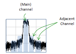
The main channel and its adjacent channels are separate measurement windows. ACLR compares the power inside them.
The main channel holds the wanted signal : its power is integrated over the channel bandwidth only.Each adjacent channel is measured on its own : there is a lower and an upper adjacent channel, and each one gives its own ratio.The skirts are not flat : the leaked power falls off away from the carrier, so the first adjacent channel usually sees more leakage than the second.
The formula below writes the ratio the way this page uses it, with the adjacent channel power on top.
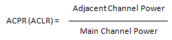
ACPR/ACLR as adjacent channel power over main channel power. In this form the ratio is below 1, so in dB it is a negative number.
3GPP writes the same ratio upside down. TS 36.101 clause 6.6.2.3 defines ACLR as the ratio of the filtered mean power centred on the assigned channel frequency to the filtered mean power centred on an adjacent channel frequency. In that form ACLR is a positive dB value, and the requirement is a minimum, for example 30 dB. Both forms describe the same measurement. Only the sign changes: -30 dB in the form above is 30 dB in the 3GPP form. Many analyzers display the leakage as a negative dB value relative to the carrier, as in the LTE example further down this page.
The less ACLR/ACPR you have, the better it is. Following plot shows two examples showing one good and one poor ACLR/ACPR.
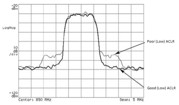
Two transmitters with the same main channel. The one with the raised shoulders leaks more power into the adjacent channels.
The screen is a spectrum analyzer display : the centre is 850 MHz, the span is 5 MHz and the vertical scale is 10 dB per division.The main channel looks identical in both traces : both traces reach the same flat top, so the wanted signal power is the same.The difference is in the shoulders : the grey trace has shoulders about 10 dB above the dark trace on each side of the channel, so its adjacent channel power is higher.Both labels in the plot say Low : the upper arrow should read Poor ACLR and the lower arrow Good ACLR. In the 3GPP form, poor ACLR is the low number. In the adjacent-over-main form of the formula above, poor ACLR is the high number.
As I mentioned above, the definition is simple. More important thing would be why the high ACPR/ACLR is bad and what causes these problems.
Check the convention before comparing numbers : a value of -35 dB and a value of 35 dB can describe the same transmitter.3GPP requirements are minimums : in the 3GPP form, a larger ACLR means less leakage.ACLR is measured in windows : the result depends on the channel bandwidth, the adjacent channel offset and the measurement filter, so these always go with the number.
Why poor ACLR/ACPR is bad ?
Leakage from one transmitter is noise to every receiver tuned to the next channel. So an ACLR limit protects the neighbours more than it protects the transmitter itself. Let's look at the two reasons below, and then at the numbers 3GPP sets for an LTE UE.
: There would be two main reason.
The biggest reason would be that the poor ACPR/ACLR means you have higher unexpected (unwanted) power next to the main channel. What if another communication system is using that adjacent area as a main channel ? In this case, the high adjacent channel power of one communication system become the high interference to another communication system.
There can be another reason. High ACPR/ACLR means that some energy that is supposed to be in main channel spilled over to adjacent channels. It means that the useful energy get lost in useless form and it reduces the efficiency of transmission.
The first reason is the one the requirements are written for. The adjacent channel may belong to another operator, or to another radio technology such as UTRA. The LTE UE requirement therefore covers both cases. TS 36.101 Table 6.6.2.3.1-1 sets E-UTRAACLR1 for an adjacent LTE channel, and Table 6.6.2.3.2-1 sets UTRAACLR1 and UTRAACLR2 for the first and second adjacent UTRA channels. The table below gives the values for a 20 MHz channel. They apply when the measured adjacent channel power is greater than -50 dBm.
Requirement |
Minimum ACLR |
Adjacent channel centre offset |
Adjacent channel filter |
E-UTRAACLR1 |
30 dB |
+/-20 MHz |
Rectangular, 18 MHz |
UTRAACLR1 |
33 dB |
+/-12.5 MHz |
RRC, 3.84 MHz, roll-off 0.22 |
UTRAACLR2 |
36 dB |
+/-17.5 MHz |
RRC, 3.84 MHz, roll-off 0.22 |
The UTRA offsets come from the formulas in the specification. For a 20 MHz channel, UTRAACLR1 sits at 10 + BWUTRA/2 = 12.5 MHz, and UTRAACLR2 at 10 + 3 x BWUTRA/2 = 17.5 MHz, with BWUTRA = 5 MHz. The main channel itself is measured with an 18 MHz rectangular filter.
The second reason needs a number beside it. An ACLR of 30 dB means the adjacent channel holds 10-3, or 0.1 %, of the main channel power. So the energy lost directly into one adjacent channel is small. The larger efficiency cost comes from the fix. To meet the ACLR limit, the power amplifier has to run backed off from compression, and a backed-off amplifier turns less of its DC power into RF.
ACLR limits protect the neighbouring channel : the leaked power becomes interference to a receiver that uses the adjacent channel as its main channel.An LTE UE must meet both LTE and UTRA neighbours : at 20 MHz the limits are 30 dB for E-UTRAACLR1, 33 dB for UTRAACLR1 and 36 dB for UTRAACLR2.The direct energy loss is small : 30 dB of ACLR leaves 0.1 % of the power in each adjacent channel. The efficiency cost comes mainly from the back-off needed to reach that value.
What causes the poor ACLR/ACPR ?
: There can be several factors that would eventually lead to poor ACLR/ACPR. The biggest factor would be non-linearity of power amplifier. (This is why they put a lot of effort to reduce the non-linear effect of a power amplifier).
Let's see why a nonlinear amplifier spreads the spectrum. A modulated signal is a sum of many frequency components inside the channel. A third-order term in the amplifier multiplies three of those components together, and the products land at sums and differences of their frequencies. Many of those products fall outside the channel, up to about one channel bandwidth away on each side. This is the spectral regrowth that raises the shoulders in the traces of the previous section.
The regrowth follows the same rule as a two-tone intermodulation product. When the third-order term dominates, the regrowth rises by 3 dB for each 1 dB rise in the wanted output. So the ratio between the two worsens by about 2 dB for each 1 dB of extra drive, and improves by about 2 dB for each 1 dB of back-off. Near compression this rule stops holding, and the ACLR degrades faster. The 1dB Compression Point page covers that region.
The signal itself sets how hard the problem is. A signal with a high peak-to-average power ratio drives its peaks into compression while its average power is still moderate. LTE handles this at the UE with MPR. TS 36.101 Table 6.2.3-1 lets a power class 1, 2 or 3 UE lower its maximum output power. The allowed reduction is up to 1 dB for QPSK on a wide allocation and up to 2 dB for 16QAM. It rises to 3 dB for 64QAM and 5 dB for 256QAM. Other sources add to the leakage floor as well. Phase noise of the local oscillator widens the carrier skirts, and quantization noise and clipping in the DAC path add noise outside the channel.
Third-order distortion spreads the spectrum by about one channel bandwidth on each side : this is why the first adjacent channel is the one that usually fails.ACLR changes by about 2 dB per dB of drive : this holds while the third-order term dominates, well below compression.MPR trades output power for ACLR : the higher the modulation order and the wider the allocation, the more power reduction the UE is allowed.Back-off, crest factor reduction and digital predistortion are the usual remedies : they either keep the peaks out of compression or correct the amplifier's distortion before it reaches the antenna.
ACLR Measurement Example - LTE
A real measurement puts the definition and the requirement table on one screen. Let's read one from an LTE UE and check it against the limits of the previous sections.
The screen below is the adjacent channel power view of a radio communication tester. The yellow block in the middle is the carrier channel. The yellow blocks on each side are the adjacent E-UTRA channels, and the blue bars inside them are the UTRA channels. The short green lines above each bar are the verdict mask. The table on the right lists the carrier power and the measured value at each adjacent channel offset.
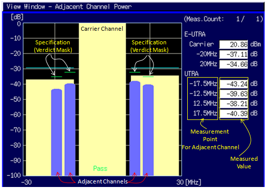
ACLR of a 20 MHz LTE uplink. Every adjacent channel sits below its verdict mask, so the tester reports Pass.
The carrier power is 20.86 dBm : this is the power in the assigned channel, measured with the rectangular filter of the main channel.The E-UTRA results are at -20 MHz and 20 MHz : an adjacent LTE channel at 20 MHz spacing means that the carrier is 20 MHz wide.The UTRA results are at +/-12.5 MHz and +/-17.5 MHz : these are the UTRAACLR1 and UTRAACLR2 offsets for a 20 MHz channel, which confirms the channel bandwidth.The values are shown as negative dB : the tester reports the adjacent channel power relative to the carrier. The 3GPP ACLR is the same value with the sign reversed.
The table below turns the screen values into the 3GPP form and compares them with the limits. The adjacent channel power in dBm is the carrier power plus the displayed dB value. It is well above -50 dBm on every channel, so every requirement applies.
Offset |
Displayed |
Adjacent power |
ACLR, 3GPP form |
Limit |
Margin |
-20 MHz, E-UTRA |
-37.11 dB |
-16.25 dBm |
37.11 dB |
30 dB |
7.11 dB |
+20 MHz, E-UTRA |
-34.66 dB |
-13.80 dBm |
34.66 dB |
30 dB |
4.66 dB |
-17.5 MHz, UTRAACLR2 |
-43.24 dB |
-22.38 dBm |
43.24 dB |
36 dB |
7.24 dB |
-12.5 MHz, UTRAACLR1 |
-39.63 dB |
-18.77 dBm |
39.63 dB |
33 dB |
6.63 dB |
+12.5 MHz, UTRAACLR1 |
-38.21 dB |
-17.35 dBm |
38.21 dB |
33 dB |
5.21 dB |
+17.5 MHz, UTRAACLR2 |
-40.39 dB |
-19.53 dBm |
40.39 dB |
36 dB |
4.39 dB |
The smallest margin is 4.39 dB, at the upper UTRAACLR2 channel. The upper side is worse than the lower side on all three pairs. So the leakage is not symmetric, and both sides have to be checked. The side with the smaller margin is the one to watch when the drive level rises.
The offsets tell you the channel bandwidth : E-UTRA at +/-20 MHz and UTRA at +/-12.5 and +/-17.5 MHz belong to a 20 MHz carrier.Every value passes with at least 4.39 dB to spare : the tightest channel is the upper UTRAACLR2 channel.Adjacent power in dBm checks the -50 dBm condition : the requirement applies only when the adjacent channel power exceeds -50 dBm, and here it is between about -22 dBm and -14 dBm.
ACLR Measurement Equipment - Spectrum Analyzer
A spectrum analyzer, or a signal analyzer, measures ACLR on any signal you connect to it. It needs no knowledge of the protocol. That makes it the usual tool for a power amplifier or a transmitter module on the bench.
The setup below uses one instrument with a built-in signal generator and a signal analyzer. The generator output drives the DUT, and the DUT output returns to the analyzer input. The screen shows the transmitted spectrum with the carrier in the middle and coloured bands marking the measurement windows on each side.
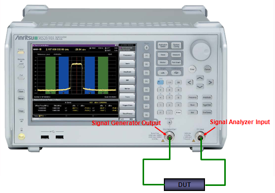
Bench ACLR measurement of a DUT. The generator provides a clean modulated signal, so any leakage the analyzer sees above its own floor comes from the DUT.
Signal Generator Output feeds the DUT : the generator creates the modulated test signal, for example an LTE uplink waveform.Signal Analyzer Input takes the DUT output : the analyzer integrates the power in the main channel window and in each adjacent window.The coloured bands on the screen are the windows : the central band covers the main channel and the bands on each side cover the adjacent channels.
Three settings decide whether the number is right. The first is the filter for each window. For LTE the main and E-UTRA channels use a rectangular filter, while the UTRA channels use an RRC filter with a 0.22 roll-off. The second is the input level. If the level at the analyzer mixer is too high, the analyzer adds its own distortion. If it is too low, the analyzer noise floor fills the adjacent channel. Either way the reading shows the analyzer rather than the DUT. The third is the generator. Its own ACLR has to be well above the DUT's, or the measurement shows the sum of the two.
The analyzer's dynamic range must exceed the DUT's ACLR : set the attenuator and reference level so that neither the analyzer's distortion nor its noise floor reaches the adjacent channel.The filter shape is part of the definition : a rectangular filter and an RRC filter on the same signal give different adjacent channel powers.
ACLR Measurement Equipment - Radio Communication Tester
A radio communication tester measures ACLR on a complete UE rather than on one component. The tester acts as the base station, so the UE transmits a real uplink under the tester's control. This is how a UE is checked against the 3GPP requirements.
The picture below shows a tester with a phone connected to its RF input/output port by a cable. The tester screen shows the same adjacent channel power view that the LTE example above reads in detail.
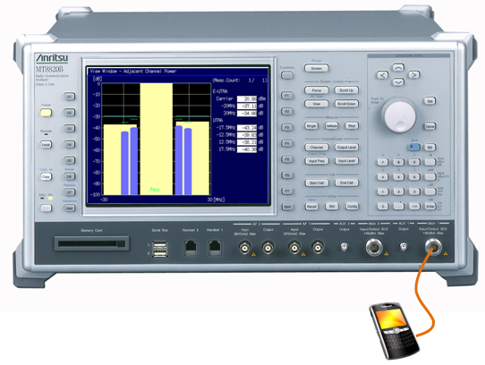
Conducted ACLR measurement of a UE. The same cable carries the downlink to the phone and the uplink back to the tester.
The cable goes to the main RF input/output connector : the tester sends the downlink on it and measures the uplink on the same port.The screen matches the LTE example : carrier power, E-UTRA results at +/-20 MHz and UTRA results at +/-12.5 and +/-17.5 MHz.Pass is shown in green at the bottom of the carrier block : the tester compares each value with the verdict mask and reports one verdict.
The tester controls the conditions that the UE would otherwise choose for itself. It sets up the connection, grants the uplink resource blocks and sends power control commands. That matters for ACLR, because the result depends on the output power, the modulation and the number of resource blocks. The worst case is usually the highest output power, where the PA is closest to compression. So an ACLR check is normally run with the UE at its maximum output power. The allocation matters as well, because the MPR in TS 36.101 depends on the modulation and the number of resource blocks.
A tester measures the whole UE under signalling : the PA, its bias control and the MPR the UE applies are all included in the result.The tester fixes power, modulation and allocation : without that control an ACLR result cannot be compared with the requirement.Bench and tester measurements answer different questions : the analyzer isolates one component, and the tester checks the finished device against 3GPP.