If you are not familiar with details of MAC operation, first refer to Release 8 MAC. In this page, I will post only those features that is new to Release 10. The page has since grown past that, because the same tables and the same control elements kept taking new entries in every release after 10. Everything below is checked against 36.321 v19.3.0.
There is not so much differeces in overal MAC architecture. Even in Carrier Aggregation, still single MAC is used to control/schedule all the carrier components. However, there are a couple of small components newly added to handle the details of new features of LTE Advanced.
Followings are the topics to be described in this page.
- LCID
- MAC CE - Activation/Deactivation MAC Control Element
- MAC CE - Extended Power Headroom
- MAC CE - Timing Advance
- MAC CE - Differential KOffset
- MAC CE - Timing Advance Report
- The MAC CEs added after Release 17
- Reference
LCID
There is one LCID newly added for Downlink and another one for Uplink. In Rel 10 (The first release with Carrier aggregation) the new LCID for downlink is for 'Activation/Deactivation' and the new LCID for uplink is for 'Extended Power Headroom Report'. As LTE Advanced evolves into higher release, we see more and more new items getting added as shown below. Following tables are based on 36.321-6.2.1.
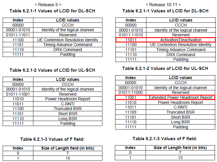
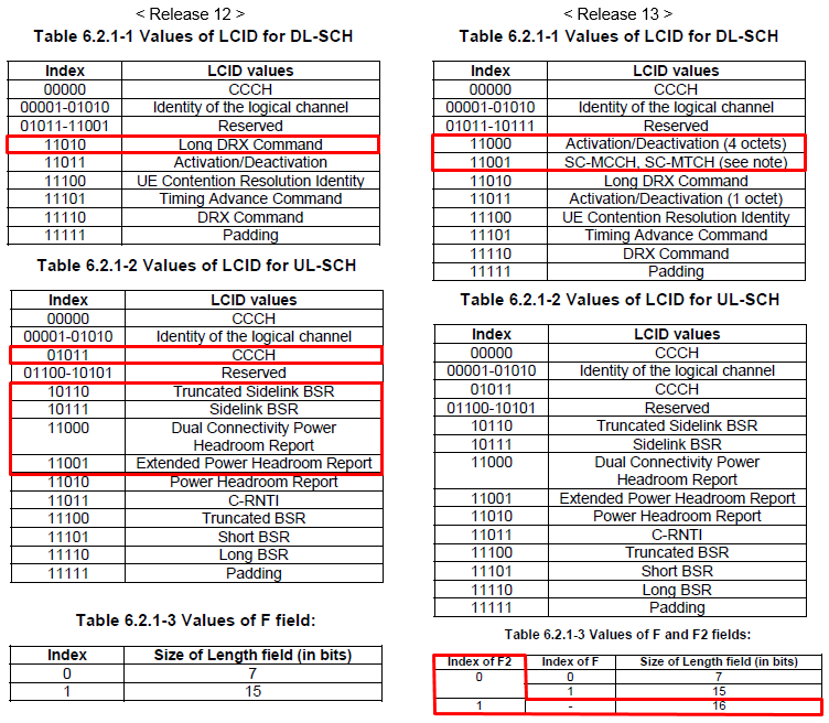
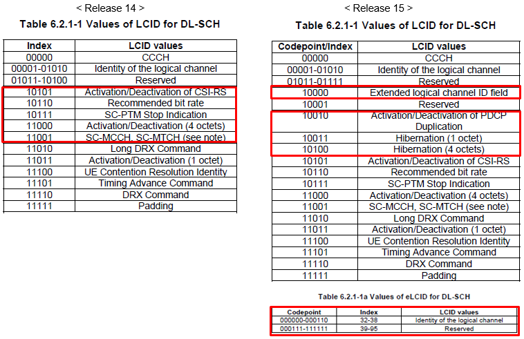
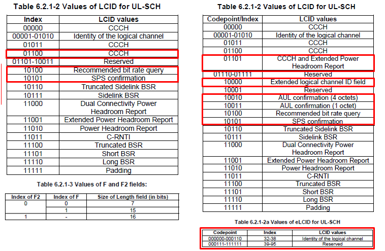
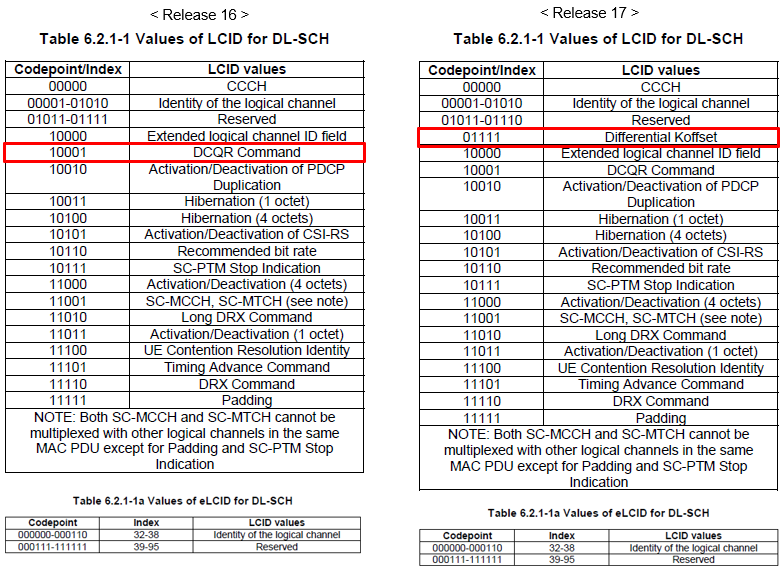
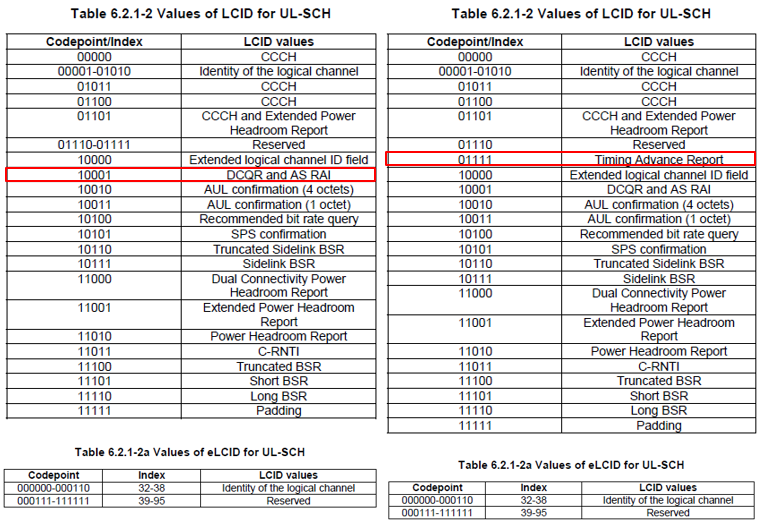
Six pairs of the same two tables, one release against the next. Reading them in order shows where each new entry came from, because every one of them is taken out of the Reserved range.
A new LCID takes a Reserved codepoint : the downlink Reserved range shrinks from 01011-11011 to 01011-11010 when Activation/Deactivation takes 11011, and the uplink range shrinks by one in the same way.Release 10 takes one codepoint each way : 11011 Activation/Deactivation on the downlink and 11001 Extended Power Headroom Report on the uplink, both boxed in red.Release 15 adds an extension field : 10000 becomes Extended logical channel ID field, and Tables 6.2.1-1a and 6.2.1-2a appear underneath to hold the codepoints it reaches.Release 17 adds one entry each way : 01111 Differential Koffset on the downlink and 01111 Timing Advance Report on the uplink, which are the two sections further down this page.The tables are read from the bottom : Padding stays at 11111 in every release, and the new entries are added above it in falling codepoint order.
Three more entries have been taken since the Release 17 tables above. 36.321 v19.3.0 gives the downlink 01101 to UL Transmission Extension Update and 01110 to GNSS Measurement Command, which leaves Reserved at 01011-01100. The uplink gives 01110 to GNSS Validity Duration Report and has no Reserved range left between CCCH and Padding at all.
The extension has nothing behind it yet. Tables 6.2.1-1a and 6.2.1-2a both read 000000-000110 for indices 32 to 38 as Identity of the logical channel, and 000111-111111 for indices 39 to 95 as Reserved. So the extended field currently buys seven more logical channels and nothing else.
Now let's look into those MAC CEs newly added to LTE Advanced.
First refer to LTE MAC pages for release 8 MAC CE to understand general MAC CE. Here I only post the MAC CE that is added only LTE Advanced.
MAC CE - Activation/Deactivation MAC Control Element
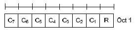
Refer to 36.321 6.1.3.8 Activation/Deactivation MAC Control Element if you want to have formal description. The field structure is as shown below. There are two of them rather than one. The choice depends on the largest serving cell index in the configuration, not on the release the UE is running.
< 36.321 Rel 10,11,12 - Figure 6.1.3.8-1: Activation/Deactivation MAC control element >
From Rel 13, UE Category 17 is added. Based Category 17, we can achieve 32 CC Carrier Aggregation and 25 Gbps. To support 32 CC (31 SCC), a new Activation/Deactivation MAC CE is added as shown below.
< 36.321 Rel 13 - Figure 6.1.3.8-2: Activation/Deactivation MAC control element of four octets >
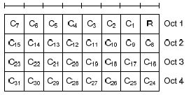
36.321 states the choice between the two layouts in one sentence. For the case with no serving cell with a ServCellIndex larger than 7, the Activation/Deactivation MAC control element of one octet is applied, and otherwise the four octet one. So a UE with two secondary cells indexed 1 and 2 keeps the one octet element, and a UE with a single secondary cell indexed 9 does not.
The octet counts also explain the odd field totals. One octet holds seven C-fields and one R. Four octets hold 31 C-fields and one R, because the reserved bit appears once in the first octet and is not repeated. That is why the ceiling is 31 secondary cells and not 32.
Now the question is to figure out what does C1, C2, C3 etc mean ? Does it automatically mean C1 = SCC1, C2 = SCC2 etc ?
No.. the mapping between C1, C2,..,C7 and SCC1,SCC2,...,SCC7 is defined in RRC Connection Reconfig message. One example is as follows : (In example, sCellIndex-r10 for SCC1 (the first SCC) is set to be 2. It means C2 field in MAC CE is mapped to SCC1. Therefore, in this case 00000100 means that the first SCC shall be activated. This mean that absolution bit position in MAC CE does not specify whether it is for SCC1 or SCC2 etc. The meaning of each bit in MAC is indicated by RRC message. It means what is important is the matching between sCellIndex-r10 and MAC CE bit position. I hope following illustration would sound clearer to you.
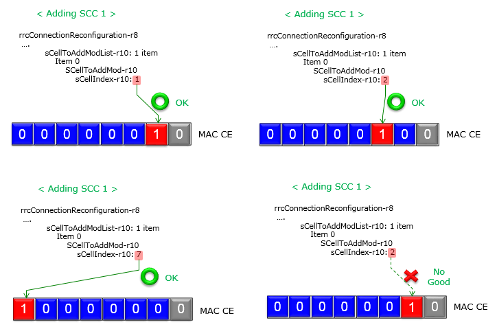
The same secondary cell added four times with a different sCellIndex-r10 each time. Three of the four are marked OK and the fourth is not, and the index is the only thing that changes.
The index picks the bit, not the order of addition : all four panels are captioned Adding SCC 1, and the bit that goes to 1 moves with sCellIndex-r10 rather than staying put.Index 1 sets the bit next to the reserved one : the grey square on the right is R, and C1 sits immediately left of it.Index 7 sets the leftmost bit : C7 is the far end of the octet, and the arrow in the lower left panel runs the whole width of the drawing to reach it.The lower right panel is the mistake : sCellIndex-r10 reads 2 while C1 is set, and the red cross and the No Good label mark it.36.321 says the same thing in one line : the Ci field indicates the status of the SCell with SCellIndex i, and the MAC entity ignores it when no such SCell is configured.
Following is an example of RRC Connection Reconfiguration message to add SCC1.
RRC Connection Reconfiguration adding the first secondary cell, decoded as a tree,
rrcConnectionReconfiguration-r8
    radioResourceConfigDedicated
        physicalConfigDedicated
            pucch-ConfigDedicated-v1020
                pucch-Format-r10: channelSelection-r10 (1)
                    channelSelection-r10
                        n1PUCCH-AN-CS-r10: setup (1)
                            setup
                                n1PUCCH-AN-CS-List-r10: 2 items
                            Item 0
                                        N1PUCCH-AN-CS-r10: 4 items
                                            Item 0
                                                N1PUCCH-AN-CS-r10 item: 361
                                            Item 1
                                                N1PUCCH-AN-CS-r10 item: 362
                                            Item 2
                                                N1PUCCH-AN-CS-r10 item: 363
                                            Item 3
                                                N1PUCCH-AN-CS-r10 item: 364
                                    Item 1
                                        N1PUCCH-AN-CS-r10: 4 items
                                            Item 0
                                                N1PUCCH-AN-CS-r10 item: 365
                                            Item 1
                                                N1PUCCH-AN-CS-r10 item: 366
                                            Item 2
                                                N1PUCCH-AN-CS-r10 item: 367
                                            Item 3
                                                N1PUCCH-AN-CS-r10 item: 368
    nonCriticalExtension
        nonCriticalExtension
            nonCriticalExtension
                sCellToAddModList-r10: 1 item
                    Item 0
            SCellToAddMod-r10
                            sCellIndex-r10: 2
                            cellIdentification-r10
                                physCellId-r10: 1
                                dl-CarrierFreq-r10: 3100
                            radioResourceConfigCommonSCell-r10
                                nonUL-Configuration-r10
                                    dl-Bandwidth-r10: n50 (3)
                                    antennaInfoCommon-r10
                                        antennaPortsCount: an1 (0)
                                    phich-Config-r10
                                        phich-Duration: normal (0)
                                        phich-Resource: one (2)
                                    pdsch-ConfigCommon-r10
                                        referenceSignalPower: 18dBm
                                        p-b: 0
                            radioResourceConfigDedicatedSCell-r10
                                physicalConfigDedicatedSCell-r10
                                    nonUL-Configuration-r10
                                        antennaInfo-r10
                                            transmissionMode-r10: tm1 (0)
                                            ue-TransmitAntennaSelection: release (0)
                                                release: NULL
                                        pdsch-ConfigDedicated-r10
                                            p-a: dB0 (4)
                                    ul-Configuration-r10
                                        cqi-ReportConfigSCell-r10
                                            nomPDSCH-RS-EPRE-Offset-r10: 0dB (0)
                                            cqi-ReportPeriodicSCell-r10: release (0)
                                                release: NULL
The red line reads sCellIndex-r10: 2, so in this capture the second bit from the right of the MAC CE is the one that activates this cell. Nothing else in the message says which bit to use, and the MAC CE itself carries no cell identity. The two have to be read together.
Two layouts, one rule : one octet until a ServCellIndex above 7 appears in the configuration, four octets after that.31 cells, not 32 : the reserved bit appears once, so four octets hold 31 C-fields.The bit position is signalled, not implied : sCellIndex-r10 in RRC decides which Ci belongs to which secondary cell.An unconfigured Ci is ignored : 36.321 tells the MAC entity to ignore a C-field with no SCell behind it rather than to treat it as an error.
MAC CE - Extended Power Headroom
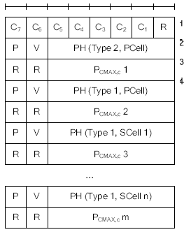
The functionality of Extended Power Headroom is same as Power Headroom MAC CE. The main difference is that Extended Power Headroom can report multiple power headroom value simultaneously. Each of these multiple value is mapped to each component carrier. You will see this part evolves as LTE Advanced release evolves.
< 36.321 Rel 10,11,12 - Figure 6.1.3.6a-2: Extended Power Headroom MAC Control Element >
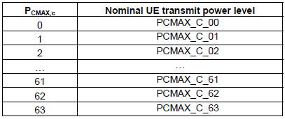
< 36.321 Rel 10,11,12 - Table 6.1.3.6a-1: Nominal UE transmit power level for Extended PHR >
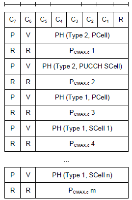
< 36.321 Rel 13 - Figure 6.1.3.6a1-3: Extended PHR MAC Control Element supporting PUCCH on SCell >
< 36.321 Rel 13 - Figure 6.1.3.6a2-4: Extended PHR MAC Control Element supporting 32 serving cells with configured
uplink >
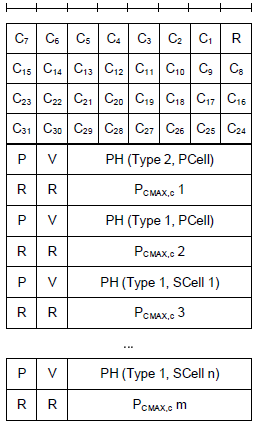
< 36.321 Rel 13 - Figure 6.1.3.6a3-5: Extended PHR MAC Control Element supporting 32 serving cells with configured
uplink and PUCCH on SCell >
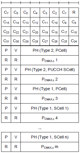
Four figures cover this one control element, and the numbering has a gap that is worth explaining before it puzzles anyone. 36.321 marks Figure 6.1.3.6a-1 as Void, so the run starts at 6.1.3.6a-2 and the later ones carry a second number in the clause part: 6a1-3, 6a2-4 and 6a3-5.
The figure that applies depends on two things. One is whether PUCCH is configured on a secondary cell, which inserts a PH row of Type 2 for that cell. The other is whether the C-field block is one octet or four, which follows the same 32 serving cell question as the Activation/Deactivation element above. The four figures are the four combinations.
The field letters are worth reading too. Ci says a PH field for the SCell with SCellIndex i is present, so the C-field block is a presence map rather than an activation map here. V says whether the PH value came from a real transmission or from a reference format. P says the UE applied power backoff for power management. Each PH field is six bits, and the PCMAX,c octet under it is read through Table 6.1.3.6a-1 shown above.
Which set of figures a UE uses is configured rather than negotiated. 36.321 splits the clause between extendedPHR and extendedPHR2, and only the second reaches the layouts with four octets of C-fields.
Figure 6.1.3.6a-1 is Void : the numbering starts at 6a-2, which is why the sequence looks like it is missing its first entry.Ci is a presence map here : it says a PH field for that SCell follows, not that the cell is activated.A PUCCH SCell adds a Type 2 row : the two figures that carry PH Type 2, PUCCH SCell are the ones for that case.PH is six bits and PCMAX,c is its own octet : Table 6.1.3.6a-1 maps PCMAX,c values 0 to 63 onto PCMAX_C_00 to PCMAX_C_63.extendedPHR2 is the one that reaches 32 cells : 36.321 splits the clause by which of the two is configured.
MAC CE - Timing Advance
As you see in the following figures, for Rel 8,9,10 there is no special tag for each component carrier, meaning that even in Carrier Aggregation single Timing Advanced value apply to all the component carriers. But in Rel 11, the first 2 bits are allocated to indicate whether the value is for PCC or SCC. If TAG id is 0, it means it is for PCC.
< 36.321 Rel 8,9,10 - Figure 6.1.3.5-1: Timing Advance Command MAC control element >

< 36.321 Rel 11 - Figure 6.1.3.5-1: Timing Advance Command MAC control element >

The two reserved bits became the TAG Id, and 36.321 fixes one of its four values. The TAG containing the SpCell has the TAG Identity 0, so a UE never has to be told which group its primary cell belongs to. Two bits then leave three more groups for secondary cells that need a timing advance of their own.
The rest of the octet is unchanged across every release shown. The Timing Advance Command field is six bits and carries an index of 0 to 63, which 36.213 turns into an amount of timing adjustment. Widening the element was never on the table; the TAG Id was carved out of the bits that were already there.
The bits were already there : Release 11 used the two reserved bits rather than adding an octet.TAG Identity 0 is the primary group : 36.321 assigns it to the TAG containing the SpCell.Four groups in total : two bits give TAG Identity 0 to 3, so three secondary groups sit beside the primary one.The command itself did not change : six bits, index 0 to 63, in Release 8 and in Release 19 alike.
MAC CE - Differential KOffset
This one is not a carrier aggregation feature at all. It arrived with Release 17 for non-terrestrial networks. There the round trip to the satellite changes enough during a connection that one broadcast scheduling offset no longer fits every UE.
< 36.321 Rel 17 - Figure 6.1.3.21-1: Differential Koffset MAC CE >
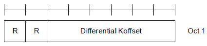
The element is the smallest shape a MAC CE can take that still carries a value. 36.321 clause 6.1.3.21 gives it a fixed size of one octet, two reserved bits set to 0, and a Differential Koffset field of six bits. The field indicates the differential Koffset in subframes, and 36.213 defines what the receiver does with it.
The word differential carries the meaning. The cell broadcasts a common Koffset, and this element adjusts it for one UE rather than replacing it. That is why six bits are enough for a value counted in subframes on a satellite link.
It travels on the downlink. 36.321 says the element is identified by a MAC subheader with an LCID from Table 6.2.1-1, and the Release 17 extract further up this page shows that codepoint as 01111.
One octet, six bits of value : two reserved bits and a six bit Differential Koffset field, per 36.321 clause 6.1.3.21.Downlink only : its LCID comes from Table 6.2.1-1, and Release 17 put it at 01111.It adjusts rather than replaces : the value is differential against the Koffset the cell already broadcast.The unit is subframes : 36.321 names the unit and leaves the use of the value to 36.213.
MAC CE - Timing Advance Report
The element above lets the network correct a UE. This one sends information the other way. It is the uplink half of the same Release 17 work. On a satellite link the UE knows its own timing advance better than the eNB can infer it.
< 36.321 Rel 17 - Figure 6.1.3.20-1: Timing Advance MAC CE >
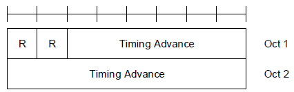
The shape is unusual for a MAC CE. 36.321 clause 6.1.3.20 fixes it at two octets, and the Timing Advance field is 14 bits, with two reserved bits ahead of it. The field indicates the least integer number of subframes greater than or equal to the Timing Advance value. What is reported is therefore a rounded-up subframe count, not the raw value.
The element exists for those fourteen bits. The Timing Advance Command element above it on this page carries six, which is enough for a terrestrial cell and nowhere near enough for the propagation delay to a satellite.
Three events trigger a report, and 36.321 clause 5.4.9 lists all three. Upper layers can instruct one. Configuring offsetThresholdTA triggers one when the UE has not yet reported to this serving cell. A variation from the last report equal to or larger than offsetThresholdTA triggers one as well. The third is the one that runs during a connection, and the threshold is what keeps it from reporting constantly.
Two rules limit how often a report goes out. A MAC PDU shall contain at most one Timing Advance Report MAC CE, even when several events triggered one. The element is built from the latest estimate available just before the PDU is assembled. Every triggered report is cancelled once one is included.
Two octets, 14 bits of value : 36.321 clause 6.1.3.20 fixes the size, and the field spans both octets.The value is a rounded subframe count : the least integer number of subframes greater than or equal to the timing advance.offsetThresholdTA drives the repeat reports : a variation of that size or more since the last report triggers a new one.One report per MAC PDU : several triggers collapse into a single element built from the latest estimate.Uplink only : its LCID comes from Table 6.2.1-2, and Release 17 put it at 01111.
The MAC CEs added after Release 17
Two of the sections above arrived with Release 17 and neither is about carrier aggregation. The same work added three more control elements after them. All three exist to keep a non-terrestrial link aligned, so they are easier to read as a group.
The problem they answer is that a UE talking to a satellite has to know where the satellite is. It gets that from GNSS, and a GNSS fix costs time and goes stale. Two of the three elements are about buying that time and reporting how much of it is left.
GNSS Measurement Command travels on the downlink. 36.321 clause 6.1.3.22 gives it one octet holding a T flag, a reserved bit and a four bit GNSS Measurement Gap Length. The T flag separates a network instruction to measure now from a gap length supplied for the UE to measure on its own. Table 6.1.3.22-1 reads 1 to 7 seconds for codepoints 0000 to 0110, then jumps to 13, 19, 25 and 31 seconds, and reserves 1011 to 1111.
GNSS Validity Duration Report travels back on the uplink. 36.321 clause 6.1.3.23 gives it one octet carrying the remaining validity duration of the UE's fix. Clause 5.4.10 shows how seriously the procedure treats a stale fix. On an indication from upper layers the MAC entity stops the timeAlignmentTimer for the primary timing advance group, then starts a random access procedure.
UL Transmission Extension Update is the unusual one. 36.321 clause 6.1.3.24 gives it a fixed size of zero bits. The whole message is its own subheader, so the LCID codepoint is the message and the element carries no payload at all.
All three took codepoints the Release 17 tables above still show as Reserved. The downlink gave 01101 to UL Transmission Extension Update and 01110 to GNSS Measurement Command. The uplink gave 01110 to GNSS Validity Duration Report, which used the last free codepoint it had.
All three are non-terrestrial : 36.321 clauses 5.4.9 and 5.4.10 name the non-terrestrial network as the reason for the reporting procedures.GNSS Measurement Command sets a gap : four bits give 1 to 7, 13, 19, 25 and 31 seconds, with 1011 to 1111 reserved.A stale fix ends the timing alignment : clause 5.4.10 stops the pTAG timeAlignmentTimer and starts random access.A MAC CE can be empty : UL Transmission Extension Update has a fixed size of zero bits, so its subheader is the whole message.The uplink table is now full : after GNSS Validity Duration Report took 01110 there is no Reserved range left in Table 6.2.1-2.
Reference
One specification carries every field layout, every LCID codepoint and every trigger quoted on this page. The clause numbers above are all from it, and the version below is the one they were read in.
- [1] 36.321 : 3GPP - E-UTRA; Medium Access Control protocol specification, v19.3.0. Clause 6.1.3 holds the MAC control elements, clause 6.2.1 holds the LCID tables, and clauses 5.4.9 and 5.4.10 hold the two non-terrestrial reporting procedures.
- [2] MAC : the Release 8 MAC page on this site, which the introduction above points at.
- [3] MAC CE : the Release 8 MAC control elements, which this page builds on.