|
4G/LTE - Transmission Mode |
||||||||||||||||||||||||||||||||||||||||||||||||||||||||||||||||||||||||||||
|
In LTE, usually they use multiple Antenna for downlink (at least from Category 3 UE and higher), meaning that eNode (Network) has use multiple Tx Antenna and UE use multiple Rx antenna. Now you almost automatically think about 'MIMO', but in reality 'multiple antenna' does not automatically mean 'MIMO'. For example, you have two downlink antenna. You can use these two antenna in various ways. Of course, one ways is to use it as 2 x 2 MIMO, but this is not the only way. You can use the two antenna in diversity configuration rather than MIMO configuration. Or you can just use only one of the antenna and sometimes you would like to use various different multiplexing, precoding methods etc.
In LTE, they give a special name for each of the way of transmission and it is called 'Transmission Mode'. For example, what we normally call 'SISO' (Single Transmission Antenna and Single Reciever Antenna) is called 'TM1(Transmission Mode 1)'. What we normally call 'Diversity' is called 'TM2'. What we call 'MIMO' but no feedback from UE is called 'TM3'. MIMO and UE feedback from UE (CQI, PMI, RI) is called 'TM4'.
NOTE : Regarding how each of various transmission mode is utilized in different situations and how they are configured in signaling message, check out this tutorial of Amarisoft TechAcademy.
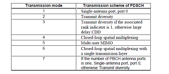
A good summary of each Transmission Mode can be as following table from 36.213. These table ecolved and got more complicated as LTE evolves. I have listed tables from different releases for comparison.
< 36.213-Table 7.2.3-0 : PDSCH transmission scheme assumed for CQI reference resource - Rel 8 >
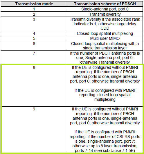
< 36.213-Table 7.2.3-0 : PDSCH transmission scheme assumed for CQI reference resource - Rel 10 >
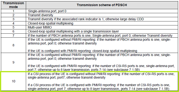
< 36.213-Table 7.2.3-0 : PDSCH transmission scheme assumed for CQI reference resource - Rel 12 >
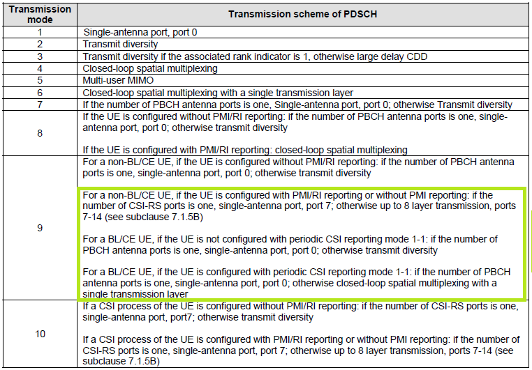
< 36.213-Table 7.2.3-0 : PDSCH transmission scheme assumed for CQI reference resource - Rel 13 >
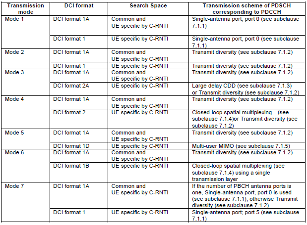
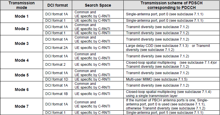
Considering these various possibilities, 3GPP provides several predefined transmission methods and this transmission method is called 'Transmission Mode'. For now, there are seven predefined predefined transmission mode as shown in the following table (TS 36.213)
< 36.213 - Table 7.1-5 : PDCCH and PDSCH configured by C-RNTI - Rel 8>
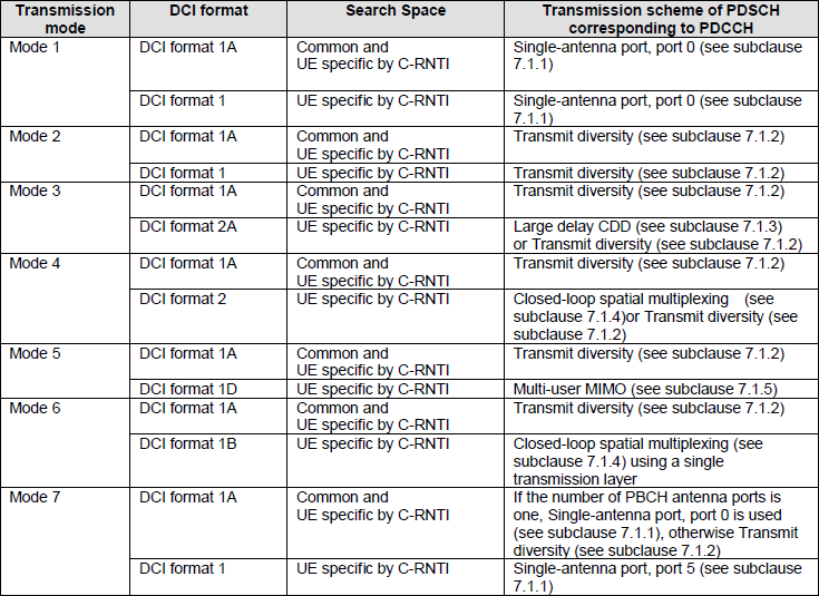
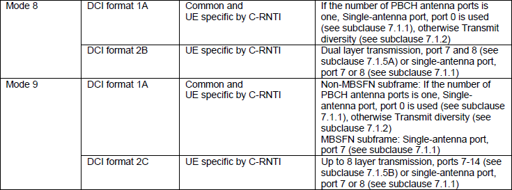
< 36.213 - Table 7.1-5 : PDCCH and PDSCH configured by C-RNTI - Rel 10>
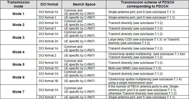
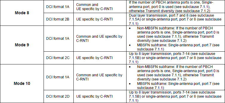
< 36.213 - Table 7.1-5 : PDCCH and PDSCH configured by C-RNTI - Rel 12>
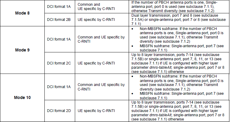
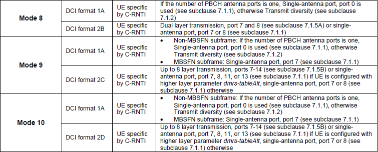
< 36.213 - Table 7.1-5 : PDCCH and PDSCH configured by C-RNTI - Rel 13>
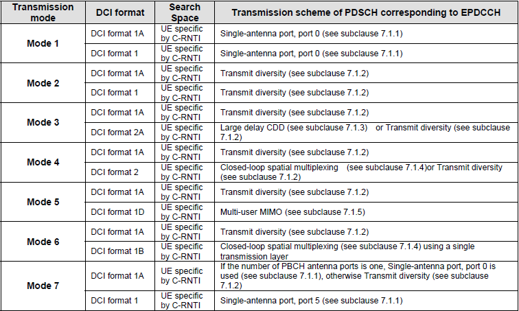
< 36.213 - Table 7.1-5A: EPDCCH and PDSCH configured by C-RNTI - Rel 13>
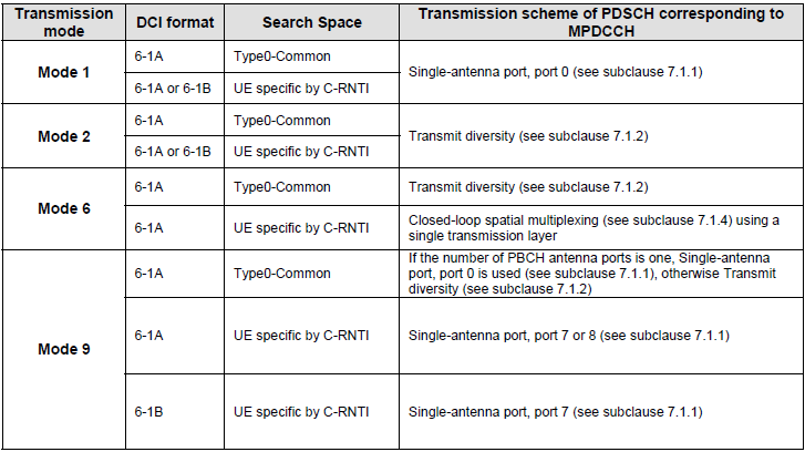
With LTE M1 (BL/CE) in Rel 13, a new table was added as follows.
< 36.213 - Table 7.1-5A: EPDCCH and PDSCH configured by C-RNTI - Rel 13>
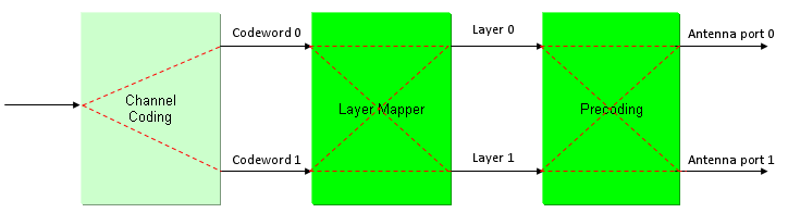
To understand very details of each transmission mode requires almost complete knowledge of physical layer processing. Three important blocks in physical layer to determin the transmission mode can be illustrated as follows. You will find many different ways from the data input (left most arrow) through the final antenna ports (rightmost arrows). Each transmission mode determin which path the input data should follow through.
Some important parameter sets for each transmission mode are as follows. (To understad this process in detail, it is crucial to understand details of Precoding in basic procedure page).
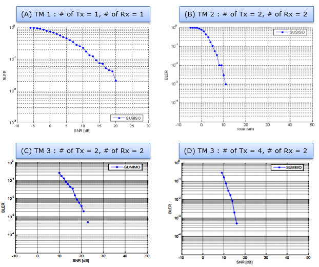
Transmission Mode and BLER
There are various purpose (reasons) for each different Transmission Mode. Some TM is designed mainly to increase throughput, some are to increase communication reliability and some are to handle multiple users simultaneously etc. In this section, I would show you some examples showing the increased communication reliability with a couple of different Transmission Mode. Followings are four plots from Ref [4]. First compare (A) with (B). In terms of throughput, they (TM1 and TM2) are same. But you see much higher performance in terms of BLER measurement in TM2. This would match the common sense that you have. The major purpose of Diversity is to achieve more robust data decoding and decrease error rate (If you are not familiar with interpreting this kind of graph, refer to SNR page. In terms of interpreting the general meaning of the graph, you will get some insight from the interpretation of SNR vs BER graph). Then, Compare (A) and (C), i.e, compare TM1 (SISO) and TM3(MIMO). The major purpose of MIMO is to increase the throughput (but throughput part is not shown in this graph). However, you would see much increased error rate in (C). Note : Be careful, the range of horizontal axis of (A) is different from other three graphs. So it may be a little confusing. Then compare (C) and (D). In this case, Transmission Mode are same, but the antenna configuration is different. (C) is 2x2 MIMO and (D) is 4x2 MIMO. At very high level view, 4x2 is a kind of diversity for 2x2. Accordingly, you will see lower error rate (Diversity gain) in (D) comparing to (C).
Example 1 > Transmission Mode changes while driving in live network
When a UE drive through multiple different networks (e.g, during driving test), it may experience various transmission mode. Let's take a look at a measurement done by a UE in the field. Following plot is from the data captured by a drive test tool Azenqos Drive Test tool (AZQ Android). I got the log captured by the tool and exported the data as csv file and then plot it on Microsoft Excel and figured out the transmission mode setting based on RRC Connection Configuration message that are captured by the same tool. It is almost impossible to correlate the transmission mode and throughput performance just from the following plot because there are so many factors are involved. My intention is to show you how dynamically the transmission mode changes in the live network.
Transmission Mode and Reference Signal (Antenna Ports)
One of the confusing but important thing about transmission mode is to understand the relationship between each transmissiom mode and reference signal (antenna ports). For this, refer to Reference Signal (Antenna Port Number) vs Transmission Mode in Reference Signal (Downlink) page.
References :
Here goes some additional material to read from LteUniversity. You would get pretty good high level picture from them.
[1] Why Should You Care about Transmission Modes? [2] Transmission Mode #1 Or is it? [3] Transmission Mode 3 The first of the 4 MIMOs! [4] Downlink SNR to CQI Mapping for Different Multiple Antenna Techniques in LTE by Mohammad T. Kawser et al.
|
||||||||||||||||||||||||||||||||||||||||||||||||||||||||||||||||||||||||||||