What is PSM ? It stands for Power Saving Mode and it means as it literally says. It is a specially kind of UE status that can minimize the energy consumption that is supposed to be even lower than normal idle mode energy consumption. This is newly added feature in Release 12 and is specified in 3GPP 24.301-5.3.11 Power saving mode and 23.682-4.5.4 UE Power Saving Mode.
- How does 23.682 define PSM ?
- How do T3324 and T3412 move the UE into PSM and out of it ?
- Where are the two timers carried in the NAS messages ?
- What value to set for these timers ?
- Reference
How does 23.682 define PSM ?
Before we look at timers, let's be clear about what state the UE is in. A UE in PSM is neither detached nor in normal idle mode. It stays registered, but it stops listening to the network. The list below gives the properties that follow from that one decision.
Based on 23.682-4.5.4 UE Power Saving Mode, PSM is defined as follows.
- Similar to power-off, but the UE remains registered with the network
- No need to re-attach or re-establish PDN connections.
- A UE in PSM is not immediately reachable for mobile terminating services.
- A UE using PSM is available for mobile terminating services only for the period of an Active Time after a mobile originated event like data transfer or signalling, e.g. after a periodic TAU/RAU procedure.
- Intended for UEs that are expecting only infrequent mobile originating and terminating services and that can accept a corresponding latency in the mobile terminating communication.
- No support in the CS domain on the network side.
- Should only be used by UEs using the PS domain,SMS and mobile originated IMS or CS services.
- A UE that uses mobile terminated IMS or CS services other than SMS should not use PSM as neither IMS nor the CS domain provide support for mobile terminated CS voice or IMS services to UEs that are in PSM.
As the term 'Power Saving' implies, the main purpose of this feature is to minimize energy consumption while the device is not transmitting or receiving anything. Then the question is 'How low the energy consumption goes when a device is in power saving mode ?'. The target is to keep the energy consumption is almost as if the device is OFF and lower than the energy consumption of Idle mode. (See a good live demo for this in Ref [1])
Look at the second and the third properties together. The UE keeps its registration and its PDN connections, so waking up costs no attach and no PDN connection setup. But the network cannot page a UE in PSM, so mobile terminated data has to wait until the UE comes back by itself. 23.401 describes the same state from the network side. The MME considers the UE EMM-REGISTERED but not reachable, and the Access Stratum functions of the UE are deactivated.
This is why PSM suits a sensor that reports on its own schedule, and why it does not suit a phone that has to ring. PSM is also forbidden around emergency services. The UE does not request PSM in an attach for emergency bearer services, and it does not activate PSM while it has a PDN connection for emergency bearer services.
PSM keeps the registration : the UE does not re-attach or re-establish PDN connections when it wakes up.PSM gives up reachability : the network cannot page the UE, so mobile terminated services wait for the UE.PSM suits infrequent, delay tolerant traffic : a UE that needs mobile terminated voice or IMS services should not use it.Emergency services exclude PSM : a UE with an emergency PDN connection does not activate PSM.
How do T3324 and T3412 move the UE into PSM and out of it ?
PSM is controlled by two timers, and each timer answers one question. T3324 answers how long the UE stays reachable after it goes idle. T3412, the periodic TAU timer, answers how long the UE may stay away before it has to contact the network again. The UE asks for values, and the network decides.
Overall mechanism of PSM goes as follows and this would be a critical feature of MTC devices using LTE (like Category 0 device). The two timers are involved in this process. Based on 23.682-4.5.4 UE Power Saving Mode, UE and Network does as follows.
- When the UE wants to use the PSM it shall request an Active Time value during every Attach and TAU/RAU
- procedures.
- If the network supports PSM and accepts that the UE uses PSM, the network confirms usage of PSM by allocating an Active Time value to the UE. The network takes the UE requested value and any local MME/SGSN
- configuration into account for determining the Active Time value that is allocated to the UE.
- If the UE wants to change the Active Time value, e.g. when conditions are changed in the UE, the UE consequently requests the value it wants in the TAU/RAU procedure.
Figure 1 puts the two timers on one time line. The UE is on the left and the network is on the right. The messages at the top are the attach, and the messages at the bottom are the next Tracking Area Update. The red arrows on the right mark how long each timer runs after RRC Release. The green text under each NAS message shows that the message carries T3324 and/or T3412 Extended Value.
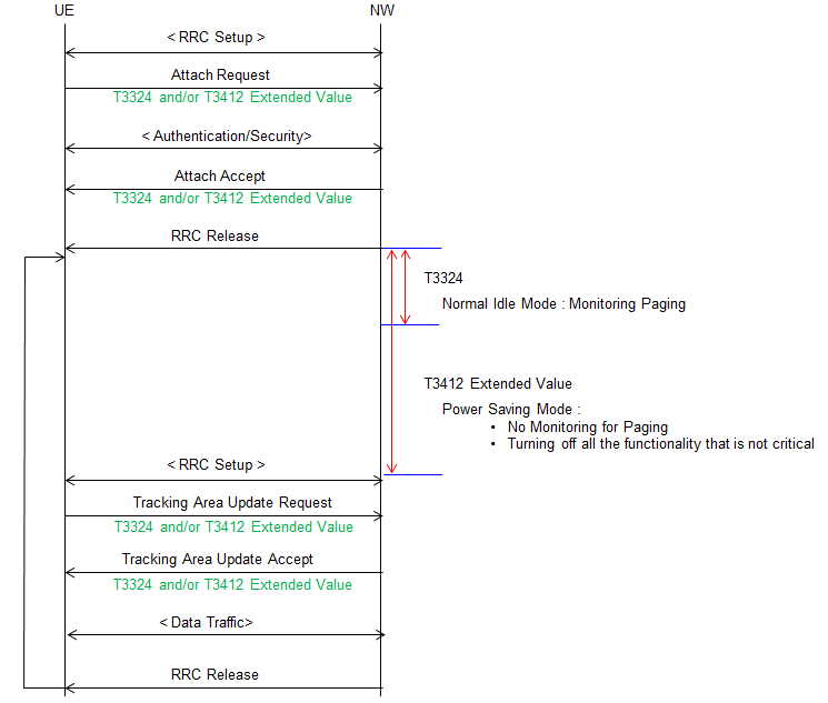
Figure 1. PSM timer sequence. Both timers start at RRC Release, T3324 ends the reachable period, and the UE stays in PSM until T3412 Extended Value expires and a Tracking Area Update brings it back.
- Attach Request carries the values the UE asks for, and Attach Accept carries the values the network allocates. The two sets can differ.
- After RRC Release, T3324 runs first. During T3324 the UE is in normal idle mode and monitors paging, so the network can still reach it.
- When T3324 expires, the UE enters Power Saving Mode. It does not monitor paging, and it turns off all the functionality that is not critical.
- T3412 Extended Value keeps running through PSM. When it expires, the UE sets up RRC again and sends Tracking Area Update Request.
- The Tracking Area Update Request and Accept carry the timer values again. So the UE and the network renegotiate PSM at every TAU.
- Data traffic can follow the TAU. After the next RRC Release the loop on the left starts again with both timers.
Now let's add what 24.301 says at the edges of this loop. The network accepts PSM only by including T3324 in ATTACH ACCEPT or TRACKING AREA UPDATE ACCEPT, with a value other than deactivated. The MME then runs its own active timer with the same value, and it restarts that timer each time it releases the NAS signalling connection. When the active timer expires, the MME typically stops paging the UE.
On the UE side, T3324 expiry lets the UE deactivate the AS layer and enter EMM-REGISTERED.NO-CELL-AVAILABLE. A T3324 value of zero lets the UE do this at once. The UE then stops most NAS timers, but T3412 and a short list of other timers keep running. The UE may also leave PSM at any time for mobile originated data or signalling, so PSM does not delay uplink traffic.
T3324 is the reachable window : it starts when the UE goes idle, and the UE monitors paging only while it runs.T3412 sets the PSM duration : the UE stays unreachable until the periodic TAU brings it back.The network grants PSM by sending T3324 : without a T3324 value other than deactivated, the UE cannot use PSM.The MME mirrors T3324 with its active timer : so both sides know when paging stops making sense.Uplink traffic never waits : the UE may leave PSM at any time for mobile originated data.
Where are the two timers carried in the NAS messages ?
Figure 1 shows which messages carry the timers, but not how the values are encoded. The encoding matters, because the same five bit number means seconds in one unit and hundreds of hours in another. So always read the unit before the value.
Followings are set of examples of NAS messages which configures the two timers. In terms of the timer parameters, all the messages have the same structure
< Attach Request/Attach Accept/Tracking Area Update Request/Tracking Area Update Accept > - decoded NAS message,
Attach request ::= DIVISION
...
  +-T3324 value ::= TLV OPTIONAL:Exist
  | +-Octet1 ::= DIVISION
  | | +-GPRS Timer 2 IEI ::= IEI [6A]
  | +-Octet2 ::= DIVISION
  | | +-Length of GPRS Timer 2 contents ::= LEN (0..255) [1]
  | +-Octet3 ::= DIVISION
  |   +-Unit ::= CHOICE [value is incremented in multiples of 2 seconds]
                 // Unit field has following options
                 //    value is incremented in multiples of 2 seconds
                 //    value is incremented in multiples of 1 minute
                 //    value is incremented in multiples of decihours
                 //    value indicates that the timer is deactivated
  |   +-GPRS timer2 value ::= INT (0..31) [10]
  +-T3412 extended value ::= TLV OPTIONAL:Exist
    +-Octet1 ::= DIVISION
    | +-GPRS Timer 3 IEI ::= IEI [5E]
    +-Octet2 ::= DIVISION
    | +-Length of GPRS Timer 3 contents ::= LEN (0..255) [1]
    +-Octet3 ::= DIVISION
      +-Unit ::= CHOICE [value is incremented in multiples of 1 hour]
                 // Unit field has following options
                 //   value is incremented in multiples of 10 minutes
                 //   value is incremented in multiples of 1 hour
                 //   value is incremented in multiples of 10 hours
                 //   value is incremented in multiples of 2 seconds
                 //   value is incremented in multiples of 30 seconds
                 //   value is incremented in multiples of 1 minute
                 //   value is incremented in multiples of 320 hours // Rel14 or later(24.008)
                 //   value indicates that the timer is deactivated.
      +-Timer value ::= INT (0..31) [12]
The capture is an Attach Request with both IEs present. T3324 value uses IEI 6A and the GPRS timer 2 format of 24.008. Its unit is 2 seconds and its timer value is 10, so the UE asks for a T3324 of 20 seconds. T3412 extended value uses IEI 5E and the GPRS timer 3 format. Its unit is 1 hour and its timer value is 12, so the UE asks for a periodic TAU timer of 12 hours. Both IEIs match 24.301 v20.0.0, in the Attach Request and in the other three messages.
The comments in the capture list the units from 24.008, and two of them deserve a closer look. The first is the 320 hours unit of GPRS timer 3. The UE interprets it as 320 hours only in an integrity protected message, and otherwise as 1 hour. The second is the deactivated unit. It does not apply to the T3412 extended value IE, and a UE that receives it treats the IE as not included in the message.
24.301 also puts conditions on which side may include each IE. The UE includes T3324 value in ATTACH REQUEST when it requests PSM. It may add T3412 extended value only together with T3324 value and when it indicates support for the extended periodic timer. The MME includes T3324 value in ATTACH ACCEPT only if the UE asked for it and the MME accepts PSM. When ATTACH ACCEPT carries T3412 extended value, the UE uses it for T3412 instead of the T3412 value IE.
Read the unit first : a timer value of 12 means 24 seconds in one unit and 3840 hours in another.T3324 uses GPRS timer 2 : IEI 6A, with units of 2 seconds, 1 minute and decihours.T3412 extended value uses GPRS timer 3 : IEI 5E, with units from 2 seconds up to 320 hours.The 320 hours unit needs integrity protection : without it the UE reads the unit as 1 hour.The accept message wins : the UE runs the values from ATTACH ACCEPT or TRACKING AREA UPDATE ACCEPT, not the values it requested.
What value to set for these timers ?
As you see, the rage of the timer values you can set for these timers are pretty wide. Especially the range for 'extended value' would rage from a couple of minuites to over 400 days.
Basically it is completely up to Network Operators to specify the timer. However, to make various devices globally and seamlessly and globaly it would be good to have some guidelines for the settings. Recently (Oct 2017), GSMA put forward some kind of guideline for this in 6.1 PSM Standalone Timers in LTE-M Deployment Guide.
Let's work out the actual ranges from the units. T3324 uses GPRS timer 2, whose largest unit is the decihour, or 6 minutes. So T3324 reaches at most 31 x 6 minutes, which is 186 minutes. T3412 extended value reaches 31 x 320 hours, which is 9920 hours or about 413 days. That is the source of the figure of over 400 days above. Strictly, the smallest non-zero value of both timers is 2 seconds.
Each timer trades energy against reachability. A longer T3324 keeps the UE reachable for longer after each contact, but the UE spends that time in idle mode and monitors paging. A longer T3412 means fewer wake-ups, but mobile terminated data can wait up to one full T3412 period. So the right values depend on how often the application needs to reach the device, not only on the battery.
The network side has to follow the chosen values too. The MME typically runs a mobile reachable timer with a value similar to the periodic TAU timer. When that timer expires, the MME clears the PPF flag and starts an implicit detach timer, instead of deleting the bearers at once. With a T3412 of hours or days, these MME timers have to be long enough, or the MME detaches a UE that is only sleeping. For downlink data that arrives during PSM, the MME can ask the S-GW for extended buffering, depending on operator configuration.
T3324 is short and T3412 is long : T3324 reaches 186 minutes at most, and T3412 extended value reaches about 413 days.The two timers pull in opposite directions : a longer reachable window costs energy, and a longer PSM period costs mobile terminated latency.MME timers must match T3412 : the mobile reachable timer and the implicit detach timer have to cover the PSM period.Downlink data can be buffered : the MME can request extended buffering in the S-GW while the UE is in PSM.
Reference
[1] Live demo: Improving IoT Device Battery Life with Network Power Saving Mode for LTE and GSM Devices (YouTube)
[2] 24.301-8.2.1.12 T3412 extended value
[3] C1-113207 : Regarding T3412 Extended Value
[4] LTE Cat-0’s Power Saving Mode: What it Could Mean for Cellular IoT
[5] GSMA LTE-M Deployment Guide
[6] 3GPP TS 23.401 v20.0.0 - 4.3.5.2 Reachability Management for UE in ECM-IDLE state, 4.3.22 UE Power Saving Mode
[7] 3GPP TS 24.301 v20.0.0 - 5.3.11 Power saving mode, 5.5.1 Attach procedure, 8.2.4 Attach request
[8] 3GPP TS 24.008 v20.0.0 - 10.5.7.4 GPRS Timer 2, 10.5.7.4a GPRS Timer 3