|
4G/LTE - Network Architecture |
||
|
LTE Network Architecuture and Interface
Most of my carrier about wireless area was about the wireless communication between UE (Mobile phone) and eNB/BTS, I tend to assume that all other readers has the same interest/focus as mine. I know this is not the case and there are wide varieties of readers who is working in a little different area with different focus. But so often I found myself forgetting this fact. Pretty often when I am talking to other people, I often mis-interpret what I am told and found that it is mainly because of different focus. The most frequent difference that I noticed were the different point of observation in overall network architecture and different level of the details. So I decided to write a post which can be visuallize the details of overal LTE networks with various different angle so that we can explicitely point of the points on which both parties focus. Even when you are not directly talking to me, it would be good for you to keep these snapshots in your mind and associate these visualization to whatever you are reading/studying about LTE protocol.
I will keep adding the snapshots/illustrations as I found it usefual.
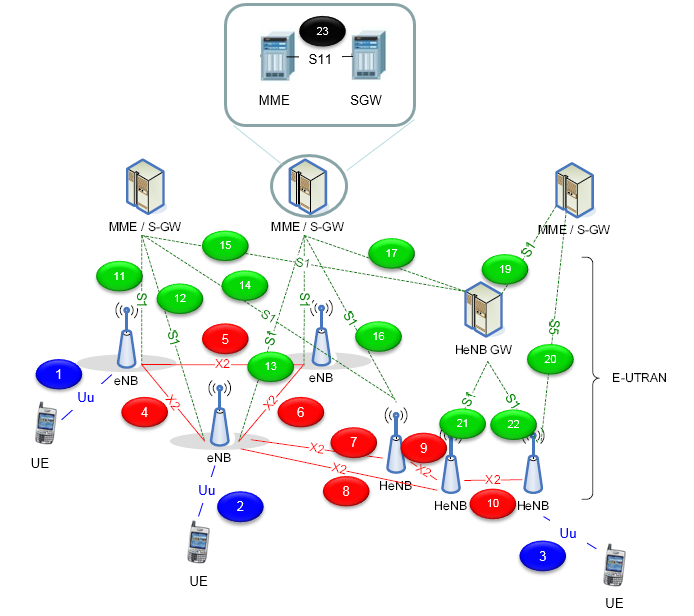
< Figure 1 : Network Architecture with the focus on connecting interface >
Main structure of this illustration is based on 3GPP 36.300, but I added a couple of new components and labeled each connection as a number. You may use this number (label) when you are communicating with others... like 'I am talking about the protocol sequence flowing through (1)' or 'I want to talk about the signaling message flow along UE <--> (1) <--> (11) <--> MME/S-GW'.
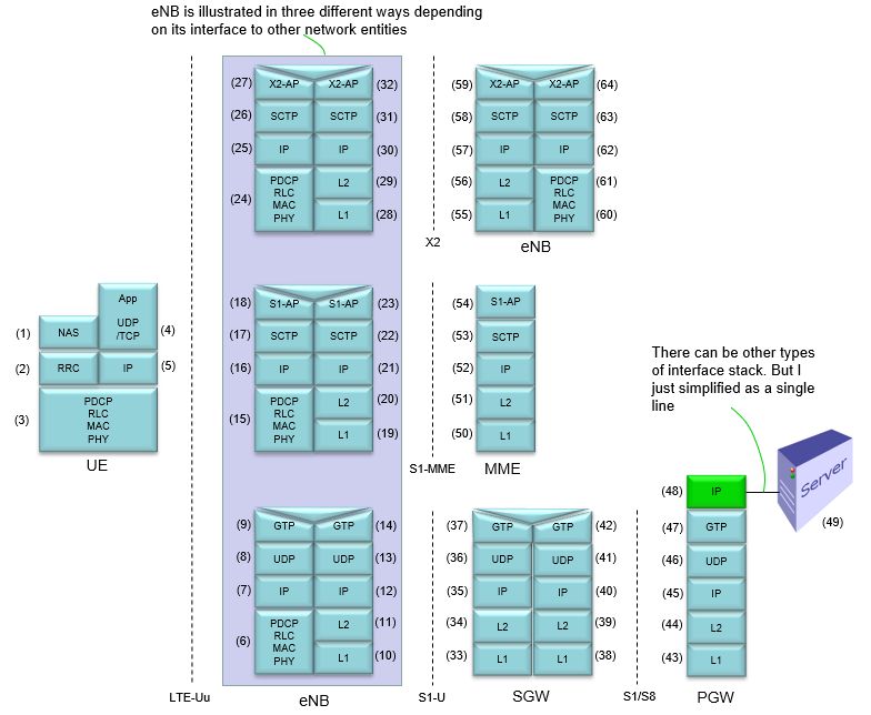
< Figure 2 : Network Architecture with the focus on Protocol Stack >
Main structure of this illustration is based on 3GPP 36.300, but I combined the multiple figures from the document into single picture to let you follow from the UE to the other end point within single figure. You may use this number (label) when you are communicating with others... like 'I want to talk about the data flow along (4) <--> (5) <--> (3) <--> (6) <--> (7) <--> (8) <--> (9) <--> (14) <--> (13) <--> (12) <--> (11) <--> (10) <--> (37) <--> (36) <--> (35) <--> (34) <--> (33) <--> (42) <--> (41) <--> (40) <--> (39) <--> (38) <--> (43) <--> (44) <--> (45) <--> (46) <--> (47)<--> (48) <--> (49)'. I know the order of numbers seems confusing.. but it would be helpful to be 'stay awake' if you follow through these numbers one by one :)
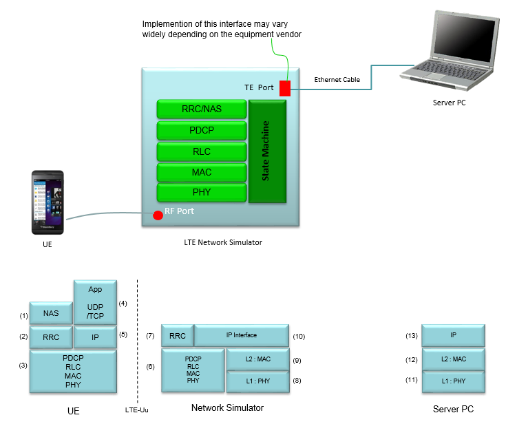
< Figure 3 : Example of Network Architecture with Test Equipment >
Pretty often I am getting questions from people like 'Can you do this or that with the test equipment ?'. In most case they are doable, but in some case test equipment can only mimic the behavior but not exactly as in real network. In many cases, these difference between test equipment and real network does not matter (especially for testing about radio protocol over Uu interface meaning 'between UE and eNB', but there are some cases that these difference make huge difference in terms of test result. So it would be good if you can get the detailed information from your equipment vendor and draw this kind of diagram for the specific test equipment you are currently using. This is just one example. This may not be same as the equipment that you are currently using.
|
||