Uplink waveform in LTE-NB is same as in legacy LTE Uplink. That is, LTE-NB Uplink is also using SC-FDMA. But there is some differences between LTE-NB and legacy LTE in terms of structure of uplink signal. I mean there is slight differences in terms of Uplink resource grid (frame structure). In addition, there is a new unit called RU(Resource Unit) that exisits in LTE-NB but not used in legacy LTE.
- Tables defining Uplink Frame Structure
- NPUSCH Format
- Frame Structure/Resource Grid
- RU (Resource Unit)
Tables defining Uplink Frame Structure
Uplink Frame Structure of LTE-NB can be summarized in the following three tables. If you can interpret these tables into a correct graphical format, you already understand all the details of Uplink frame structure. Most of technical materials (or white papers) write several pages in words based on these small tables.
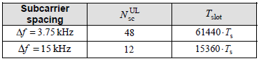
< 36.211-10.1.2.1 >
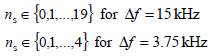
< 36.211-Table 10.1.2.1-1: NB-IoT parameters >
NPUSCH Format
There are two types of NPUSCH format, and the UE does not explicitly select them through a dedicated field in the DCI. Instead, the format is implied by the purpose of the transmission that the scheduling decision triggers. When the UE receives an uplink grant via DCI Format N0, it is expected to transmit UL-SCH user data, so NPUSCH Format 1 is used. When the UE receives a downlink assignment via DCI Format N1 and successfully decodes the associated NPDSCH, it must return HARQ-ACK/NACK feedback, so the UE transmits this acknowledgement using NPUSCH Format 2, which follows a fixed-size, single-tone structure.
The NPUSCH Format (Format 1 vs. Format 2) is determined strictly by the purpose of the transmission (what payload you need to send).
It is not explicitly "selected" by a field inside the DCI; rather, it is implied by which DCI triggered the transmission.
NPUSCH Format 1 (Uplink Data)
- Purpose: Used to transmit actual User Data (UL-SCH).
-
How it is determined:
- The UE receives DCI Format N0 (Uplink Grant).
- Since DCI N0 grants permission to send data, the UE automatically uses Format 1.
-
Characteristics from your table:
- Variable size (slots/symbols vary based on subcarrier spacing).
- Supports both Single-Tone and Multi-Tone (depending on configuration).
NPUSCH Format 2 (Uplink Control / ACK)
- Purpose: Used to transmit HARQ-ACK/NACK feedback for downlink data.
-
How it is determined:
- The UE receives DCI Format N1 (Downlink Assignment) and successfully decodes the associated Downlink Data (NPDSCH).
- The UE must send an acknowledgement back. This specific feedback transmission is automatically done using Format 2.
-
Characteristics from your table:
- Fixed Size: Always takes 4 Slots.
- Single Tone: Always uses Single-Tone transmission (3.75 kHz or 15 kHz).
Summary Table
|
NPUSCH Format |
Payload |
Triggered By |
Subcarriers |
|---|---|---|---|
|
Format 1 |
User Data |
DCI Format N0 (Uplink Grant) |
1, 3, 6, or 12 |
|
Format 2 |
HARQ-ACK |
DCI Format N1 (Downlink Schedule) |
1 (Fixed) |
Frame Structure/Resource Grid
The first thing you might have noticed from the tables above would be that there are two different types of sub-carrier spacing in LTE-NB. One is 15 Khz (this is same as in legacy LTE) and the other one is 3.75 Khz.
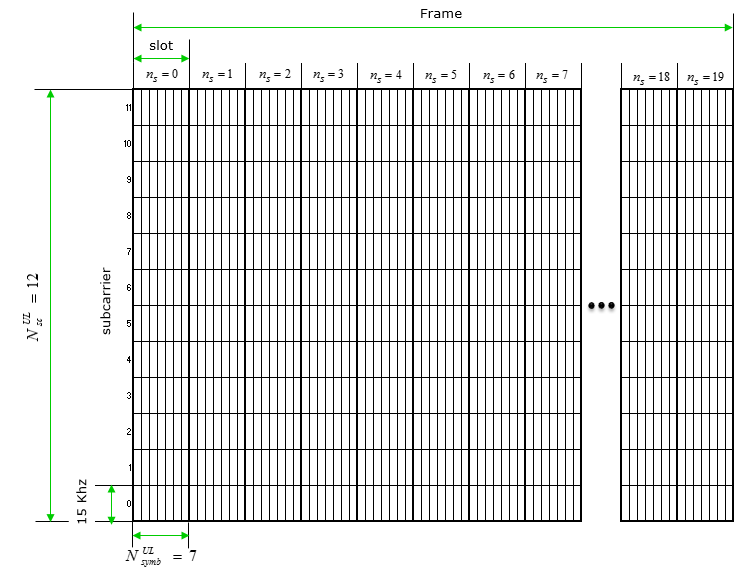
Let's draw a resource grid in a frame based on 15 Khz subcarrier spacing. In this case, you can easily calculate that you can put 12 sub carriers within 180 Khz BW(LTE-NB System Bandwidth). And in 36.211-10.1.2.1, you see there are 20 slots within a radio frame. If you translate these into a graphical format, it would become as follows. Basically this is same as in legacy LTE uplink resource grid.
Now let's draw a resource grid in a frame based on 3.75 Khz subcarrier spacing. In this case, you can easily figure out that you can put 48 sub carriers within 180 Khz BW(LTE-NB System Bandwidth). And in 36.211-10.1.2.1, you see there are 5 slots within a radio frame. If you translate these into a graphical format, it would become as follows.
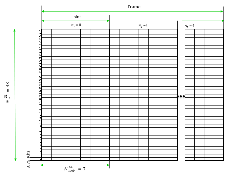
Comparing 3.75 Khz resource grid and 15 Khz resource grid, you would notice followings
- Sub-carrier spacing in 3.75 Khz became narrower by 4 times comparing to 15 Khz resource grid (this is simple math)
- Symbol length in 3.75 Khz resource grid becaome longer by 4 times compapring to 15 Khz resource grid (this is a basic properties of OFDM. The narrower sub-carrier spacing is, the longer symbol length is).
- Length of a Radio Frame is defined to be same (10 ms) in both 3.75 Khz resource grid and 15 Khz resource grid
- The number of slots within a radio frame in 3.75 Khz resource grid became smaller by 4 times compapring to 15 Khz resource grid (36.211-10.1.2.1)
- The number of OFDM symbols within a slot is same (7) in both 3.75 Khz resource grid and 15 Khz Grid
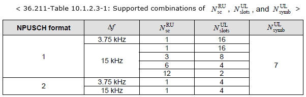
RU (Resource Unit)
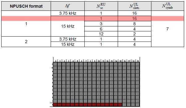
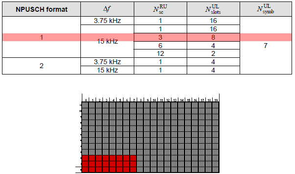
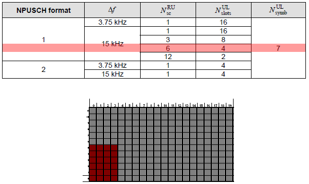
A kind of new concept in LTE-NB UL resource assignment comparing to legacy LTE, LTE-NB introduce a new resource unit called RU(Resource Unit) as a basic unit for PUSCH allocation. This unit can take several different types of configurations as defined in the table shown below.
Now let's try to translate each item of this table into a graphical form (resource grid).
Let's take the item highlighed in red show below. It is for NPUSCH format 1, Sub Carrier Spacing = 15 Khz, the number of sub carrier in one RU is 1 and the number of slots within the RU is 16. The graphical representation that I interpreted is as shown below the table.
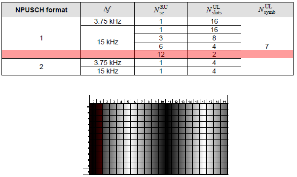
NOTE : The resource grid shown below is just an example of this RU. The starting subcarrier position can vary in real operation based on Subcarrier Index field in DCI (36.213 Table 16.5.1.1-1).
Let's take next item highlighed in red show below. It is for NPUSCH format 1, Sub Carrier Spacing = 15 Khz, the number of sub carrier in one RU is 3 and the number of slots within the RU is 8. The graphical representation that I interpreted is as shown below the table.
NOTE : The resource grid shown below is just an example of this RU. The starting subcarrier position can vary in real operation based on Subcarrier Index field in DCI (36.213 Table 16.5.1.1-1).
Let's take next item highlighed in red show below. It is for NPUSCH format 1, Sub Carrier Spacing = 15 Khz, the number of sub carrier in one RU is 6 and the number of slots within the RU is 4. The graphical representation that I interpreted is as shown below the table.
NOTE : The resource grid shown below is just an example of this RU. The starting subcarrier position can vary in real operation based on Subcarrier Index field in DCI (36.213 Table 16.5.1.1-1).
Let's take next item highlighed in red show below. It is for NPUSCH format 1, Sub Carrier Spacing = 15 Khz, the number of sub carrier in one RU is 12 and the number of slots within the RU is 2. The graphical representation that I interpreted is as shown below the table. This is same pattern of resource allocation in legacy LTE.
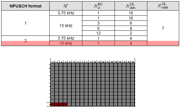
Let's take next item highlighed in red show below. It is for NPUSCH format 2, Sub Carrier Spacing = 15 Khz, the number of sub carrier in one RU is 1 and the number of slots within the RU is 4. The graphical representation that I interpreted is as shown below the table.
NOTE : The resource grid shown below is just an example of this RU. The starting subcarrier position can vary in real operation based on Subcarrier Index field in DCI (36.213 Table 16.5.1.1-1).
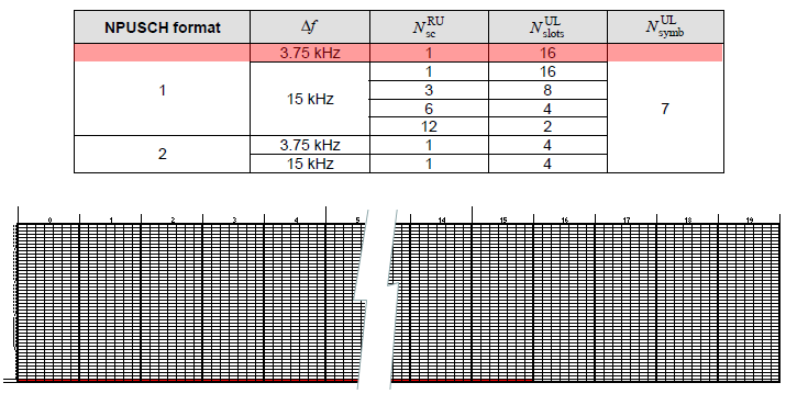
Let's take next item highlighed in red show below. It is for NPUSCH format 1, Sub Carrier Spacing = 3.75 Khz, the number of sub carrier in one RU is 1 and the number of slots within the RU is 16. The graphical representation that I interpreted is as shown below the table. This is same pattern of resource allocation in legacy LTE.
NOTE : The resource grid shown below is just an example of this RU. The starting subcarrier position can vary in real operation based on Subcarrier Index field in DCI (36.213 Table 16.5.1.1-1).
Let's take next item highlighed in red show below. It is for NPUSCH format 1, Sub Carrier Spacing = 3.75 Khz, the number of sub carrier in one RU is 1 and the number of slots within the RU is 4. The graphical representation that I interpreted is as shown below the table.
NOTE : The resource grid shown below is just an example of this RU. The starting subcarrier position can vary in real operation based on Subcarrier Index field in DCI (36.213 Table 16.5.1.1-1).
