I want to talk a little bit about Interference between multi cells (Inter Cell Interference). In this page, I will show you some of the measurement result but don't pay too much attention to the exact measurement values. You would get different value in different situations or the value shown here would be different from the value measured by UE in live network. But general trend and characteristics of the interence would apply to most of the cases. You should be well aware of this kind of properties especially if you are working on test cases related to various mobility issues (Cell Selection, Reselection, Measurement Report, Handover, Redirection etc).
Followings are the general characteristics (tendencies) in intercell interference.
- Interfence among Cells with the same frequency (Intrafrequency Interference) is much higher (more serious) than the interference among cells with different frequency. (Compare the result between Interfrequency and Intrafrequency measurement result shown below).
- Within Intra frequency cells, the interference between cells with same reference signal location tend to be higher than the interference between cells with different reference signal locations.
- When the Interference come into play ?
- Inter Frequency Interference between LTE and LTE with Varying Channel Power
- Intra Frequency Interference between LTE and LTE with Varying Channel Power
- Intra Frequency Interference between LTE and LTE with Varying Physical Cell ID
- Why the reference signal position decides it
- Reference
When the Interference come into play ?
Interference is easy to picture once a connection is running, and easy to forget before one exists. The awkward case is the one below. A UE that has just powered on holds no timing, no cell identity and no channel estimate. It has to find a cell using signals it cannot yet equalise.
Now the question is When we have to take this interference seriously ?.
The general answer is 'Always'. We have to take precautions anytime and as much as possible. I think The most crucial situation is at cell detection/selection/reselection stage because it would be the worst case if you power on the mobile phone and it fail to detect any cell due to the interference. To understand on possibile mode of interference, you need to know the detailed procedure/factors for this process. Following is what's happenning when you power on UE.
i) Frequency Aquisition
ii) Primary Sync Signal Aquisition (Slot Timing Aquired, Secondary Sync Signal Scrambling Code Aquired)
iii) Secondary Sync Signal Aquisition (Frame timing Aquired, Cell Group ID sequence aquired)
iv) with PSS and SSS, Cell ID can be calculated
v) with Cell ID, Reference Signal Location is detected
vi) With the help of Reference Signal, PBCH (MIB) can be detected
vii) From MIB, SFN and System BW can be detected
viii) Decode PCFICH and detect how many symbols are allocated for PDCCH.
ix) Decode DCI for SIB1 from PDCCH
x) Decode SIB1 and get the scheduling information for other SIBs
xi) Decode SIBs (other than SIB1)
Now let's think of each of the steps and what might be the issues with those steps in terms of interference.
- Most of the frequency Aquisition is based on RSSI Scan for each subcarriers within all the bands that the UE is configured to support. Because of this mechanism, UE may have difficulties to find correct frequency if the frequency of two or more cells are in very close neighbouring location or the frequencies are partially overlapping.
Acquisition is the worst moment for it : the UE has no channel estimate yet, so it cannot cancel what it has not measured.Each step depends on the one before it : a lost sync signal costs the cell identity, the reference signal position and everything after them.Intra frequency is the condition every step names : the same phrase appears against the sync signals, the reference signals, PCFICH, PDCCH and the SIBs.The identity does more than name the cell : it places the reference signals, it places PCFICH, and it seeds the scrambling.- There wouldn't be much problem if the frequency of cells are different (Interfrequency), but UE may suffer from inteference if the frequency of the neighbouring cells are same.
- This inteference would be more serious if the reception of Sync signal from multiple cells are better aligned in time domain. (Even though they tried to design the sync signal interfering as little as possible, but still the sync signal is not 100% orthogonal).
- This inferference would be especially serious among intra frequency cells.
- The location of Reference Signal is primarily determined by Physical Cell ID and the Scrambling Code is also influenced by Physical Cell ID(PCI). So if the Physical Cell ID are different, there should be no interference for this reference signal. But in reality there would be a certain degree of interference whatever PCIs you allocate for the neighbouring cells.
- Location of Reference signal gets same in some case even though PCI is different. (Refer to Downlink Reference Signal page if you are interested in details on this). So you need to very carefully assign PCI to each of the cells in such a way to minimize the interference.
- This interference would be especially serious among intra frequency cells.
- Location of PCFICH is mainly determined by System Bandwidth and Physical Cell ID (PCI). In most intra frequency settings, the neighbouring cells are using the same system bandwidth. So even though PCI is different, it is highly likely that there are certain level of overlapping of PCFICH location between cells.
- Since PCFICH is located only at the first symbol of each subframe, this PCFICH interference would get less serious if the timing sync of the signal coming from neighbouring cell is not well synchronized.
- This interference would be especially serious among intra frequency cells.
- If the location of DCI in PDCCH region is same or overlapping among multiple cells, UE would have more difficulties of decoding the DCI and as a result may fail to decode SIB1.
- If the multiple cells are transmitting SIB1 in the same RB (Resource Blocks), the possibility of interferences would get higher.
- This interference would be especially serious among intra frequency cells.
- If the SIB transmission scheduling is same between neighbouring cells, the interference would get higher
- If the multiple cells are transmitting SIBs in the same RB (Resource Blocks), the possibility of interferences would get higher
i) Frequency Aquisition
ii) Primary Sync Signal Aquisition (Slot Timing Aquired, Secondary Sync Signal Scrambling Code Aquired)
iii) Secondary Sync Signal Aquisition (Frame timing Aquired, Cell Group ID sequence aquired)
iv) with PSS and SSS, Cell ID can be calculated
v) with Cell ID, Reference Signal Location is detected
vi) With the help of Reference Signal, PBCH (MIB) can be detected
vii) From MIB, SFN and System BW can be detected
viii) Decode PCFICH and detect how many symbols are allocated for PDCCH.
ix) Decode DCI for SIB1 from PDCCH
x) Decode SIB1 and get the scheduling information for other SIBs
xi) Decode SIBs (other than SIB1)
Inter Frequency Interference between LTE and LTE with Varying Channel Power
In this example, I setup two cells with different band (Inter frequency, Inter band) as follows. I used BTS1 as a serving cell and BTS2 as a neighbouring interfering cell. and I used a Vector signal analyzer as a kind of DUT and measured EVM (Error Vector Magnitude) detected by the serving cell.
- BTS 1 = Band 4
- BTS 2 = Band 17
- Test Variable : Cell of BTS2 changes
- Measurement : BTS1
As you see in the result shown below, there is almost no difference in the measured EVM at BTS1 regardless of the power of interfering cell. (In this example, the frequency of two cell is very far away from each other, so interference from the other cell is negligible, if the fequency of neighbouring cell is closer to each other, you would see stronger interference than in this example).
The figure below holds six constellations. Each panel prints the serving cell on its first line, the interferer on the second and the resulting EVM on the third. BTS1 never changes across the six. Only the RSRP of BTS2 moves.
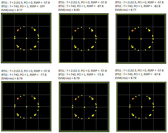
Figure 1. Inter frequency interference, with the interfering cell swept from off to 10 dB below the serving cell
BTS1 is identical in every panel : f = 2132.5, PCI = 0 and RSRP = -57.8 throughout.BTS2 climbs 20 dB across the sweep : off, then -87.8, -82.8, -77.8, -72.8 and -67.8, in steps of 5 dB.The EVM does not follow it : 8.77 with the interferer off, and 8.79 with it only 10 dB below the serving cell.The worst reading belongs to the quietest interferer : 8.93 at -87.8, which puts the whole spread inside the measurement noise.
The two frequencies are the reason. 2132.5 MHz sits in Band 4 and 740 MHz in Band 17, which leaves about 1.4 GHz between them. The receiver has filtered one away long before the other reaches the demodulator, so the interfering power has nothing left to act on.
Twenty decibels of interferer moves the EVM by 0.16 : 8.77 with it off, against 8.93 at its worst reading.The frequency separation is what protects it : Band 4 against Band 17 is about 1.4 GHz apart.The filter acts before the demodulator : the interferer never reaches the stage it could damage.This is the control case : the section below repeats it with one variable changed.
Intra Frequency Interference between LTE and LTE with Varying Channel Power
In this example, I setup two cells with same frequency (Intra frequency) as follows. I used BTS1 as a serving cell and BTS2 as a neighbouring interfering cell. and I used a Vector signal analyzer as a kind of DUT and measured EVM (Error Vector Magnitude) detected by the serving cell. I set the BTS1 power to be fixed and increased the power of BTS2 step by step and checked how the measurement EVM varies.
- BTS 1 = Band 4
- BTS 2 = Band 4
- Test Variable : Cell of BTS2 changes
- Measurement : BTS1
Just by looking at the constellation, you can intuitively notice that EVM gets larger (constellation gets worse) as the interferering cell power gets higher.
The EVM result shown here is a little extreme case. According to this result, the DUT (Vector signal Analyzer) fail to decode the signal if the cell power difference between two cell is less than 20. But in live network, the situation would be much better than this. Isolation between the two cell would be much better than this test environment and real UE (mobile phone) can decode signal much which is much worse than this since the chipset has channel estimation and use various error correction. However the point is that UE would experience pretty serious interference when it seems multiple cells with the same frequency around the UE.
You can see obvious difference (outstanding difference) if you compare this result with the previous case (Inter frequency case).
The figure below repeats that setup with one change. BTS2 now transmits on 2132.5 MHz, the same frequency as BTS1, and the power sweep runs through the same six steps.
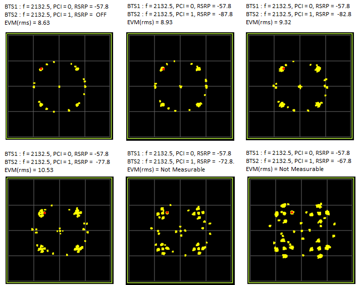
Figure 2. The same sweep on one frequency, where the two cells share every subcarrier
The panels run in the same order : interferer off, then -87.8 through -67.8 in steps of 5 dB.The EVM rises at every step : 8.63 with it off, then 8.93, 9.32, 10.53, and then no reading at all.Two panels return Not Measurable : -72.8 and -67.8, which are 15 dB and 10 dB below the serving cell.The constellation says the same thing : tight clusters become a ring, then a cloud, then a scatter with no structure left in it.
Set the two figures side by side and the contrast is arithmetic rather than impression. An interferer at -67.8 leaves the inter frequency EVM at 8.79. The same interferer at the same power leaves the intra frequency case with no reading. Only one thing differs, and it is whether the two cells share a frequency.
The 20 dB figure quoted above is readable from the panels themselves. At -77.8 the interferer is 20 dB down and the EVM is 10.53, which the analyser still reports. At -72.8 it is 15 dB down and the analyser gives no number. The threshold sits between those two panels.
One variable changed, and the result changed completely : the same sweep on one frequency ends with no reading.The break falls between 20 dB and 15 dB : 10.53 at 20 dB down, and nothing at 15 dB down.A 10 dB gap is no margin here : at -67.8 the inter frequency case was untouched.A signal analyser is stricter than a handset : the paragraph above says so, and a chipset recovers cases this instrument will not.
Intra Frequency Interference between LTE and LTE with Varying Physical Cell ID
In this example, I setup two cells with same frequency (Intra frequency) as follows. I used BTS1 as a serving cell and BTS2 as a neighbouring interfering cell. and I used a Vector signal analyzer as a kind of DUT and measured EVM (Error Vector Magnitude) detected by the serving cell.
- BTS 1 = Band 4
- BTS 2 = Band 4
- Test Variable : Cell of BTS2 changes
- Measurement : BTS1
I set the PCI of BTS1 to be fixed and changed PCI of BTS2 to various different values to how the measured EVM changes. This is to check how the location of reference signal of the serving cell and neigbhouring cell can influence on the interference (If you are not sure about how PCI is related to Reference Signal location, refer to Downlink Reference Signal page)
As shown in the following result, when there is almost no inteference between two cells when the cell power of the two different cell is very large.
Both figures below hold the frequency and the power fixed and move the identity of the interferer from 1 to 6. The serving cell stays at PCI 0 throughout. What separates the two figures is the size of the power gap.
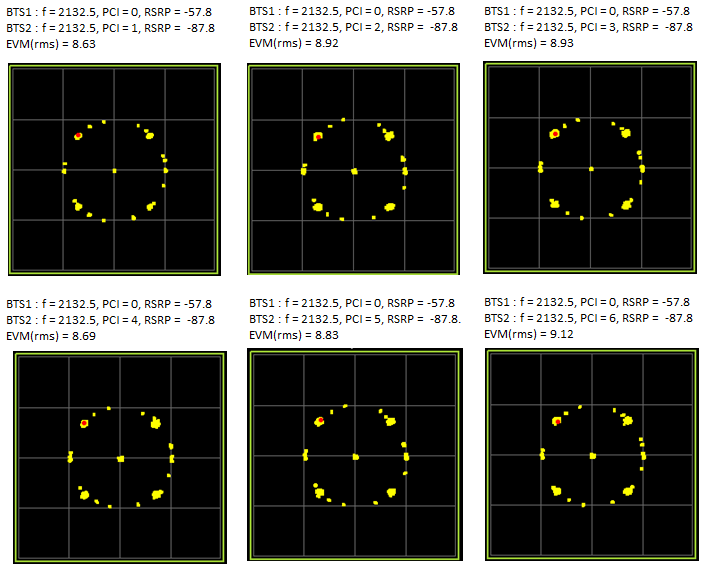
Figure 3. The identity sweep with the interferer 30 dB below the serving cell
The gap is 30 dB in every panel : -57.8 against -87.8, which the paragraph above calls very large.EVM stays inside a narrow band : 8.63, 8.92, 8.93, 8.69, 8.83 and 9.12, for PCI 1 through PCI 6.The highest reading is PCI 6 : 9.12, with PCI 3 next at 8.93.Half a unit of spread proves nothing on its own : which is what the figure below it is for.
Thirty decibels is a wide gap, and the page says as much. The figure below closes it to 20 dB, which is still generous against a live network, and at that point the identity stops being a detail.
But the cell power difference between two cells is relatively small (actually this difference in this example is still very big difference in live network), you would see the DUT (Signal Analyzer) fails to measure signal when the PCI is configured in such a way that the reference signal of the two cells are same.
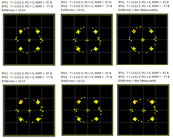
Figure 4. The same identity sweep with the gap closed to 20 dB
The gap is 20 dB in every panel : -57.8 against -77.8.Four identities give a reading : 10.54, 10.51, 10.27 and 10.22, for PCI 1, 2, 4 and 5.Two give none at all : PCI 3 and PCI 6 both return Not Measurable.The four that work sit within a third of a unit : 10.22 to 10.54, so what happens at 3 and at 6 is not a matter of degree.
Power alone does not explain the failures : every panel in the figure runs at the same 20 dB gap.The identity on its own does not explain them either : 1, 2, 4 and 5 all report, while 3 and 6 do not.The two that fail are three apart : and the section below works out why that is the number that matters.
Why the reference signal position decides it
PCI 3 and PCI 6 are the two that fail, and neither the power nor the frequency separates them from the other four. What separates them is where they put their reference signals. 36.211 fixes that position with one line of arithmetic.
Clause 6.10.1.2 maps the cell specific reference signals onto subcarriers k = 6m + (v + vshift) mod 6. It sets vshift to the physical cell identity modulo 6. A cell therefore uses one subcarrier in every six, and its identity chooses which one.
The same clause makes that shift a pair rather than a single value. Within a slot the variable v takes 0 in the first reference signal symbol and 3 in the second, for antenna port 0. Port 1 uses the reverse. Either way the cell lands on vshift and on vshift plus three.
The pair is what collides, and the pair repeats every three. Two cells share it when their identities agree modulo 3. Against a serving identity of 0, that picks out 3 and 6 from the six values tested and leaves 1, 2, 4 and 5 clear. The figure below draws the whole sweep over one resource block.
Figure 5. Reference signal positions for the seven lowest identities, computed from 36.211 clause 6.10.1.2
The shaded columns are the ones PCI 0 uses : subcarriers 0, 3, 6 and 9 of the twelve in a resource block.PCI 3 and PCI 6 fill exactly those columns : one because its shift is 0, the other because its shift is 3 and the pair wraps round.PCI 1, 2, 4 and 5 fall between them : their reference signals never touch a subcarrier PCI 0 is using.The rows repeat in threes : 1 and 4 share one comb, 2 and 5 share the other, and 0, 3 and 6 share the shaded one.The right hand column is the whole rule : PCI mod 3 decides it, and the measured results follow it exactly.
That modulo 3 is not an accident of the reference signal design. Clause 6.11 builds the identity as NIDcell = 3 NID1 + NID2, from a group number and a number between 0 and 2 inside it. The identity modulo 3 is that second number, and the second number is what the primary synchronisation signal carries.
Two cells whose reference signals collide are therefore the two cells that transmit the same PSS. Table 6.11.1.1-1 lists only three root sequences for it, 25, 29 and 34, so one identity in three shares it with any given cell. The acquisition list at the top of this page and this section name the same quantity.
One consequence reaches beyond this measurement. A reference signal collision costs more than an ordinary one, because the receiver builds its channel estimate from those symbols. A corrupted estimate is then applied to every symbol in the subframe, so the damage spreads well past the resource elements that were actually hit.
The reference signal comb is fixed by the identity : vshift is the identity modulo 6, and the pair repeats every three.Collision happens when two identities agree modulo 3 : which is 3 and 6 against a serving identity of 0.That is the same number the PSS carries : 36.211 splits the identity into a group of 168 and a value of 0, 1 or 2.One neighbour in three shares the comb : there are only three primary synchronisation sequences to go round.A corrupted estimate spreads the damage : the hit falls on the symbols the whole subframe is equalised with.
Reference
[1] 36.211 : 3GPP - E-UTRA; Physical channels and modulation, v19.3.0. Clause 6.10.1.2 gives the cell specific reference signal mapping and the cell specific frequency shift. Clause 6.11 gives the composition of the physical layer cell identity, and Table 6.11.1.1-1 the three root indices of the primary synchronisation signal.