Conceptually Dual Connectivity is very similar to Carrier Aggregation, but it is a little different from conventional carrier aggregation in fact that it happens between different sites (usually between a macro cell and small cell). Due to this, it is also called as inter-site carrier aggregation (Refer to 2.1 Small Cell enhancements of [1] and Carrier aggregation in Heterogeneous Networks of [2] ).
Two questions follow from that. The first is what the split looks like inside the two base stations. The second is what the two of them have to say to each other to set it up and take it down again. The rest of this page answers them in that order.
What does the architecture look like ?
Two base stations serving one UE need a rule for where each bearer lives. A bearer has a PDCP entity, an RLC entity and a MAC entity, and the drawing below is really a picture of where those three entities sit.
Following is overall architecture of Dual Connectivity based on 36.300 4.9 Support for Dual Connectivity ([3])
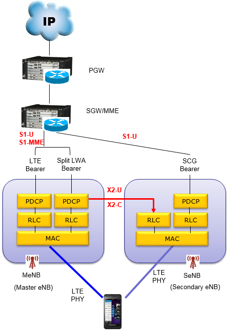
- The chain down the left is the core network. An IP cloud feeds the PGW, the PGW feeds the SGW/MME, and S1-U and S1-MME run from there to the MeNB.
- A second S1-U runs from the SGW/MME straight to the SeNB on the right, past the MeNB entirely.
- Three bearer stacks are drawn across the middle, labelled LTE Bearer, Split LWA Bearer and SCG Bearer.
- The left stack has PDCP, RLC and MAC in the MeNB and nothing in the SeNB. The right stack has PDCP, RLC and MAC in the SeNB and nothing in the MeNB.
- The middle stack is the split one. Its PDCP sits in the MeNB, and a red arrow carries its data across X2-U to an RLC entity in the SeNB. The two halves of one bearer therefore sit in two different base stations.
- Both base stations reach the phone at the bottom over their own LTE PHY, and the X2-C label marks the control plane link between them.
36.300 clause 4.9.2 names those three stacks, and the drawing uses different names for two of them. The specification calls them the MCG bearer, the split bearer and the SCG bearer.
The middle label needs care. LWA is LTE-WLAN Aggregation, which splits a bearer towards a WLAN termination rather than towards a secondary eNB, and it is a different feature. What the drawing actually shows is the dual connectivity split bearer, with PDCP in the MeNB and RLC in the SeNB over X2-U, which is exactly how 36.300 describes it.
The S1-U lines follow from the same clause. For an MCG bearer the S1-U connection terminates in the MeNB and the SeNB carries no user plane data at all. For a split bearer it also terminates in the MeNB, and PDCP data crosses to the SeNB over X2-U. For an SCG bearer the SeNB is connected to the S-GW directly over its own S1-U, and the MeNB carries none of that bearer's data.
One consequence is worth carrying into the next section. 36.300 notes that if only MCG and split bearers are configured, there is no S1-U termination in the SeNB at all. That is why some of the procedures below update the user plane path and others do not.
The bearer type is a question about PDCP : the MCG bearer keeps PDCP in the MeNB and the SCG bearer keeps it in the SeNB. The split bearer keeps PDCP in the MeNB and puts its RLC in the SeNB.X2-U carries data, not just signalling : the split bearer's PDCP data crosses it, so the interface between the two base stations is in the user plane path.Only the SCG bearer moves the S1-U endpoint : that is the case where the core network has to be told, and it is why a path update appears in some procedures below.
How do the procedures run ?
Six diagrams follow, and every one of them is a different answer to the same question: who decides, and what has to be told. The numbering runs straight through all six, so the step numbers are continuous even where the procedures are not.
Followings are the overall protocol sequence for various operations of Dual Connectivity. Even though I numbered all the steps in a single sequence, this sequence does not happen all the time. The sequence can be split into multiple blocks as labeled in the side bar on the right. (You may refer to 36.300 10.1.2.8 Dual Connectivity operation for further details).
The table below is the whole of that sequence in one view. It reads across the six blocks in order, and the columns are the four things that differ between them.
|
Block, as the side bar names it |
Steps |
Started by |
First message |
Data forwarding |
Last step drawn |
|
SeNB Addition |
1 - 12 |
MeNB |
SeNB Addition Request |
MeNB to SeNB |
Path Update Procedure |
|
MeNB Initiated SeNB Modification |
13 - 21 |
MeNB |
SeNB Modification Request |
MeNB to SeNB |
Path Update Procedure |
|
SeNB Initiated SeNB Modification |
22 - 31 |
SeNB |
SeNB Modification Required |
SeNB to MeNB |
Path Update Procedure |
|
Intra-MeNB handover procedure |
32 - 41 |
MeNB |
SeNB Modification Request |
drawn as one collapsed bar, with no direction shown |
Path Update Procedure |
|
MeNB Initiated SeNB Release |
42 - 48 |
MeNB |
SeNB Release Request |
SeNB to MeNB |
UE Context Release |
|
SeNB initiated SeNB Release |
49 - 56 |
SeNB |
SeNB Release Required |
SeNB to MeNB |
UE Context Release |
Two columns carry most of the information. Started by separates a Request from a Required, and Data forwarding says which way the bearer is moving. The rest of every block is the same three steps: an X2 exchange, an RRC reconfiguration of the UE, and a path update.
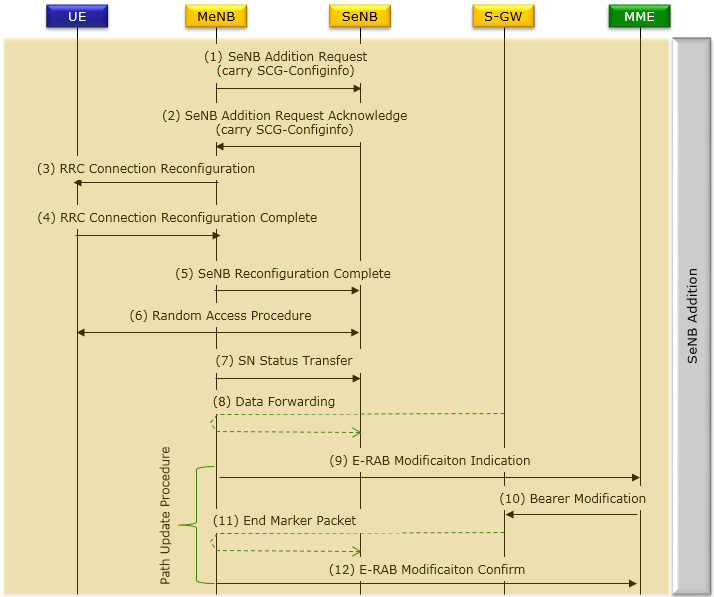
- The five lifelines are UE, MeNB, SeNB, S-GW and MME, and the band on the right names the block as SeNB Addition.
- Steps 1 and 2 are the X2 exchange. The MeNB sends a SeNB Addition Request carrying SCG-ConfigInfo, and the SeNB answers with a SeNB Addition Request Acknowledge carrying its own configuration.
- Steps 3 to 5 involve the UE. The MeNB reconfigures the UE over RRC, the UE answers, and the MeNB tells the SeNB that the reconfiguration succeeded.
- Step 6 is a Random Access Procedure between the UE and the SeNB, which is the UE synchronising to the secondary cell group for the first time.
- Steps 7 and 8 move any data the SeNB now owns. Steps 9 to 12 are bracketed on the left as the Path Update Procedure, and they run through the MME to the S-GW and back.
36.300 clause 10.1.2.8.1 fills in two things the diagram cannot show. This procedure adds at least the first cell of the SCG, which the specification calls the PSCell. Steps 9 to 12 apply to SCG bearers, because those are the bearers whose S1-U endpoint has moved.
The order of steps 4 and 6 is deliberately loose. 36.300 states that the order is not defined. The UE may send the reconfiguration complete before or after it performs random access towards the SCG, so a log that shows them the other way round is not wrong.
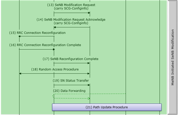
- The band names this one MeNB Initiated SeNB Modification, and steps 13 to 20 repeat the shape above with Modification in place of Addition.
- Step 21 is drawn as a single collapsed bar rather than as four messages. It is the same Path Update Procedure that steps 9 to 12 spelled out.
- 36.300 clause 10.1.2.8.2 gives the uses: adding or releasing SCG SCells, adding, modifying or releasing SCG bearers and the SCG part of split bearers, and triggering a PSCell change.
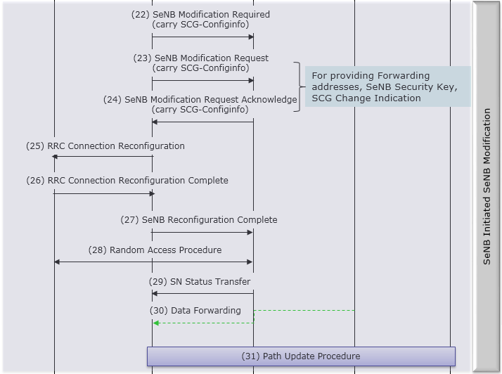
- The band names this one SeNB Initiated SeNB Modification, and the first message is the difference. Step 22 is a SeNB Modification Required, sent by the SeNB.
- Steps 23 and 24 are an ordinary MeNB initiated exchange nested inside it, and the note box beside them says why: for providing Forwarding addresses, SeNB Security Key, SCG Change Indication.
- Steps 29 and 30 point the other way from the diagrams above. The SN Status Transfer and the Data Forwarding arrows run from the SeNB towards the MeNB.
That reversal is not a drawing slip. 36.300 says its figure for this procedure depicts the case where a bearer context is transferred from the SeNB to the MeNB, so the data moves back the way it came.
One label differs from the current release. 36.300 v19.2.0 names the message at step 27 the SeNB Modification Confirm in the SeNB initiated flow, where the diagram reads SeNB Reconfiguration Complete, which is the name the MeNB initiated flow uses.
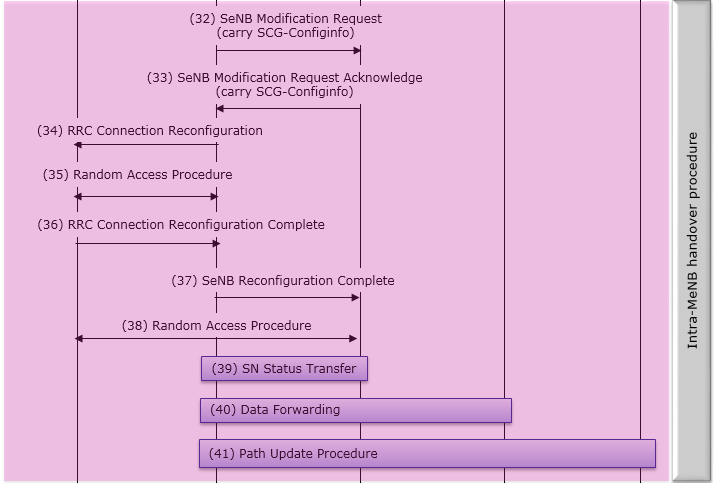
- The band names this one Intra-MeNB handover procedure, and it is the only diagram here with two Random Access Procedures in it.
- Step 35 is a random access towards the MeNB and step 38 is one towards the SeNB. The reconfiguration complete at step 36 falls between them, which is the ordinary handover shape rather than the addition shape.
- 36.300 clause 10.1.2.8.2.1 gives the purpose in one line: a handover within the same MeNB while the SCG stays in the same SeNB.
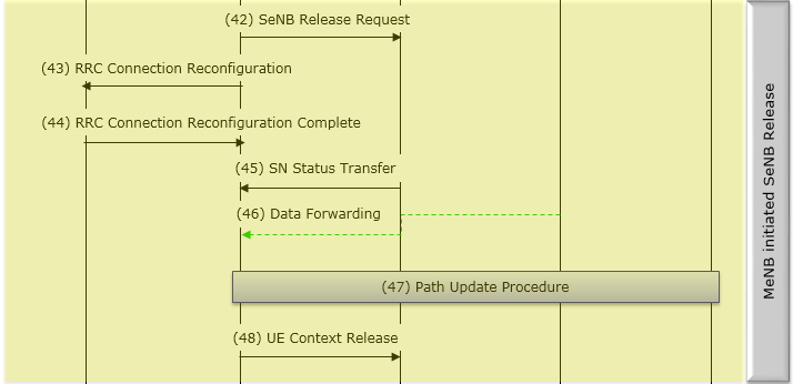
- The band names this one MeNB Initiated SeNB Release. Step 42 is a SeNB Release Request from the MeNB, and there is no acknowledgement drawn for it.
- Steps 45 and 46 run from the SeNB back towards the MeNB, because the bearer is moving back.
- Step 48 is a UE Context Release from the MeNB to the SeNB, and it comes after the path update rather than before it.
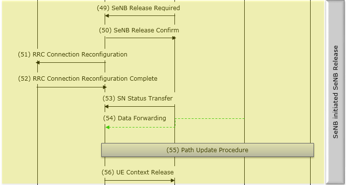
- The band names this one SeNB initiated SeNB Release, and the first two messages are the difference. Step 49 is a SeNB Release Required from the SeNB and step 50 is a SeNB Release Confirm from the MeNB.
- Everything from step 51 onwards matches the diagram above it, down to the UE Context Release at the end.
36.300 clause 10.1.2.8.3 adds one rule that neither release diagram shows. The recipient of a release request cannot reject it, whichever node sent it.
The six diagrams cover four of the nine procedures 36.300 lists under dual connectivity operation. Change of SeNB, MeNB to eNB change, SCG change, eNB to MeNB change, inter-MeNB handover without SeNB change and the addition of a hybrid HeNB as the SeNB are not drawn here.
Every procedure has the same three parts : an X2 exchange between the two base stations, an RRC reconfiguration of the UE, and a path update where the user plane endpoint moved.Who sends the first message is the whole difference : Request comes from the MeNB and Required comes from the SeNB, and the rest of each pair of diagrams is the same.The data forwarding arrow points where the bearer is going : towards the SeNB when a bearer moves out, and back towards the MeNB when one returns.A release cannot be refused : 36.300 states that the recipient of a SeNB Release Request cannot reject it.
Reference :
[1] LTE Release 12 and Beyond (Nokia Whitepaper)
[2] LTE-Advanced Carrier Aggregation Optimization (Nokia Whitepaper)
[3] ETSI TS 136 300 V13.3.0 (2016-04) - Radio Access Network (E-UTRAN); Overall description; Stage 2
[4] 36.300 : 3GPP - E-UTRA and E-UTRAN; Overall description; Stage 2, v19.2.0. Clause 4.9.2 defines the three bearer types and clause 10.1.2.8 defines the dual connectivity procedures. This is the current release of the document listed as [3] above, which the page cites in its 2016 ETSI form.