Walsh Code is a special set of code that is usually used for spreading digital data. One of the key characteristics of Walsh code is that all the members in the set is orthgonal to each other.
One of the best known application of Walsh code is data spreading for CDMA and the code used in CDMA has 64 elements and each of the code is based on following table. Each Walsh code is based on each row of the table.
- The table CDMA uses
- How is it generated ?
- < Visualization of the code >
- What the orthogonality buys and what it costs
The table CDMA uses
One warning belongs before the table rather than after it. The rows as printed are not orthogonal, and the paragraph below says so, which is the sort of thing a reader passes over and then cannot reproduce. Orthogonality appears only once the 0 and 1 have been mapped onto plus and minus one.
If you check the orthogonality between rows in this table, you would see these rows are not orthogonal to each other. But if you replace 0 with '1' and '1' with '-1' (i.e, 0->1, 1->-1) or if you replace 0 with -1 and 1 with 1 (i.e, 0->-1, 1->1), you will see the resulting rows become orthogonal to each other.
< 3GPP2 C.S0002-0_v1.0 Table 2.1.3.1.8.1-1. 64-ary Orthogonal Symbol Set >
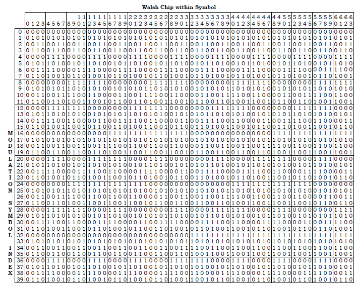
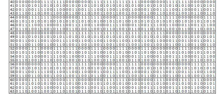
Figure 1. Rows 0 to 39 of 3GPP2 C.S0002-0_v1.0 Table 2.1.3.1.8.1-1. The column heading reads Walsh Chip within Symbol and runs 0 to 63, and the vertical label on the left reads Modulation Symbol Index.
Row 0 is entirely zeros : it maps to a code of all plus ones, which is the one row that carries no alternation at all.Row 1 alternates every chip and row 2 every two : the rate of alternation doubles as the row index passes each power of two. That is where the construction becomes visible.The column numbers are printed as two stacked digits : the tens above and the units below, so the header reads 0 through 63 across the width.The two axes are not the same thing : down the side is which code, across the top is which chip inside that code. Both run 0 to 63 and they mean different things.
How is it generated ?
Now let's see how this table is created. As is described in 3GPP2 C.S0002-0_v1.0 , these codes are created by an Hadamard matrix as shown below.

Figure 3. The rule the whole table comes from, in one line. Each step doubles the matrix by placing three copies of it and one complemented copy, and nothing else is needed.
The overbar on the fourth block is a complement, not a minus : the matrix is still in zeros and ones here. The opposite of 0 is therefore 1, not minus one.H4 is printed in full as a check : its four rows read 0000, 0101, 0011 and 0110. Those are the first four rows and columns of Figure 1.The recursion only reaches powers of two : 1, 2, 4 and so on to 64. That is why the code length and the number of codes are the same number.
With Matlab (or Octave), you can generate these table as shown below.
< Method 1 >
H1 = 0;
H2 = [H1 H1;H1 not(H1)];
H4 = [H2 H2;H2 not(H2)];
H8 = [H4 H4;H4 not(H4)];
H16 = [H8 H8;H8 not(H8)];
H32 = [H16 H16;H16 not(H16)];
H64 = [H32 H32;H32 not(H32)];
W64 = -1*(2 * H64-1);
H64 would give you the table shown above in the form of matrix. W64 gives you the version of the table that has following mapping.
-
0 is replaced with 1 (i.e, 0 -> 1)
-
1 is replaced with -1 (i.e, 1 -> -1)
Therefore, each row vector in W64 should be orthogonal to each other. You can easily check the orthogonality as follows.
W64(1,:) * W64(2, :)' will give you 0. It means row 1 and row 2 is orthogonal to each other.
W64(1,:) * W64(3, :)' will give you 0. It means row 1 and row 3 is orthogonal to each other.
You can try any two rows and all of them should give you 0.
< Method 2 >
If you generate the matrix as shown below, you can produce W64 table directly (in stead of generating H matrix first and then mapping 0 -> 1, 1 -> -1).
W1 = [1];
W2 = [W1 W1;W1 -W1];
W4 = kron(W2,W2);
W8 = kron(W2,W4);
W16 = kron(W2,W8);
W32 = kron(W2,W16);
W64 = kron(W2,W32);
You can do orthogonality check for this matrix as well in following way.
W64(1,:) * W64(2, :)' will give you 0. It means row 1 and row 2 is orthogonal to each other.
W64(1,:) * W64(3, :)' will give you 0. It means row 1 and row 3 is orthogonal to each other.
You can try any two rows and all of them should give you 0.
One thing the two methods leave unsaid is that they agree. Method 1 doubles the matrix with a complemented block and then maps 0 to plus one and 1 to minus one. Method 2 doubles it with a negated block directly. Complementing before the mapping and negating after it are the same operation. The two routes therefore produce the same 64 by 64 matrix, entry for entry.
The apostrophe in the check above matters as well. W64(1,:) and W64(2,:) are both row vectors of length 64. Multiplying one by the other without transposing the second is a dimension error rather than an answer. The transpose turns it into an inner product, which is the 0 the sentence promises.
Checking a single pair proves less than it looks. Every distinct pair of the 64 rows is orthogonal, which is 2016 pairs in total, and a row against itself gives 64 rather than 0. Both facts are worth knowing, because the second one is the signal a receiver is looking for.
Both methods give the same matrix : complementing zeros and ones before the mapping does exactly what negating plus and minus ones does after it.The orthogonality check needs a transpose : a row times a row is nonconformant, and a row times a transposed row is the inner product.All 2016 distinct pairs give zero : the property holds across the whole set rather than for the examples that happen to be listed.A row against itself gives 64 : the code length, and the number the wanted signal arrives with.
Visualization of the code
Reading orthogonality off a table of 64 numbers is hard, and watching it happen is not. The script below takes two of the codes, multiplies them chip by chip and accumulates the result, which is exactly what a receiver does.
code1 = 2;
code2 = 10;
subplot(4,1,1);
stairs(W64(code1,:));axis([0 65 -2 2]);title('code1');
subplot(4,1,2);
stairs(W64(code2,:));axis([0 65 -2 2]);title('code2');
subplot(4,1,3);
stairs(W64(code1,:) .* W64(code2,:));axis([0 65 -2 2]);title('code1*code2');
subplot(4,1,4);
stairs(cumsum(W64(code1,:) .* W64(code2,:)));axis([0 65 -10 10]);title('cumulative sum of code1*code2');
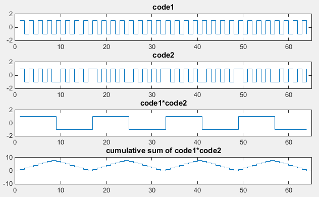
Figure 4. The bottom panel is the one that matters. The running sum reaches as far as 8 and arrives at exactly 0 after 64 chips, and that arrival is what orthogonality means in practice.
The top panel alternates every chip : code1 is row 2 of W64, so it changes sign on every chip. Only the constant row has a shorter period.The second panel changes more slowly and less regularly : code2 is row 10, and its pattern repeats over eight chips rather than two.The product is a clean square wave : eight chips up and eight down, so the third panel has a period of 16 even though neither input does.The running sum peaks at 8 and returns to 0 : it passes through zero at chips 16, 32 and 48 as well. The value that counts is the one at 64.A partial sum is not zero : stopping the receiver early, at chip 40 say, leaves a residue. The codes are orthogonal over a whole symbol and over nothing shorter.
What the orthogonality buys and what it costs
The table, the recursion and the plot all describe the code set without saying what it is for. The answer is that several transmitters can use the same frequency at the same time and still be separated, and the separation costs one multiplication and one sum per user.
Figure 5 works it through on eight chips, because 64 will not fit on a page and the arithmetic is identical. Two users pick different rows, multiply their bit by every chip of their own row, and transmit. The two transmissions add in the air, and the sum resembles neither of them.
Figure 5. The whole point of the code set, on eight chips instead of 64. Two transmissions add in the air and cannot be told apart by looking, and one multiplication and one sum separate them completely.
The air row is not either user : it holds 0, 0, +2, -2, 0, 0, +2 and -2, and a receiver looking at it without a code learns nothing.Multiplying by A turns every cancellation into an addition : the fourth row has no negative entries left, which is why the running total only climbs.The total is 8, the code length : the wanted bit arrives multiplied by the number of chips, which is where the processing gain of a spread system comes from.User B contributes exactly zero, not approximately : its eight terms cancel in pairs, so the interference from a perfectly aligned second user is absent.
The same arithmetic scales. With 64 chips and eight users transmitting at once, correlating against any one of the eight codes returns 64 times that user's bit and nothing from the other seven. That is code division, and it is the reason a CDMA cell can put many channels on one carrier.
The cost appears as soon as the codes stop lining up. Walsh codes are orthogonal at zero lag and at no other, and the failure is abrupt rather than gradual. Row 2 correlated against a copy of itself shifted by one chip gives -64 out of 64, a complete sign reversal. Rows 3 and 4 give 0 when aligned and -64 when one of them moves by a single chip.
Counting the cases makes the scale of it clear. Of the 4032 ordered pairs of distinct rows, 2730 stay at zero for every shift and the remaining 1302 do not. Roughly a third of the pairs lose the property entirely once alignment is lost.
That is why the code set works inside one transmitter and not between transmitters. A base station generates every downlink channel from one clock, so its own codes are aligned by construction. Two base stations cannot align with each other, so a second layer of coding has to do that job. The spread spectrum page sets the two layers side by side.
Code division is one multiply and one sum : the receiver needs the right row and the right starting chip, and nothing else.The wanted bit arrives multiplied by the code length : 64 for the CDMA set, which is the gain that covers the other users.Zero lag or nothing : for about a third of the pairs a one chip slip takes the correlation from 0 to 64. The property does not degrade gradually.64 codes is a firm ceiling : the set has exactly as many members as it has chips, so a cell can exhaust the code space.