In the domain of digital communications, establishing the timing sync is the first and the most important steps. It is the essential mechanism that ensures a harmonious exchange of data between a diverse array of devices and systems. From the interaction between mobile devices and cellular networks to the seamless connectivity within WLAN, and the simple yet profound pairing of Bluetooth device and even to wired communication like on-board communication,RS232,USB,LAN etc, each communication paradigm is underpinned by a sophisticated synchronization protocol. In this note, I want to overview on timing sync process of various types of communication. The main purpose of this note is provide readers with high level idea of the synchronization process. Covering the deep technical description of the sync process of not the scope of this note. If you can understand that timing synchroniztion is required in any kind of digital communication regardless of wireless or wired and if this note provide you with motivation to study further, the purpose of this note is fulfilled.
- Synchronization between CPU and Memory Communication
- Synchronization in RS232 Communication
- Synchronization in LAN Communication
- Synchronization in USB Communication
- Synchronization in Bluetooth Communication
- Synchronization in WiFi
- Synchronization in Cellular Communication
- What the seven cases have in common
The seven diagrams below are drawn to one template on purpose. Each shows two devices, a vertical line standing for each device's own sense of time, and a single arrow naming whatever carries timing between them. Reading them as a set before reading any section shows what changes as the link gets harder, and every section below refers back to its own figure by number.
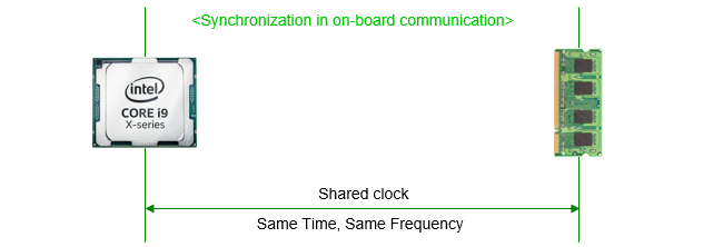
Figure 1. A CPU and a memory module, with the arrow reading shared clock, same time, same frequency. A single clock reaches both ends here, which is something no other link on this page can assume.
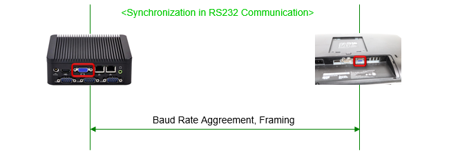
Figure 2. Two serial ports. The link carries no clock, so the arrow names an agreement made in advance instead. The framing bits mark where each character starts and stops.
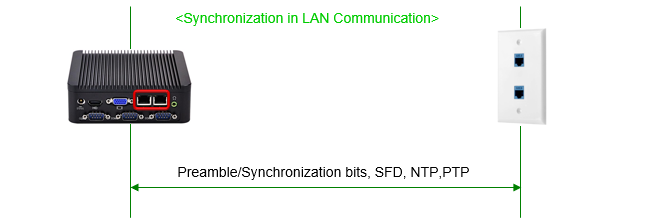
Figure 3. An Ethernet link. The arrow names both ends of the range at once : preamble and SFD bits for the individual frame, and NTP or PTP for the clock a whole network agrees on.
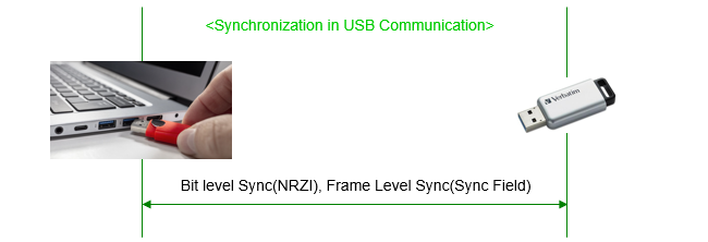
Figure 4. A USB link. The arrow separates the two levels the section below describes, bit level timing from the encoding and frame level timing from a field at the front of each packet.
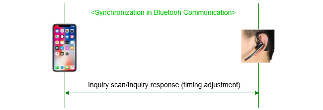
Figure 5. The page crosses from wired links to wireless ones here. The arrow names an exchange rather than a field, because neither device can be told the timing in advance and the two have to discover it between them.
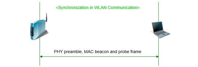
Figure 6. A WiFi link, whose arrow names two layers rather than one. The preamble is what the radio locks to, and the beacon or probe frame carries the timestamp the MAC layer uses afterwards.
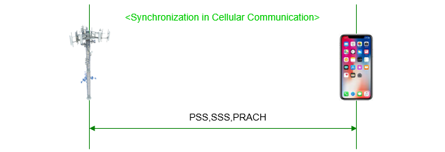
Figure 7. The hardest case. PSS and SSS travel downlink and PRACH travels uplink, so the arrow here covers timing in both directions.
Only Figure 1 has one clock in it : every other figure has two independent clocks to bring into agreement. The rest of the page is about how that is done.The geometry never changes and the arrow always does : two endpoints and one link in all seven, so the label on the arrow is the entire content of each picture.The wired figures name a field or a rate : a baud rate, a preamble, a sync field. All of them are things one side can put in the signal for the other to find.The wireless figures name an exchange : inquiry and response, beacon and probe, PSS and PRACH. Something has to go both ways before the two ends agree.Two of the titles carry typing slips : Figure 2 reads Aggreement and Figure 5 reads Bluetooh. Both are inside the pictures rather than in the page text.
Synchronization between CPU and Memory Communication
Time synchronization between a CPU and a memory chip, such as RAM, is focused on ensuring that data operations occur at precisely timed intervals, coordinated by a clock signal. In essence, time synchronization in CPU-memory communication revolves around the use of a shared clock signal, careful management of data transfer timings, adherence to latency requirements.
Clock Signal : The primary tool for time synchronization is the clock signal. Both the CPU and memory operate on this clock signal, which ensures that their operations are synchronized. This clock is a periodic pulse that dictates the timing of operations.Frequency Matching :The frequency of the clock signal is matched between the CPU and memory. This matching ensures that both components operate in sync, preventing timing-related errors.Data Transfer Timing : Data transfer between the CPU and memory is timed according to the clock cycles. The CPU and memory need to agree on when data is put on the bus (by the CPU) and when it is read (by the memory) or vice versa. This synchronization is crucial to prevent data corruption or loss.Latency Management : The memory has inherent latency in its operations. The CPU is aware of this and waits the necessary clock cycles to complete a memory operation. This wait period is synchronized with the memory's internal clock to ensure that operations are completed at the right time.
Synchronization in RS232 Communication
In RS232 communication(used for serial communication), the key to timing synchronization is the agreement on baud rate and the use of start and stop bits to frame data bits. This approach allows for successful communication even without a shared clock signal, although it does require good clock accuracy and tolerance for minor variations.
Baud Rate Agreement : Both the sender and receiver must agree on the baud rate, which is the number of symbols transmitted per second. This agreement on baud rate is essential for timing synchronization, as it determines how long each bit (or symbol) lasts.Bit Duration : Since the baud rate is known and agreed upon, the duration of each bit is also known. For example, at 9600 baud, each bit lasts for approximately 104 microseconds. Both sender and receiver use their internal clocks to measure this duration.Framing : The combination of start bits, data bits, optional parity bits, and stop bits forms a frame. The receiver uses the start and stop bits to frame the data and extract the actual information bits.
One question the three bullets leave open is how close the two clocks actually have to be. Two crystals are never identical, so the answer cannot be exactly, and the frame structure is what turns a loose requirement into a workable one.
The receiver aligns itself on the falling edge of the start bit and then samples each bit at what it believes is the middle. For a frame of one start bit, eight data bits and one stop bit, the last of those sampling instants falls 9.5 bit periods after the edge it aligned on. Drift of half a bit period by that point puts the sample in the wrong bit.
Dividing one by the other gives the tolerance. Half a bit period spread over 9.5 bit periods is 5.3 per cent, and adding a parity bit tightens it to 4.8 per cent. The budget covers both ends together, so each crystal is usually held to about half of that.
The important part is that the budget does not accumulate. Every character begins with a fresh start bit, so the receiver re-aligns ten bits at a time rather than drifting across a whole message. That is the entire reason an asynchronous link works at all without a clock wire, and it is why Figure 2 names framing alongside the baud rate.
104 microseconds at 9600 baud : one divided by the baud rate, which is the number the bullet above quotes. At 115200 baud the same arithmetic gives 8.7 microseconds.About 5 per cent of clock error is survivable : half a bit period divided by the 9.5 bit periods to the last sample, for a ten bit frame.The start bit resets the budget : error is measured from the start of each character, never from the start of the message. That is what keeps a cheap oscillator usable.A wider frame is a tighter requirement : adding parity moves the last sample out to 10.5 bit periods and cuts the tolerance to 4.8 per cent.
Synchronization in LAN Communication
In Local Area Networks (LANs), timing synchronization is crucial for efficient and accurate data transmission. Different mechanisms are employed to achieve this, depending on the network's specific technology and requirements.
Ethernet Frame Preamble : The preamble in an Ethernet frame is a sequence of bits used to help the receiving network device synchronize its internal clock with the incoming data. This synchronization ensures that the receiver can accurately read the frame's start and correctly interpret the dataSynchronization Bits : In Ethernet LANs, frames start with a preamble that includes synchronization bits. These bits allow the receiving device to synchronize its receiver clock with the sender's clock, ensuring that the frame's bits are correctly interpreted.Clock Recovery : In more advanced networks, such as those using Synchronous Ethernet, the receiving device uses clock recovery techniques to extract timing information directly from the incoming signal. This method ensures precise synchronization even over long distances or through multiple network switches.Network Time Protocol (NTP) : While not used for real-time synchronization of data packets, NTP is crucial for ensuring that all devices on a network have synchronized time settings. It's used to coordinate system clocks over a network to a few milliseconds of accuracy.Precision Time Protocol (PTP) : PTP is used in networks that require very high precision in time synchronization, such as industrial automation and telecom networks. It synchronizes clocks throughout a network with an accuracy of nanoseconds by exchanging timing messages between a master clock and slave clocks.
Synchronization in USB Communication
USB (Universal Serial Bus) communication also incorporates synchronization. USB achieves synchronization primarily through its packet structure, which includes a sync field at the start of each packet, and through specific encoding methods like NRZI with bit stuffing. Start of Frame packets and isochronous transfer modes also play roles in maintaining timing, especially for periodic or real-time data transfers.
Bit-Level Synchronization : USB uses NRZI (Non-Return to Zero Inverted) encoding for data transmission. Each bit is either a 0 or 1, but to ensure synchronization, USB implements bit stuffing. After six consecutive 1s, a 0 is inserted to ensure the receiver can maintain synchronization.Packet-Based Communication : USB data is transmitted in packets. Each packet begins with a sync field, which is a specific pattern of bits that helps the receiver to synchronize its clock with the sender’s clock at the start of each packet.Sync Field : In USB 2.0, for example, each data packet starts with a sync field of 8 bits (80-00 in hex). This field allows the receiver to lock onto the data signal, ensuring that the subsequent data in the packet is correctly interpreted.SOF Packets (Start of Frame) : USB uses Start of Frame packets in certain transfer types to provide a timing reference. These SOF packets are sent by the host controller every 1 millisecond (in USB 2.0) and are used to maintain synchronization and timing across USB devices.Clock Recovery : In USB, each device has its own oscillator, but because of the data encoding and the sync field, the receiving device can recover the clock from the incoming data stream. This method avoids the need for a separate clock signal.
Synchronization in Bluetooth Communication
Figure 5 is where the page crosses from wired links to wireless ones, and the problem is different at that point. A wire lets one side either carry a clock or agree a rate in advance. Two radios with no prior contact can do neither, so the timing has to be discovered by one of them transmitting and the other answering.
The synchronization in Bluetooth communication happens at the level of clock timing during the inquiry scan procedure.
- The timing synchronization in this process involves using the native clocks of both devices. The clocks are not directly shared or synchronized over the air; instead, they maintain their own timing. However, they use the timing information exchanged during the inquiry and response to facilitate a successful connection setup.
- When Device 1 receives the inquiry response from Device 2, it can calculate the clock offset between the two devices. This calculation is based on the timing of the inquiry response relative to its own clock and the expected timing pattern of responses.
- This clock offset will then be used during the subsequent page (connection) process, where Device 1 will adjust its frequency hopping sequence to match that of Device 2, thus achieving synchronization necessary for a successful communication link.
Synchronization in WiFi
Timing synchronization happens during the scanning process in WLAN. There are two types of scanning process in WLAN called passive scanning and active scanning. In passive scanning beacon is used for timing sync at MAC layer and in active scanning probe frame is used for timing sync at MAC layer. Before this MAC layer sync happens, there should be PHY layer timing sync first. In both scanning methods, the PHY layer is responsible for the initial synchronization of the signal, which is necessary for any data to be correctly received and processed at the MAC layer. Then, the MAC layer uses the timing information provided in the frames for further synchronization tasks that are essential for proper network operation and coordination with the AP's timing. This two-layer approach ensures that devices are not only able to detect and interpret signals correctly but also able to align their operations with the network's timing for efficient communication and power management
Passive Scanning: PHY Layer Synchronization: - The PHY layer uses the preamble and Start Frame Delimiter (SFD) of incoming beacon frames to achieve bit-level synchronization. This ensures that the receiver's PHY can properly demodulate and decode the frames sent by the AP.
- The PHY layer also utilizes the signal's arrival time to adjust for frequency offset and phase noise, allowing for precise signal interpretation.
MAC Layer Synchronization: - At the MAC layer, the timing synchronization is based on the timestamp contained within the beacon frame. This timestamp is aligned with the AP's internal clock and is used by the client device to synchronize its internal timer for MAC-level operations, such as power-saving mechanisms (DTIM intervals) and coordination of frame transmissions.
Active Scanning: PHY Layer Synchronization: - When a client device sends out a probe request, the PHY layer of the AP uses the preamble and SFD of the probe request for initial synchronization, just like it does with beacon frames.
- The PHY synchronization at the AP allows it to receive the probe request accurately and prepare a probe response.
MAC Layer Synchronization: - The probe response from the AP includes a timestamp, just like a beacon frame. The client device uses this timestamp to synchronize its internal MAC timer with the AP's clock.
- The round-trip time of the probe request and response can also be used by the client device to estimate the distance to the AP, which can influence network selection decisions.
Synchronization in Cellular Communication
In cellular communication, timing synchronization is crucial for maintaining the proper functioning of the network and ensuring that users can connect and communicate effectively. The Primary Synchronization Signal (PSS), Secondary Synchronization Signal (SSS), and Physical Random Access Channel (PRACH) play significant roles in this process.
Primary Synchronization Signal (PSS): - The PSS helps devices to perform initial synchronization with the cell.
- It is used to achieve frequency and symbol timing synchronization.
- The PSS is broadcasted periodically by the base station (eNodeB or gNodeB) and is used by the User Equipment (UE) to determine the cell's Physical Cell Identity (PCI) within a group and to synchronize to the cell's downlink timing.
- The PSS is typically sent over three separate frequencies within the LTE bandwidth to account for different frequency offsets.
Secondary Synchronization Signal (SSS): - The SSS provides additional information needed to fully identify the cell.
- Once the UE has detected the PSS, it uses the SSS to determine the exact PCI and to fine-tune the timing synchronization.
- The combination of the PSS and SSS allows the UE to calculate the frame timing and slot timing, which are essential for decoding the rest of the cell's broadcast information.
Physical Random Access Channel (PRACH) Detection: - The PRACH is used by the UE to initiate communication with the cell for uplink synchronization.
- The UE sends a preamble on the PRACH to indicate its presence and to request access to the network.
- The base station detects this preamble and responds with timing advance information if necessary, which helps the UE adjust its uplink timing for proper alignment with the cell's uplink frame structure.
- This timing advance ensures that signals from the UE arrive at the base station synchronized with the base station's receive window, taking into account the round-trip delay.
Timing Synchronization Process: - Initial Cell Search and Synchronization: The UE performs an initial cell search when it powers up or moves into a new area. It detects the PSS and SSS to achieve downlink synchronization.
- Frame Boundary Detection: Using the PSS and SSS, the UE identifies the frame boundaries and slot structure, which is essential for decoding downlink channels and knowing when to transmit on uplink channels.
- Uplink Synchronization: For uplink synchronization, the UE uses the PRACH to send a preamble, and based on the network's response, it adjusts its transmit timing to match the network's timing.
- Maintaining Synchronization: The UE continuously monitors the downlink synchronization signals (PSS and SSS) to maintain proper timing alignment with the cell, which is vital as it moves and experiences different propagation delays.
What the seven cases have in common
Seven technologies have now been described one at a time. The seven figures at the top were drawn to the same template so that they could be compared, and setting them beside each other is worth doing. One question separates all of them, and the answers fall into a short list.
The question is what the receiver is allowed to assume about the sender's timing before any data arrives. A CPU may assume everything, because the same clock edge reaches both parts. A phone searching for a cell may assume almost nothing, and has to find the timing in the signal itself.
Figure 8. The seven cases sorted by what the receiver is allowed to assume. Each step to the right removes an assumption, and the technologies that cannot make any of them end up on the right hand side using two stages at once.
Each step to the right removes an assumption : first the shared clock goes, then the prior agreement, then the guarantee that anything is being sent at a known moment.The stages add rather than replace : cellular embeds PSS and SSS in the downlink and still needs PRACH for the uplink, so it occupies two columns.The rightmost column is the only one that corrects anything : everywhere else the receiver adjusts itself, and here the far end is told to move instead.Moving right costs time : a shared clock is ready immediately, and a cell search runs before a phone can send anything at all.
The table sets out the same seven rows with the detail the figures leave out. The last column is the one worth reading down, because it separates the links where timing travels one way from the links where it has to travel both.
Link |
Figure |
What carries the timing |
Common clock |
Anything sent back |
CPU and memory |
1 |
a clock line reaching both parts |
yes |
no, both read the same edge |
RS232 |
2 |
a baud rate agreed beforehand, with start and stop bits framing each character |
no |
no |
LAN |
3 |
a preamble and SFD on every frame, with NTP or PTP above them |
no |
yes, once NTP or PTP is running |
USB |
4 |
NRZI encoding for bits, a sync field per packet, SOF packets every millisecond |
no |
no, the host sets the timing and the device follows |
Bluetooth |
5 |
the arrival time of an inquiry response, which reveals the clock offset |
no |
yes |
WiFi |
6 |
a PHY preamble and SFD, then a timestamp inside a beacon or probe response |
no |
only when the client probes rather than listens |
Cellular |
7 |
PSS and SSS on the downlink, PRACH and timing advance on the uplink |
no |
yes, and the correction is sent back to the device |
One row behaves differently from every other, and it is the cellular one. Everywhere else the receiver corrects its own clock and the sender never learns that anything was wrong. On a cellular uplink the base station measures the error and sends a timing advance back, so the device is corrected rather than correcting itself.
The reason is that the base station is listening to many devices at once and needs their transmissions to land inside one receive window. Distance differs from device to device, so each needs a different correction, and only the base station is in a position to measure it. That is the one place on this page where synchronisation is imposed rather than acquired.
Timing goes one way on six of the seven : the receiver adapts and the sender is never told, which works because only one receiver is involved.A shared medium forces the other arrangement : many devices reaching one receiver at different distances have to be aligned individually, which is what timing advance does.A preamble is the recurring answer : Ethernet, USB, WiFi and the PRACH all put a known pattern at the front so the receiver has something to lock to.The first bit is never the first useful bit : every row but the CPU one spends part of its transmission on timing rather than on data. A shared clock is what avoids that cost.