Battery Life Test
One of the issue with the battery life test would be that there is very few international test standard. One of the few document would be the one from GSM Association.
A couple of years ago I saw some movement for many UE makers to strictly follow the description (prescription ?) of these GSMA document, but I noticed that most of them start defining their own test method for the battery consumption. It is understandable because battery consumption is influenced a lot by various application and the mode operation of those applications and these applications are different for each of UE makers and UE models.
But I still think the GSMA document can be a good guideline in most cases.
- Test Setup
- Scenario/Parameter Selection
- GSMA TS09
- Test by Practice
- Major factors that drains the current
- Fundamental Data
- Average vs Instant Measurement
- Analysis of Battery Characteristics
- Factors affecting Battery Capacity
- Terminology on Battery
- Battery Chemistry
- Links for Battery Life
There can be many different kinds of Test Setup to fullfil the battery life test, but one example of a typical setup would be as follows. (This is the setup I integrated and used a couple of years ago for UMTS battery life test).
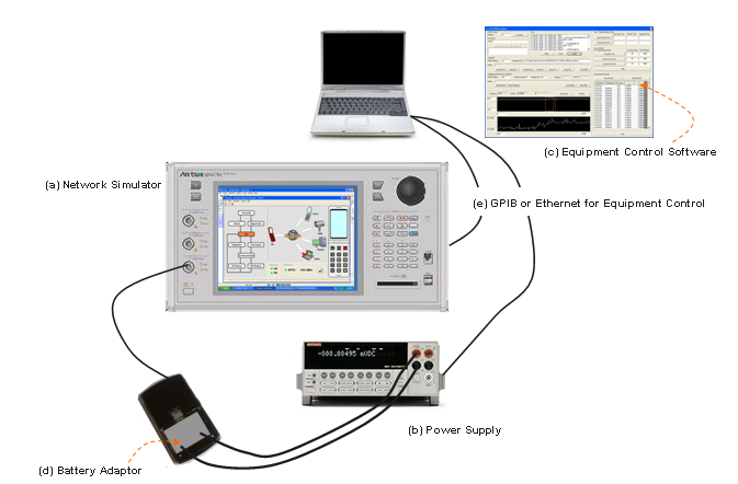
Let's think about each components of the setup. I am not saying you have to use the exact same equipment and same configuration, but I hope this can be a useful guideline for you.
(a) Network Simulator
This is the equipment that can simulate Basestation( NodeB or eNodeB) and some additional core network capability that can cover up to RRC, NAS and data transaction.
I haven't seen many company who purchased this kind of expensive equipment only for battery life test. In most case, they are reusing whatever network simulator they already have. So if you have only one kind of Network Emulator, you wouldn't have any choice, you just have to utilize it as much as possible.
If you have several different type of network simulator in your company and have choices to select, you have to think of which type of network simulator would be the best fit before you start setting up the test system.
Most of the network simulator is designed to perform various tests for 3GPP conformance (RF or Protocol) test. So if the equipment is too much restricted to conformance test without much possibility of extending the functionality, it may not be best fit for the battery life testing. I would recommend you to chose such an equipment that would give you as much flexibility (possibility of extending functionalities) as possible. In many cases, extending functionality of the equipment would mean a lot of extra work(e.g, creating/modifying the protocol stack of the equipment or doing a lot of GPIP programming), but once you do the extrawork and automate the process, it could save a lot of extra work for many other people.
(b) Power Supply
In battery life testing, the importance of Power Supply is very high. The Power Supply in Battery Life Testing should be able to display both voltage and current being drained by DUT and transfer the values to PC on real time basis.
In some case, UE chipset changes the mode of operation in very short amount of duration and repeat the process (e.g, sleeping mode -> wake up mode -> sleeping mode) in very short time period (e.g, several miliseconds time scale). So following features can be important selection criteria.
i) How often the power supply can measure current (or voltage) ? i.e, what is the max sampling rate ?
ii) How quickly it can send the data to control PC ?
iii) How much measurement data can be stored in the power supply ? i.e what is the max data storage ?
If you want to measure very detailed current consumtion changes (e.g, current changes in every miliseconds or so), you should have very large storage capability within the power supply since it is almost impossible to get these values from the control PC on real time basis. If the total measurement time is short it wouldn't be a problem, but if you want to measure all of these data (data per one or a few miliseconds) for a long time (e.g, several minuites to 30, 40 minutes), it would be very tricky. I haven't seen any power supply that can store this amount of data. So you would need some trade off between measurement interval and total measurement time when you select the power supply.
If you are interested in measuring the average current consumption over a long period (i.e over several minutes or hours) the sampling rate may not be so important, but if you want to measure the current consumption in very detail (e.g, very detailed power profile during cell scanning or during DTX, DRX period, you may need the power supply with very high sampling rate).
(c) Equipment Control Software
There are many test that can be done manually (i.e, manually pressing buttons on the equipment and write down the measured value) but Battery Life Test is not the thing that can be done manually since most of the test involves reading the current value with a fraction of second and do this for a long time.
In many case it would be you who has to do the automation programming unless you purchase a whole system designed and sold for battery life test.
But a good news is that the programming for Battery life testing would be much simpler than other types of test (e.g, RF or Protocol Conformance Test).
(d) Battery Adaptor
This is a small thing, but it may be a most critical component to enable or disable you to perform the test or not. As you see in the test setup picture, the UE battery port should be directly connected to the power supply. For this, you would need a specially designed adaptor which is fit into UE's battery slot and has a pair of extention cable which can be connected to the power supply.
If you are working at a UE maker and try to test your own UE, it would be easy to get these adaptors, but if you are in the position to test a radomly selected commercial UEs which is not yours, getting this kind of adaptor would be the most tricky part to setup the test system.
Since there are too many different way or condition to test Battery life, it is all up to you how to configure the Network Simulator and UE application for the test. Sometimes this kind of 'no fixed standard' would make us feel discomfort. Especially if you are not so adventurous in engineering and prefer simple 'button pressing' type of person -:).
From the GSMA document that I linked above, I found a set of very practical guidelines for the parameter selection and I fully agree with this guide line.
- Representative of real network deployment
- Capable of being produced with a minimum amount of test equipment
- Use only features present on existing test equipment
- Define available options unambiguously
Following is the whole set of paramters described in GSMA TS09. I merged several tables from the document into a big table as follows. This may not be all the possible parameters you need for the test and you don't need to use all of these parameters either, but can be an excellent guide for your test. I strongly recommend you to go through all of these parameters and think about practical meaning of each parameters.
|
Scenario |
Operation Mode |
|
|
Standby Time |
Dual mode GSM/WCDMA |
|
|
Dual mode GPRS/WCDMA |
||
|
Dual mode WCDMA/(GSM/GPRS) |
||
|
Dual mode Cellular/WLAN |
||
|
Talk Time |
Circuit Switched |
Dual mode GSM/WCDMA |
|
Dual mode WCDMA/GSM |
||
|
Dual mode Cellular / WLAN |
||
|
Connection Time |
Packet Switched |
Dual mode GPRS/WCDMA |
|
Dual mode WCDMA/GPRS |
||
|
Dual mode Cellular/WLAN |
||
|
Circuit and Packet Switched Simultaneously |
Dual mode GSM/WCDMA |
|
|
Dual mode GPRS/WCDMA |
||
|
Dual mode WCDMA/(GSM/GPRS) |
||
|
Dual mode Cellular/WLAN |
||
|
Browsing |
WAP 1.x |
|
|
WAP 2.x |
||
|
iMode |
||
|
HTML |
||
|
Interface connection |
|
IrDa (PSD) |
|
Bluetooth (PSD) |
||
|
Bluetooth (CSD) |
||
| USB Cable (PSD) | ||
| USB Cable (CSD) | ||
| Extra Software | Java Use |
Download |
|
Games |
||
|
Internal application |
||
|
Music player |
||
|
Voice recorder |
Memo function |
|
|
MP3 player |
Audio playback of previously downloaded file |
|
|
FM radio |
Reception of standard FM signals |
|
|
Multimedia |
Camera Usage |
|
|
Video telephony |
WCDMA | CSD |
| PSD | ||
|
Audio Streaming |
CSD | |
| PSD | ||
|
Standard |
Parameters |
Scope |
| Common |
Ambient Temperature |
|
|
PLMN |
||
|
Backlight |
||
|
SIM |
||
|
Keypad |
||
|
Cell broadcast |
||
|
Additional services |
||
|
System Information 13 |
||
| GSM |
BCCH |
Standby Time |
|
RX level |
Standby Time |
|
|
Cell Reselection |
Standby Time |
|
|
Paging interval |
Standby Time |
|
|
No of neighbour cells declared in the BA_LIST |
Standby Time |
|
|
Cell broadcast |
Standby Time |
|
| GPRS | Most of GSM Parameters |
Standby Time |
|
Network Mode of Operation |
Standby Time |
|
|
Paging channel |
Standby Time |
|
|
Paging interval |
Standby Time |
|
|
Hopping |
Talk Time Test | |
|
Hopping sequence |
Talk Time Test | |
|
Handover |
Talk Time Test | |
|
Rx level |
Talk Time Test | |
|
Handset Tx Level |
Talk Time Test | |
|
Uplink DTX |
Talk Time Test | |
|
Call Mode (=Continuous) |
Talk Time Test | |
|
Codec |
Talk Time Test | |
|
Multi-slot class |
Talk Time Test | |
|
Handset type |
Talk Time Test | |
|
Slots (uplink) |
Talk Time Test | |
|
Slots (downlink) |
Talk Time Test | |
|
Duty cycle |
Talk Time Test | |
|
Coding scheme |
Talk Time Test | |
|
CS can change |
Talk Time Test | |
|
Transfer mode |
Talk Time Test | |
|
Non Transparent |
Talk Time Test | |
|
Retransmissions |
Talk Time Test | |
| WCDMA |
Cell Reselection |
Standby Time |
|
Cell Broadcast |
Standby Time |
|
|
Additional services |
Standby Time |
|
|
Serving Cell UARFCN (Downlink) |
Standby Time, Talk Time Test |
|
|
Serving Cell UARFCN (Uplink) |
Talk Time Test |
|
|
Number of neighbours declared in the BA_LIST |
Standby Time |
|
|
Neighbour cells on different frequency |
Standby Time |
|
|
Serving Cell Scrambling Code |
Standby Time, Talk Time Test |
|
|
Secondary Scrambling Code (Use, No Use) |
Talk Time Test |
|
|
Neighbour cell scrambling codes |
Standby Time |
|
| Fixed Channelization Code (Yes, No) |
Talk Time Test |
|
|
Paging Interval |
Standby Time |
|
|
Periodic Location Update (T3212) |
Standby Time |
|
|
Number of Paging Indicator per Frame (Np) |
Standby Time |
|
|
Ioc |
Standby Time |
|
|
Ior/Ioc |
Standby Time |
|
|
CPICH_RSCP (Ec) |
Standby Time |
|
| PICH Ec/Ior |
Standby Time |
|
| S_IntraSearch |
Standby Time |
|
| S_InterSearch |
Standby Time |
|
| Q_qualmin |
Standby Time |
|
| Q_rxlevlmin |
Standby Time |
|
| SSEARCH_RAT |
Standby Time |
|
|
Serving cell code power (DPCH_Ec/Ior) |
Talk Time Test |
|
|
Ec/No |
Talk Time Test |
|
| Hard Handover |
Talk Time Test |
|
| Soft/Softer Handover |
Talk Time Test |
|
| Radio Bearer Type |
Talk Time Test |
|
|
CPICH_RSCP (Ec) |
Talk Time Test |
|
|
Serving cell code power (DPCH_Ec/Ior) |
Talk Time Test |
|
|
Ec/No |
Talk Time Test |
|
|
Uplink DTX |
Talk Time Test |
|
|
Handset Tx level |
Talk Time Test |
|
| LTE (FDD) |
Serving Cell Downlink EARFCN |
Standby Time,Packet Comm |
|
Serving Cell uplink EARFCN |
Packet Comm | |
|
Number of neighbours declared in the neighbour cell list |
Standby Time,Packet Comm |
|
|
DRX Cycle |
Standby Time |
|
|
Periodic TAU (T3412) |
Standby Time |
|
|
Reference Signal Energy Per Resource Element (RS EPRE) |
Standby Time,Packet Comm |
|
|
PBCH EPRE Ratio |
Standby Time,Packet Comm |
|
|
PSS EPRE Ratio |
Standby Time,Packet Comm |
|
|
SSS EPRE Ratio |
Standby Time,Packet Comm |
|
|
PCFICH EPRE Ratio |
Standby Time,Packet Comm |
|
|
PDCCH EPRE Ratio |
Standby Time,Packet Comm |
|
|
PDSCH EPRE Ratio |
Standby Time,Packet Comm |
|
|
PHICH EPRE Ratio |
Standby Time,Packet Comm |
|
|
Serving cell bandwidth |
Standby Time |
|
|
Number of antenna ports at eNodeB |
Standby Time |
|
|
Cyclic Prefix Length |
Standby Time |
|
|
PHICH Duration |
Standby Time |
|
|
PDCCH length |
Standby Time,Packet Comm |
|
|
DCI Aggregation Level |
Standby Time,Packet Comm |
|
|
Qrxlevmin |
Standby Time |
|
|
Sintrasearch |
Standby Time |
|
|
Paging and System Information change notification on PDCCH |
Standby Time |
|
|
System Information Reception |
Standby Time |
|
|
OCNG |
Standby Time, Packet Comm |
|
|
RoHC |
Packet Comm |
|
|
UL TX Power level |
Packet Comm |
|
|
DL Transmission Mode |
Packet Comm |
|
|
Cyclic Prefix Length |
Packet Comm |
|
|
PHICH Duration |
Packet Comm |
|
|
DCI Aggregation Level |
Packet Comm |
|
|
DRX Configuration |
Packet Comm |
|
| UL/DL Channel Bandwidth |
Packet Comm |
|
|
Allocated resource blocks in DL |
Packet Comm |
|
|
TBS Index in DL |
Packet Comm |
|
|
Allocated resource blocks in UL |
Packet Comm |
|
|
TBS Index in UL |
Packet Comm |
|
| WLAN/AP |
WLAN standards |
Standby Time |
|
WiFi frequency |
Standby Time |
|
|
Authentication / Ciphering |
Standby Time |
|
|
DTIM period |
Standby Time |
|
|
WMM/UAPSD power save |
Standby Time |
|
|
WiFi RSSI |
Standby Time |
|
|
Beacon interval |
Standby Time |
|
| WLAN/DUT |
WLAN standards |
Standby Time |
|
Long Retry Limit |
Standby Time |
|
|
Short Retry Limit |
Standby Time |
|
|
RTS threshold |
Standby Time |
|
|
TX Power Level |
Standby Time |
|
|
WiFi Network Scan Period |
Standby Time |
|
|
WiFi Device Tx level |
VoIP |
|
|
Audio duty cycle |
VoIP |
|
| GAN /WLAN,GSM |
Keep alive timer |
Standby Time |
|
ESP rekeying (IPSec) |
Standby Time |
|
|
IKE rekeying (IPSec) |
Standby Time |
|
|
RTP/UDP packet sample size |
VoIP |
|
|
Channel mode |
VoIP |
|
|
Speech codec rate |
VoIP |
According to my experience and some interview with other customers, the measurement result based on GSMA condition doesn’t make much difference in terms of current consumption, so many engineers start losing appetite of this kind of testing. And they started to investigating other factors with more influence on current consumption (Battery Life). Some of these factors in UMTS case can be as follows.
i) Sreen On/Off (in case of mobile phone, smart phone)
ii) DRX cycle (in IDLE mode)
iii) Current consumption during cell selection/reselection
iv) Current consumption during Handover
v) DRX/DTX in connected mode (UMTS Rel 7 and higher)
vi) RRC State Changes (Cell DCH -> FACH -> PCH)
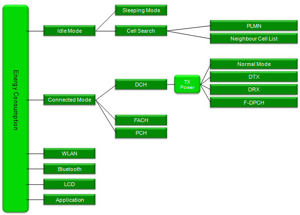
Since there can be so many different combination of UE status for the energy consumption, my recommendation is to create a kind of tree diagram for your test plan first. One of my personal example is as follows. This is for WCDMA and is very much simplified one. Basic idea still based on GSMA criteria and with a little modification. You may have your own criteria and different shape of the tree.
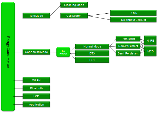
Following is a possible example for LTE case. Again, this is only one example and you may come up with your own plan depending on your device implementation.
But this cannot be the full list of factors and there would be various other types of factors. There may be many factors which are specific to each customer. So it is almost impossible to develop a general purpose battery life testing tools that can meet everybody’s requirement. (One possibility is to develop a customer specific tools (e.g, a tool for a specific system operator) based on the requirement from the customer if they can clearly define those requirement).
Here goes an example where you can see what kind of factors can be considered for battery life (energy consumption).
Major factors that drains the current
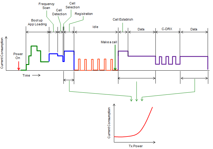
Following illustration is overal mobile phone structure (above 10000 feet view) in terms of energy consumption based on my personal test experience. The red part is the portion that drains the current the most, Green part is the second and Blue part is the third, Violet parts would be the last. When you are investigating energy consumption especially with those parameter changes listed in previous section (Test by Practice), it would be helpful if you can correlate which parameters (factors) are related to which components in the following diagram. If you have clear understanding on these correlations, you may have rough estimation of energy consumption at a specific condition (parameter set) even without doing any measurement.
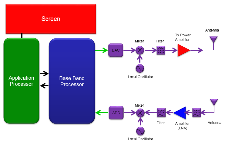
For example, if you change UE Tx power with keeping all the other parameters fixed and then measure current consumption, you would see huge range of variations of energy consumption depending on Tx power. Those energy consumption is mostly caused by Tx Power Amplifier. So if you are in the position of optimizing the energy consumption of the device, you should check first on Amplifier efficiency and how well the amplifier configuration is optimized. Recently to minimize the current consumption by amplifier some manufacturer support special techniques called Average Power Tracking or Envelop Power Tracking.
If you change number of RBs or System Bandwidth with all other parameters (e.g, UL Power, DL power, No IP application running), you are changing the factors related only to baseband processor. In this case, you may not see any drastic variation of measurement result. Based on my experience, I saw almost no changes in current consumption in terms of UL RB allocation. I saw almost no changes of current consumption even with extreme cases of 1 RB vs 50 RBs in 10 Mhz system bandwidth. In case of downlink, I saw a certain range of current consumption changes in terms of RB. With one experiment that I did, I saw around 40~50 mA current consumtion variation between 1RB and 50RB.
I think the most tricky things about current consumption measurement is to control various applications (application layer program) running on UE. You would see pretty wide range of measurement result depending on what kind of application running on the device. Especially on many Smart phone, there are many applications you don't even recognize that those are running on the background. So if you need to accurate measurement, it would be good trick to test the device in test mode which requires UE to disable application layer program or let UE stay untouched for some time (a couple of mins) before you start measurement. Usually if you put UE untouched for a couple of mins most of unncessary application stop running and you would have relatively good baseline for the measurement. However, this is not guaranteed though.
If you are taking on the measurement under the condition that Radio Protocol factors and Application layer conditions are combined, for example testing with IP layer application, you should be very careful of testing and interpreting the result. For example, I mentioned that Number of RB does not influence much on current consumption but when you change the number of RBs with IP layer throughput (or any other application layer causing U-plane traffic) you may see much wider variation with number of RB. In this case, those variation may be due to Application and AP Core chipset involvement which would show wider range of current consumption depending on how much data they process. So for this kind of testing, I recommend you to take the measurement without application layer involvement and get the accurate baseline and then try with application running with application and compare the two result to find which part (radio stack or application stack) is dominant contributer of the current consumption. Also, I recommend you to take instantaneous current consumption rather than average current consumption at least for inititial investigation or troubleshooting situation (Refer to Average vs Instantaneous Measurement)
In a device (e.g, smartphone), diverse activities are happening in side not only during the connected mode but also during the idle mode. Those activities are so diverse that it would be almost impossible to measure the current consumption separately for each and every activities. However, there are several activities which takes the most of time of UE activities or become the basis of other complicated activities. So if you have measured result of those fundamental activities, you would be able to get pretty good estimation of current consumptions for other activities without doing any real measurement.
Let's think about the most fundamental activities during the idle mode. In most of the time during idle mode, UE is in sleep mode consuming the minimum amount of energy, but UE has to wake up periodically mainly for detecting any Paging message. So the current consumtion while UE is in sleep mode and the current consumption during the wake up is the most fundamental data for idle mode current consumption which determine the stand-by battery life.
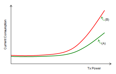
In connected mode in which UE receives and transmit user data, UE normally wake up all the time and consumes the largest amount of energy. According to the test from various sources, the energy consumption by data reception is not that huge comparing to the energy consumption by data transmission. It is also shown in many test, data tranmission power plays more important role than the data rate in terms of current consumption. Therefore, the current consumption measurement for each UE transmission power can be a very good fundamental data for UE connected mode energy consumption assessment. For example, if you got the two current measurement curve for the two different devices as shown below, you would say 'Device (A)' is much more efficient than the device (B) in terms of current consumption.
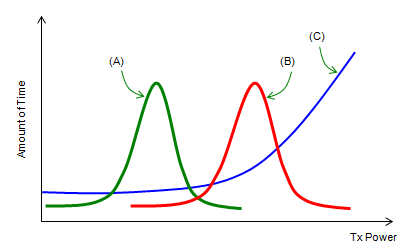
In real life, UE transmission power is not stay at the same value all the time or just linearly increase or decrease. In most case, the transmission power keep changes which can only be described by statistical distribution. Some example of statistical distribution of UE transmission power can be illustrated as below (Of course, real distribution would not be as smooth and clean as in this illustration).
When you do voice call or low data rate packet communication in a relatively good network coveragy, you may get the profile like (A) at which UE transmission power stays around a relatively low value.
When you do voice call or low data rate packet communication in a relatively poor network coveragy, you may get the profile like (A) at which UE transmission power stays around a relatively high value.
When you do some high data rate packet transmission, it is highly probable that the distribution goes like (C).
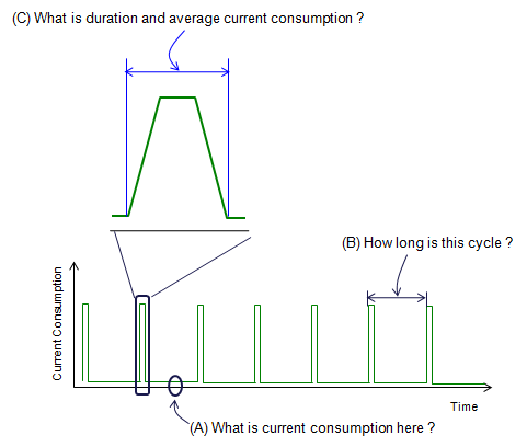
Now let's think of more realistic situation. Following is an imaginary situation showing almost all the possible activities from power on through call setup/data communication. But in reality, it would not be easy to get the meaningful and repeatable current measurement result for this kind of situation, mainly because the sequence and duration of each activity may vary everytime you try. So the most practical way of testing would be to measure the current consumption for each of these status for a certain time period (e.g, 1 cycle or a couple of seconds) and extend the number for each case that really happens. For example, if you have the current measurement for data transmission for 1 sec (let's call this a 'reference value') and the UE transmitted the data for 10 seconds in real application, just multiplying 10 to the 1 second reference value will give you the total current consumption for the real application.
Average vs Instant Measurement
In conventional current consumption measurement, we measured average current consumption over a certain period in almost every test cases. Taking the average current consumption has some advantages as follows
- Fast : Due to less sampling requirement
- Low Cost : In most case, you don't need to have equipment that require very high sampling rate and high cost
- Easy Automation : It is easy for automate the test since you only have to poll a couple of results with long interval and almost no need for sophisticated data processing.
This kind of average current measurement were OK with conventional technology (like 2G or early 3G) in which radio protocol is relatively simple and not so diverse higher layer applications running on the device (simply put, features phones using old 2G/3G).
However with the introduction of LTE and Smartphones, everything (Radio protocol, application layer activities) has become complicated and conditions affecting the current consumption very dynmically in very short interval (e.g, TPC intervals, dynamic RB allocations, Connected Mode DRX etc). Average current consumption is losing its ground. Especially when you need any troubleshooting or root cause analysis of current consumption, average measurement is almost of no help.
Let's take a look at a couple of examples.
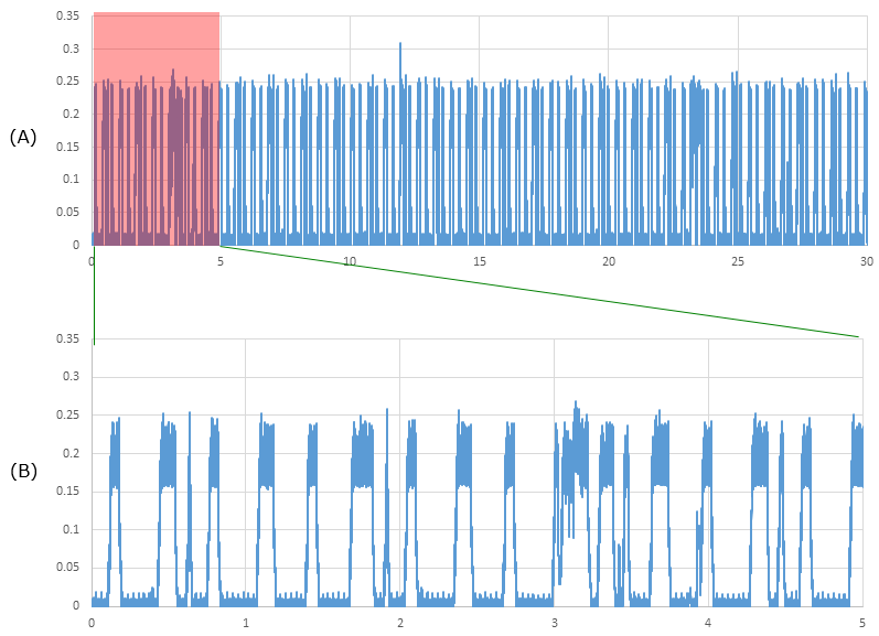
Following is an example of instataneous current consumption measurement during the idle mode. In (A), most of the idel mode spike looks pretty similar to each other. But if you expand it a little bit as in (B), you would notice various different pulse/spikes with various different width. Depending on how these various spikes combines, you may get different average measurement value.. but you would not figure out why you are getting those different measurement difference if you are taking average values only. In most case, the width of the pulse is not random and each of those width variation is related to meaningful UE protocol and they would vary with USIM, PLMN, SIB configuration and Neigbhour cell status etc. If you analyze the detailed UE and correlate the UE activities with each of the spikes, you would recognize UE side actvities just by looking at the current consumption pattern.
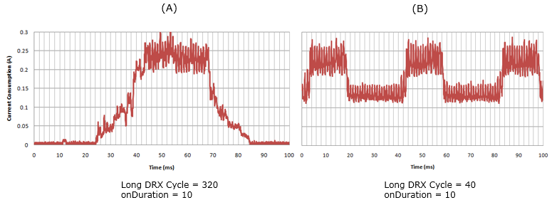
Following is an example of instantaneous current consumption measurement during a connected mode DRX in LTE. As you see here, onDuration value is same between (A) and (B). But the current consumption pulse width is drastically different between (A) and (B). Also, you would see the drastic different on baseline (current consumption during sleep mode). Is this difference from DRX Cycle difference ? Yes. The general tendency that I have seen is that the longer DRX cycle is set (i.e, the longer sleeping time it has), the radio stack can get into deep sleep mode so baseline during the sleep mode gets lower (almost to the level of idle mode), but if radio stack does not have enough time to get into the deepsleep mode before next wakeup cycle, it just gets into shallow sleep mode which consumes relatively large amount of current. There are a lot of rooms for optimization here. If you are taking the average measurement, you are losing all these details.
Analysis of Battery Characteristics
In most better life testing, we use Power supply in stead of real battery as described in Test Setup section. It is very useful to quantify various measurement and see the suptle changes of current consumption (e.g, current consumption changes by paging signal monitoring, current consumption changes between sleeping mode and normal mode etc). But there can be some drawback of this method. In real battery, most of battery characteristics changes with various conditions as shown below (especially with temperature and SoC=State of Charge), but it is very difficult to configure this kind of condition with power supply.
In this case, I think old test method would help in some degree. Use real battery, do a lot of operations and how long the batter last. Of course, it would be a little difficult to quantify the test result with this kind of method. So I don't think you can completely replace the power supply method with this method, but I recommend to do this kind of test as a complimentary test.

IEEE TRANSACTIONS ON ENERGY CONVERSION, VOL. 21, NO. 2, JUNE 2006
Accurate Electrical Battery Model Capable of Predicting Runtime and I–V Performance
Min Chen, Student Member, IEEE, and Gabriel A. Rinc´on-Mora, Senior Member, IEEE
For the detailed analysis of Battery characteristics, refer to the paper listed above.
Factors affecting Battery Capacity
- Cutoff Voltage
- Temperature
- Discharge Current
- Shelf life
- Self Discharge
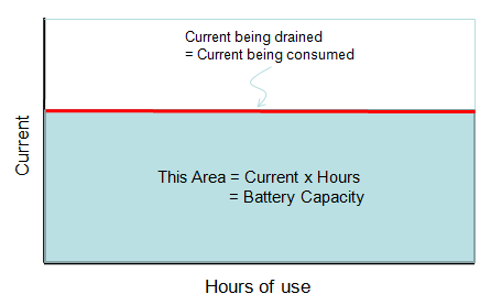
Battery Capacity : Battery Capacity is an indicator to show how much engergy is stored in a battery and it is measured in Ampere-Hours (Ahr), mili Ampere-Hours (mAhr) or kilowatt-hours(kWh) or watt-hours(Wh).
For example, if the capacity of a battery is 1000 mAh. It means that if you use it for the system that is draining the current at 20 mA, it will last 50 hours. (20 mA x 50 Hours = 1000 mAh).
Discharge Curve :
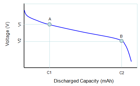
Cutoff Voltage : Cutoff voltage is the specific voltage where you should not discharge any more. It may not the point where there is no remaining capacity meaning it may still have some remaining capacity, but your device may not work properly if the voltage of the battery goes below the cutoff voltage.
In practice, if you see the battery gauage on your laptop or your mobile phone goes to the bottom, it may signal you that your battery voltage reached the cutoff voltage and you should recharge the battery.
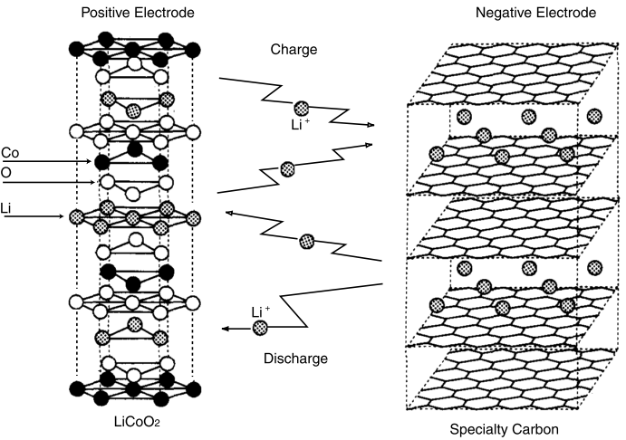
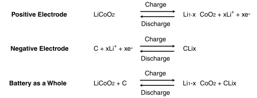
< Lithium Ion >
[1] How we test: Cell phones and smartphones
[2] Battery Performance Characteristics
[3] Energy Impact of Emerging Mobile Internet Applications on LTE Networks: Issues and Solutions (pdf)
[4] Google's Colt McAnlis "The Hard Things about the Internet of Things" - ARM TechCon 2015