The Service Request procedure in 5G is used when a device wants to establish a connection to the AMF. There are two possible scenarios in which this can happen: Network Triggered and UE Triggered Request. In practice, I think UE triggered Request is more common.
In more formal expression as stated in 24.501-5.6.1.1, 'The purpose of the service request procedure is to change the 5GMM mode from 5GMM-IDLE to 5GMMCONNECTED mode.' as highlighted in the following statemachine.
< 24.501 Figure 5.1.3.2.1.1.1: 5GMM main states in the UE >
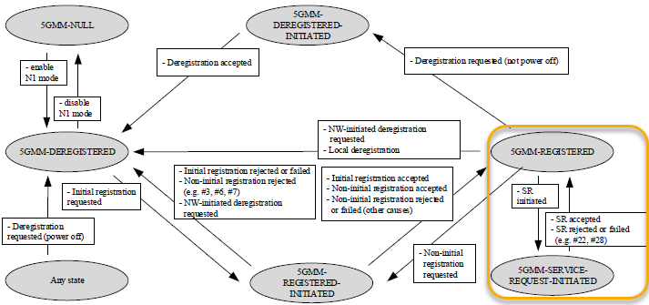
In this note, I will talk about the details of Service Request procedure as follows.
- What triggers UE initiated Service Request ?
- What triggers Network initiated Service Request ?
- Signaling Sequence
- < Case A > Normal Service Setup
- < Case B > No Service Accept
- < Case C > SERVICE REJECT
- What else is on the air around a Service Request ?
- Message Structure
- Reference
What triggers UE initiated Service Request ?
When UE is supposed to trigger Service Request ? The most common case is when there is some data to be sent by UE while it is in idle mode, UE initiate the service request.
More detailed case description for UE initiated Service Request is stated in 24.501-5.6.1.1 as follows : (NOTE : The first two cases would be the most common cases you would see in regular operations)
- the UE has uplink signalling pending over 3GPP access and the UE is in 5GMM-IDLE mode over 3GPP access
- the UE has user data pending over 3GPP access and the UE is in 5GMM-IDLE or 5GMM-CONNECTED mode over 3GPP access;
- the UE has user data pending over non-3GPP access and the UE is in 5GMM-CONNECTED mode over non-3GPP access;
- the UE in 5GMM-IDLE mode over non-3GPP access, receives an indication from the lower layers of non-3GPP access, that the access stratum connection is established between UE and network, if T3346 is not running;
- the UE in 5GMM-IDLE or 5GMM-CONNECTED mode over 3GPP access receives a request from the upper layers to perform emergency service fallback and performs emergency services fallback
- the UE has to request resources for V2X communication over PC5.
The six cases above are not six variants of one situation. In most of them the UE is in 5GMM-IDLE mode, so the service request has to re-establish the NAS signalling connection first. In the second case the UE may already be in 5GMM-CONNECTED mode. Then the NAS signalling connection is already established, and the service request only asks for the user plane of one or more PDU sessions.
The IE that carries that second request is Uplink data status. The UE sets one bit per PDU session that has pending uplink data and no user plane resource. The network reads the bitmap and re-establishes only those sessions. That is why a SERVICE REQUEST can appear in a log with no preceding RRC connection setup.
Whatever the trigger, the UE behaviour after it is the same. The UE sends the SERVICE REQUEST message, starts T3517, and enters 5GMM-SERVICE-REQUEST-INITIATED. 24.501 Figure 5.1.3.2.1.1.1 shows the transition into that state and the two transitions out of it. One is SERVICE ACCEPT. The other covers a rejected or failed request.
The trigger also decides the value the UE puts in the Service type IE. Pending user data gives "data", and pending uplink signalling gives "signalling". Emergency services fallback gives "emergency services fallback". A UE with high priority access gives "high priority access". The full value list is in the Service Type section of this note.
Idle mode is the common trigger, but not the only one : pending user data can trigger a service request while the UE is already in 5GMM-CONNECTED mode. The NAS signalling connection and the user plane are established separately.Uplink data status names the sessions : the bitmap tells the network which PDU sessions need their user plane resources re-established. The network does not have to restore all of them.The trigger is visible in the Service type IE : reading that one value identifies which of the six cases produced the message.T3517 supervises the whole procedure : it starts with the SERVICE REQUEST and stops on the response. Its expiry is the only sign of a request that was never answered.
What triggers Network initiated Service Request ?
When UE is supposed to trigger Service Request ? The most common case is when there is some data to be sent by Network while it is in idle mode, NW(Network) initiate the service request.
More detailed case description for NW initiated Service Request is stated in 24.501-5.6.1.1 as follows : (NOTE : The first two cases would be the most common cases you would see in regular operations)
- the network has downlink signalling pending over 3GPP access and the UE is in 5GMM-IDLE mode over 3GPP access;
- the network has downlink user data pending over 3GPP access and the UE is in 5GMM-IDLE mode over 3GPP access;
- the network has downlink signalling pending over non-3GPP access, the UE is in 5GMM-IDLE mode over non- 3GPP access and in 5GMM-IDLE or 5GMM-CONNECTED mode over 3GPP access
- the network has downlink user data pending over non-3GPP access, the UE is in 5GMM-IDLE mode over non-3GPP access and in 5GMM-IDLE or 5GMM-CONNECTED mode over 3GPP access
One detail is easy to miss in the list above. The network has no SERVICE REQUEST message of its own to send. Over 3GPP access it pages the UE. Over non-3GPP access it sends a NOTIFICATION message. The UE then runs the same service request procedure. So every SERVICE REQUEST seen on the air interface is sent by the UE, whichever side had the pending data.
That leaves one marker to separate the two triggers in a log. A UE answering paging sets the Service type IE to "mobile terminated services". A UE with its own pending traffic sets "data" or "signalling" instead. The rest of the message looks the same in both cases.
The same distinction explains the empty NW Timer column in the Signaling Sequence tables. The network side of a service request runs no timer of its own, because the network is waiting for an answer to something it sent earlier. The timers belong to that earlier message instead. T3513 supervises paging, and T3565 supervises the retransmission of NOTIFICATION. Both stop as soon as the UE responds.
The last two cases pair a non-3GPP state with a 3GPP state, and the pairing is the point. The UE is not reachable over the non-3GPP leg, so the network uses the 3GPP leg to deliver the notification. The UE then answers over the access the network chose.
The network triggers, and the UE sends : paging over 3GPP access and NOTIFICATION over non-3GPP access are the network half of the procedure. The SERVICE REQUEST message itself always comes from the UE."Mobile terminated services" is the marker : that Service type value separates a paging response from a UE originated request in a log.The network timers belong to the trigger : T3513 supervises paging and T3565 supervises notification. That is why the NW Timer column of the Signaling Sequence tables stays empty.A non-3GPP trigger can arrive over 3GPP access : the network delivers the notification over whichever leg is reachable, so the two accesses have to be read together.
Signaling Sequence
Three outcomes are worth separating before reading the tables. The request is accepted, the request is answered by nothing at all, or the request is refused with a cause value. The first two produce almost the same log until a timer expires. T3517 is what separates them. In the third case the cause value decides everything the UE does next.
According to 24.501 - 5.6.1.1 Service Setup procedure initiation goes as follows.
|
Direction |
Message |
UE Timer |
NW Timer |
|
UE -> NW(AMF) |
SERVICE REQUEST |
T3517 Start |
|
|
UE <- NW(AMF) |
SERVICE ACCEPT |
T3517 Stop |
|
|
Direction |
Message |
UE Timer |
NW Timer |
|
UE -> NW(AMF) |
SERVICE REQUEST |
T3517 Start |
|
|
UE <- NW(AMF) |
No SERVICE ACCEPT |
T3517 Expire |
|
|
Direction |
Message |
UE Timer |
NW Timer |
|
UE -> NW(AMF) |
SERVICE REQUEST |
T3517 Start |
|
|
UE <- NW(AMF) |
SERVICE REJECT |
T3517 Stop |
|
The three tables describe the same two message slots, and they differ only in what fills the second one. Placing them side by side makes the role of T3517 easier to see. The timer starts on the SERVICE REQUEST in every case. What changes is whether a response stops it, and which response that is.
Figure 1. The three cases differ only in the second message. T3517 is started by the SERVICE REQUEST in all of them, so the timer rather than the message is what separates a refused request from an unanswered one.
Case A : SERVICE ACCEPT arrives and T3517 is stopped. The UE returns to 5GMM-REGISTERED, and the PDU session status IE in the response confirms which sessions the network agrees are active.Case B : nothing arrives and T3517 expires. There is no cause value, so the UE has nothing to act on beyond the abnormal case handling of 24.501-5.6.1.Case C : SERVICE REJECT arrives with a 5GMM cause value, and T3517 is stopped. The cause decides whether the UE retries, registers again, or disables N1 mode.The UE side carries the only timer : all three cases start and end T3517 at the UE. That is why the NW Timer column stays empty in every table.
Following is a table listing various reject cause and the expected UE behavior based on 24.501-5.6.1.5 and 24.501-AnnexA. I put only high level and most critical (most critical to me) in the 'Expected UE behavior' column. There are much more futher details specified in the specification.
|
Reject Cause |
Expected UE Behavior |
|
#3 (Illegal UE); or #6 (Illegal ME). |
|
|
#7 (5GS services not allowed) |
|
|
#9 (UE identity cannot be derived by the network) |
|
|
#10 (Implicitly de-registered) |
|
|
#11 (PLMN not allowed) |
|
|
#12 (Tracking area not allowed) |
|
|
#13 (Roaming not allowed in this tracking area) |
|
|
#15 (No suitable cells in tracking area) |
|
|
#22 (Congestion) |
|
|
#27 (N1 mode not allowed) |
|
|
#28 (Restricted service area) |
|
|
#72 (Non-3GPP access to 5GCN not allowed) |
|
|
#73 (Serving network not authorized) |
|
What else is on the air around a Service Request ?
The three case tables show two messages. A real log of the same procedure shows fifteen or more. The SERVICE REQUEST never travels on its own. It is carried inside an RRC message, and then inside an NGAP message, and the SERVICE ACCEPT comes back the same way. Three flows follow, one for each of Case A, Case B and Case C.
Example A follows a UE in 5GMM-IDLE mode with uplink data waiting on PDU session 5. That is the same situation the Example 01 log of the Message Structure section captures. The flow starts at the random access preamble, because the UE has no RRC connection to use yet.
Figure 2 draws the same flow as a ladder. The two NAS messages are drawn in purple, and every other arrow is RRC or NGAP. The distance between those two purple steps is what the drawing is for. Five steps sit between them, and T3517 is running across all five.
Figure 2. One service setup from idle, drawn in full. Only two steps carry a NAS message, and both of them are carried inside an RRC message. That is why a NAS-only log shows two lines for a procedure that crossed the air interface nine times.
# |
Direction |
Message |
What it carries |
1 |
UE -> gNB |
PRACH preamble (MSG1) |
The random access attempt. Nothing but the preamble index. |
2 |
UE <- gNB |
Random Access Response (MSG2) |
Timing advance, an uplink grant and a TC-RNTI. |
3 |
UE -> gNB |
RRCSetupRequest (MSG3) |
establishmentCause set to mo-Data, and the UE identity. |
4 |
UE <- gNB |
RRCSetup (MSG4) |
The SRB1 configuration. |
5 |
UE -> gNB |
RRCSetupComplete |
The SERVICE REQUEST, in the dedicatedNAS-Message field. Also registeredAMF and the S-NSSAI list. |
6 |
gNB -> AMF |
NGAP INITIAL UE MESSAGE |
The same NAS PDU, the RRC Establishment Cause and the User Location Information. |
7 |
AMF |
(internal) |
The AMF verifies the integrity of the SERVICE REQUEST against the stored 5G NAS security context. It then asks the SMF to activate the user plane of PDU session 5. |
8 |
gNB <- AMF |
NGAP INITIAL CONTEXT SETUP REQUEST |
The security key and the UE security capabilities, the PDU Session Resource Setup List for session 5, and the SERVICE ACCEPT as the NAS-PDU. |
9 |
UE <- gNB |
SecurityModeCommand |
The AS integrity and ciphering algorithms. |
10 |
UE -> gNB |
SecurityModeComplete |
Nothing. AS security is active from here on. |
11 |
UE <- gNB |
RRCReconfiguration |
The SRB2 and DRB configuration, and the SERVICE ACCEPT in the dedicatedNAS-MessageList field. |
12 |
UE -> gNB |
RRCReconfigurationComplete |
Nothing. The radio bearers are in place. |
13 |
gNB -> AMF |
NGAP INITIAL CONTEXT SETUP RESPONSE |
The gNB tunnel endpoint the UPF sends downlink data to. |
14 |
UE <-> NW |
User data on PDU session 5 |
The traffic the whole procedure was run for. |
SERVICE ACCEPT is not a message of its own on the air : the AMF hands it to the gNB inside NGAP INITIAL CONTEXT SETUP REQUEST. The gNB then delivers it inside RRCReconfiguration.The two example logs differ in their security header : the SERVICE REQUEST is an initial NAS message. 24.501 sends such a message integrity protected, with the cleartext IEs only. It also repeats the complete message inside the NAS message container. That repetition is what the Example 01 log shows. The SERVICE ACCEPT is not an initial message, so it is ciphered as well.T3517 covers the AS setup, not only the NAS exchange : the timer runs while SecurityModeCommand and RRCReconfiguration are exchanged. A slow context setup at the gNB can expire it just as a lost NAS message can.The establishment cause and the Service type should agree : mo-Data in RRCSetupRequest goes with "data" in the Service type IE, and mt-Access goes with "mobile terminated services". A mismatch is worth checking before anything else in the log.
Example B is the same flow up to the NGAP INITIAL UE MESSAGE, and then nothing comes back. The common reason is that the AMF cannot verify the integrity of the SERVICE REQUEST. A UE that kept a stale 5G NAS security context across a reboot produces exactly that. The AMF discards the message instead of answering it, so the UE never receives a cause value.
# |
Direction |
Message |
What it carries |
1-4 |
UE <-> gNB |
Random access and RRC connection setup |
Identical to Example A. |
5 |
UE -> gNB |
RRCSetupComplete |
The SERVICE REQUEST, in the dedicatedNAS-Message field. |
6 |
gNB -> AMF |
NGAP INITIAL UE MESSAGE |
The same NAS PDU. |
7 |
AMF |
(internal) |
The integrity check on the SERVICE REQUEST fails, or no 5G NAS security context matches the 5G-S-TMSI. 24.501 lets the AMF discard a NAS message that fails its integrity check. |
8 |
- |
(nothing is sent) |
No NGAP INITIAL CONTEXT SETUP REQUEST leaves the AMF, so nothing reaches the UE. T3517 keeps running. |
9 |
UE |
(internal) |
T3517 expires. The UE aborts the service request procedure and stays in 5GMM-REGISTERED. |
10 |
UE <- gNB |
RRCRelease |
The gNB releases the connection on its own inactivity supervision, because no context setup ever arrived. |
11 |
UE -> gNB |
RRCSetupRequest, or a registration procedure |
The retry. A fresh registration is what rebuilds the security context when that was the cause. |
The missing NGAP message is the marker : a piggybacked SERVICE ACCEPT and a genuine Case B look the same in a NAS-only log. The check that separates them is whether NGAP INITIAL CONTEXT SETUP REQUEST was ever sent.No cause value means no instruction : the reject cause table of this section does not apply here, so the UE has only the abnormal case handling of 24.501-5.6.1 to follow.A stale security context is the common cause : the UE treats its context as valid and the AMF does not hold it. Only a new registration procedure resolves that.The release is driven by inactivity, not by the failure : the gNB cannot see a T3517 expiry, so it has no reason to act on one. The connection is released by inactivity supervision instead.
Example C is the same request, refused. The AMF is applying congestion control, so it answers with SERVICE REJECT, 5GMM cause #22 and a T3346 value. The reject arrives in a different RRC message than the accept did. That difference is visible in a log without decoding any NAS at all.
# |
Direction |
Message |
What it carries |
1-4 |
UE <-> gNB |
Random access and RRC connection setup |
Identical to Example A. |
5 |
UE -> gNB |
RRCSetupComplete |
The SERVICE REQUEST, in the dedicatedNAS-Message field. |
6 |
gNB -> AMF |
NGAP INITIAL UE MESSAGE |
The same NAS PDU. |
7 |
AMF |
(internal) |
Congestion control selects 5GMM cause #22 and a T3346 value. |
8 |
gNB <- AMF |
NGAP DOWNLINK NAS TRANSPORT |
The SERVICE REJECT as the NAS-PDU. No context setup is requested, because no user plane will be built. |
9 |
UE <- gNB |
DLInformationTransfer |
The SERVICE REJECT, in the dedicatedNAS-Message field. |
10 |
UE |
(internal) |
The UE starts T3346, aborts the procedure and enters 5GMM-REGISTERED. |
11 |
gNB <- AMF |
NGAP UE CONTEXT RELEASE COMMAND |
The AMF asks for the signalling connection to be released. |
12 |
UE <- gNB |
RRCRelease |
The UE returns to RRC_IDLE. |
13 |
gNB -> AMF |
NGAP UE CONTEXT RELEASE COMPLETE |
The N2 context for this UE is gone. |
DLInformationTransfer, not RRCReconfiguration : an accepted request builds radio bearers and a refused one does not, so the RRC message that carries the NAS answer differs between the two cases.The reject arrives before any AS security : no INITIAL CONTEXT SETUP REQUEST is sent, so the gNB never runs SecurityModeCommand. That is why the refused flow is shorter than the accepted one.T3346 outlasts the procedure : the UE stops T3517 at once, and then blocks new service requests until T3346 expires. Emergency services, high priority access and answers to paging are the exceptions.The release is driven by the AMF : UE CONTEXT RELEASE COMMAND follows the reject. A log that ends in RRCRelease immediately after a NAS message is usually a reject rather than a timeout.
Message Structure
Three items are described in this section, and they are not at the same level. Service Request and Service Accept are complete NAS messages. Service type is a single IE carried inside the Service Request. It is listed separately because its value identifies the trigger, and a log is usually read from that value first.
The structure of messages and a specific IE(Information Elements) involved in Service Setup process listed below :
Service Request
The Service Request message is used when a UE in 5G idle/inactive state wants to resume service (to send/receive data or signaling). These IEs provide the network enough information to re-establish the UE’s context, security parameters, and PDU session status. The references (e.g., 24.501-9.11.3.x) point to exact sections in the 3GPP specification where each IE’s encoding and behavior are fully described.
Service Request (24.501-8.2.16.1)
Service request message identity (24.501-9.7)
ngKSI(24.501-9.11.3.32)
Service type(24.501-9.11.3.50)
5G-S-TMSI(24.501-9.11.33.4)
Uplink data status(24.501-9.11.3.57)
PDU session status(24.501-9.11.3.44)
Allowed PDU session status(24.501-9.11.3.13)
NAS message container(24.501-9.11.3.33)
Following is brief description on each of the IEs
- Service Request Message Identity
- A small, fixed code that identifies this NAS message as a “Service Request.” Every NAS message (e.g., Registration Request, Service Request, etc.) has a unique message identity defined in 3GPP TS 24.501 § 9.7.
- ngKSI (NAS key set identifier)
- Identifies which security context the UE (User Equipment) is using. The UE and the 5G core use this identifier to ensure that the correct NAS security keys are applied to protect the message. Reference: 3GPP TS 24.501 § 9.11.3.32.
- Indicates the security context (Key Set Identifier) used for authentication and encryption.
- Service Type
- Indicates the type of service the UE is requesting. Common service types include “Mobile-Terminated data,” “Mobile-Originated signaling,” etc., helping the network understand why the UE wants to resume or establish a connection. Reference: 3GPP TS 24.501 § 9.11.3.50.
- 5G-S-TMSI
- The 5G System Temporary Mobile Subscriber Identity, a temporary ID used to identify the UE within the 5G system. It’s allocated by the 5G core and helps preserve user privacy over the air. Reference: 3GPP TS 24.501 § 9.11.3.4.
- Uplink Data Status
- Conveys which PDU sessions have pending data on the UE side. This tells the network that the UE has uplink traffic buffered and needs resources. Reference: 3GPP TS 24.501 § 9.11.3.57.
- Indicates which PDU (Packet Data Unit) sessions have uplink data pending transmission. A bitmask where each bit corresponds to a PDU session ID (e.g., bit 0 = PDU session 1).
- PDU Session Status
- Lists active PDU sessions from the UE’s viewpoint, letting the network know which sessions the UE still considers active. Reference: 3GPP TS 24.501 § 9.11.3.44.
- Bitmask indicating active sessions (e.g., bit 1 = PDU session 2 is active).
- Allowed PDU Session Status
- Tells the UE which of its requested or active PDU sessions the network is allowing in the current service request procedure (e.g., after a potential restriction). Reference: 3GPP TS 24.501 § 9.11.3.13.
- NAS Message Container
- A container that can carry additional NAS messages or parameters if needed (often used for embedding secondary NAS messages or piggybacking procedures). Reference: 3GPP TS 24.501 § 9.11.3.33.
This is a sample message from the log provided by Amarisoft. Highlights of this message is as follows.
- This message is triggered by the existence of pending data on UE (saying 'I have some data to send'). This is indicated by the IE 'Service Type'.
- The PSI (PDU Session Identifier) for the pending data (data to be sent) is 5. This is indicated by the IE 'uplink data status'
- The PSI (PDU Session Identifier) for the currently active PDU is 5. This is indicated by the IE 'PDU session status'.
Message: Service request
Data:
Protocol discriminator = 0x7e (5GS Mobility Management)
Security header = 0x1 (Integrity protected)
Auth code = 0x749766c9
Sequence number = 0x03
Protocol discriminator = 0x7e (5GS Mobility Management)
Security header = 0x0 (Plain 5GS NAS message, not security protected)
Message type = 0x4c (Service request)
ngKSI:
  TSC = 0
  NAS key set identifier = 0
Service type = 0x01 (data)
5G-S-TMSI:
  5G-S-TMSI
    AMF Set ID = 4
    AMF Pointer = 1
    5G-TMSI = 0x82fbff80
NAS message container:
  Protocol discriminator = 0x7e (5GS Mobility Management)
  Security header = 0x0 (Plain 5GS NAS message, not security protected)
  Message type = 0x4c (Service request)
  ngKSI:
    TSC = 0
    NAS key set identifier = 0
  Service type = 0x01 (data)
  5G-S-TMSI:
    5G-S-TMSI
      AMF Set ID = 4
      AMF Pointer = 1
      5G-TMSI = 0x82fbff80
  Uplink data status:
    0x20 (PSI(7)=0,PSI(6)=0,PSI(5)=1,PSI(4)=0,PSI(3)=0,PSI(2)=0,PSI(1)=0)
    0x00 (PSI(15)=0,PSI(14)=0,PSI(13)=0,PSI(12)=0,PSI(11)=0,PSI(10)=0,PSI(9)=0,PSI(8)=0)
  PDU session status:
    0x20 (PSI(7)=0,PSI(6)=0,PSI(5)=1,PSI(4)=0,PSI(3)=0,PSI(2)=0,PSI(1)=0)
    0x00 (PSI(15)=0,PSI(14)=0,PSI(13)=0,PSI(12)=0,PSI(11)=0,PSI(10)=0,PSI(9)=0,PSI(8)=0)
Following is the breakdown and description of the message
Outer NAS Header
----------------
Protocol discriminator = 0x7e  (5GS Mobility Management)
Security header       = 0x1   (Integrity protected)
Auth code            = 0x7a9766c9
Sequence number      = 0x03
- Protocol discriminator (PD):
0x7eindicates a 5GS Mobility Management (5GMM) message. - Security header = 0x1: Shows that the message is integrity-protected but not ciphered.
- Auth code: The integrity Message Authentication Code (MAC), ensuring message authenticity.
- Sequence number: Used to detect replay attacks and maintain message ordering.
Inner NAS Header (Plain)
------------------------
Protocol discriminator = 0x7e (5GS Mobility Management)
Security header       = 0x0  (Plain NAS message, not security protected)
Message type         = 0x4c (Service Request)
- This is the Service Request message itself, encapsulated within an integrity-protected NAS header.
- The inner header (security header = 0x0) indicates it’s a plain (unencrypted) NAS message.
ngKSI:
    TSC = 0
    NAS key set identifier = 0
- TSC (Type of Security Context):
0means a native 5G security context (as opposed to one mapped from LTE). - NAS key set identifier: Tells the network which set of NAS security keys to use (here,
0).
Service type = 0x01 (data)
- Service type = 0x01 (data): Indicates that the UE has mobile-originated data to send. This prompts the network to allocate or resume resources for data transfer.
5G-S-TMSI:
    AMF Set ID     = 4
    AMF Pointer    = 1
    5G-TMSI        = 0x82bf8ff80
- 5G-S-TMSI: A temporary identifier assigned to the UE by the AMF (Access and Mobility Management Function). It includes:
- AMF Set ID & AMF Pointer: Indicate which AMF instance allocated this TMSI.
- 5G-TMSI: The main temporary mobile subscriber identifier part.
NAS message container:
    Protocol discriminator = 0x7e (5GS Mobility Management)
    Security header       = 0x0   (Plain 5GS NAS message)
    Message type         = 0x4c   (Service Request)
This field can encapsulate additional NAS messages or related information. It’s commonly seen in logs where certain procedures are “piggybacked” or re-encapsulated for completeness.
Uplink data status:
0x20 (PSI(7)=0, PSI(6)=0, PSI(5)=1, PSI(4)=0, PSI(3)=0, PSI(2)=0, PSI(1)=0)
0x00 (PSI(15)=0, PSI(14)=0, PSI(13)=0, PSI(12)=0, PSI(11)=0, PSI(10)=0, PSI(9)=0, PSI(8)=0)
- This IE is a bitmap where each bit corresponds to a PDU Session ID (PSI).
- PSI(5) = 1 means the UE has uplink data waiting on PDU Session #5.
PDU session status:
0x20 (PSI(7)=0, PSI(6)=0, PSI(5)=1, PSI(4)=0, PSI(3)=0, PSI(2)=0, PSI(1)=0)
0x00 (PSI(15)=0, PSI(14)=0, PSI(13)=0, PSI(12)=0, PSI(11)=0, PSI(10)=0, PSI(9)=0, PSI(8)=0)
- Another bitmap indicating the UE’s currently active PDU sessions.
- PSI(5) = 1 confirms that PDU Session #5 is still active.
Service Accept
Service Accept is the NAS message the network sends to a UE in response to a Service Request. It tells the UE that its request was accepted and can also carry additional details about PDU sessions. It confirms that the UE can proceed with data transfer (for the active sessions) and indicates whether any sessions have been reactivated or encountered errors. If needed, it can also include an EAP payload for further authentication
Service Accept (24.501-8.2.17.1)
Service accept message identity (24.501-9.7)
PDU session status(24.501-9.11.3.44)
PDU session reactivation result(24.501-9.11.3.42)
PDU session reactivation error cause(24.501-9.11.3.43)
EAP message(24.501-9.11.2.2)
Here are the key Information Elements (IEs) you typically see in a Service Accept:
- Service Accept Message Identity (24.501-9.7)
- A code that identifies this NAS message as a Service Accept.
- PDU Session Status (24.501-9.11.3.44)
- A bitmap telling the UE which of its PDU sessions are still active in the network’s view.
- For example, if the UE originally had multiple sessions open, this IE specifies which ones remain valid after the Service Accept.
- PDU Session Reactivation Result (24.501-9.11.3.42)
- Indicates which PDU sessions (if any) were successfully reactivated as part of resuming service.
- Typically used when the network tries to “wake up” sessions that were previously inactive or suspended.
- PDU Session Reactivation Error Cause (24.501-9.11.3.43)
- If any requested session reactivation failed, this IE provides the reason.
- Helps the UE determine why certain sessions were not reactivated (e.g., subscription restrictions, network conditions, etc.).
- EAP Message (24.501-9.11.2.2)
- Carries EAP (Extensible Authentication Protocol) data if the network requires additional authentication steps.
- This might appear during certain security procedures where EAP is used.
This is a sample message from the log provided by Amarisoft.
Message: Service accept
Protocol discriminator = 0x7e (5GS Mobility Management)
Security header = 0x2 (Integrity protected and ciphered)
Auth code = 0x91871bda
Sequence number = 0x04
Protocol discriminator = 0x7e (5GS Mobility Management)
Security header = 0x0 (Plain 5GS NAS message, not security protected)
Message type = 0x4e (Service accept)
PDU session status:
  0x20 (PSI(7)=0, PSI(6)=0, PSI(5)=1, PSI(4)=0, PSI(3)=0, PSI(2)=0, PSI(1)=0)
  0x00 (PSI(15)=0,PSI(14)=0,PSI(13)=0,PSI(12)=0,PSI(11)=0,PSI(10)=0,PSI(9)=0,PSI(8)=0)
PDU session reactivation result:
  0x00 (PSI(7)=0, PSI(6)=0, PSI(5)=0, PSI(4)=0, PSI(3)=0, PSI(2)=0, PSI(1)=0)
  0x00 (PSI(15)=0,PSI(14)=0,PSI(13)=0,PSI(12)=0,PSI(11)=0,PSI(10)=0,PSI(9)=0,PSI(8)=0)
Below is a breakdown of the log fields in a 5G NAS Service Accept message.
Protocol discriminator = 0x7e (5GS Mobility Management)
Security header       = 0x2  (Integrity protected & ciphered)
Auth code            = 0x91871bda
Sequence number      = 0x04
- Protocol discriminator (0x7e): Identifies this as a 5G Mobility Management (5GMM) NAS message.
- Security header = 0x2: The NAS message is both integrity-protected and ciphered.
- Auth code & Sequence number: Used for message authenticity and replay protection.
Protocol discriminator = 0x7e (5GS Mobility Management)
Security header       = 0x0  (Plain 5GS NAS message, not security protected)
Message type         = 0x4e (Service Accept)
- After decryption, the NAS message is revealed as a Service Accept (
0x4e).
0x20 (PSI(7)=0, PSI(6)=0, PSI(5)=1, PSI(4)=0, PSI(3)=0, PSI(2)=0, PSI(1)=0)
0x00 (PSI(15)=0, PSI(14)=0, PSI(13)=0, PSI(12)=0, PSI(11)=0, PSI(10)=0, PSI(9)=0, PSI(8)=0)
- This bitmap IE indicates which PDU sessions are active.
- PSI(5) = 1 means PDU Session #5 is currently active.
0x00 (PSI(7)=0, PSI(6)=0, PSI(5)=0, PSI(4)=0, PSI(3)=0, PSI(2)=0, PSI(1)=0)
0x00 (PSI(15)=0, PSI(14)=0, PSI(13)=0, PSI(12)=0, PSI(11)=0, PSI(10)=0, PSI(9)=0, PSI(8)=0)
- This bitmap shows which PDU sessions (if any) were reactivated.
- All bits are
0, so there were no additional reactivations.
Service Type (24.501-9.11.3.50)
Service Type indicates the reason or context for the UE’s request to the network. It is included in certain 5G NAS messages (e.g., Service Request).
Service type value
signalling
data
mobile terminated services
emergency services
emergency services fallback
high priority access
elevated signalling
unused; shall be interpreted as "signalling", if received by the network
unused; shall be interpreted as "signalling", if received by the network
unused; shall be interpreted as "data", if received by the network
unused; shall be interpreted as "data", if received by the network
unused; shall be interpreted as "data", if received by the network
Service Type IEI
The standard defines the following Service Type values:
- Signalling
- The UE is requesting resources primarily to exchange signaling (e.g., NAS or RRC messages).
- Data
- The UE has user-plane data (e.g., IP traffic) to send or receive.
- Mobile Terminated Services
- The request is triggered by incoming traffic to the UE (e.g., a network-initiated service).
- Emergency Services
- The UE needs to establish a connection for emergency calls or sessions.
- Emergency Services Fallback
- Indicates a fallback scenario for emergency services (e.g., moving from 5G to LTE or other RAT if 5G coverage is insufficient).
- High Priority Access
- Used when the UE needs prioritized access (e.g., mission-critical or priority communications).
- Elevated Signalling
- Signaling with higher priority than normal (but not necessarily “emergency” or “high priority” data).
- Unused (interpreted as “signalling”)
- Some values are marked “unused” in the specification but, if received, the network treats them as equivalent to signalling.
- Unused (interpreted as “data”)
- Similarly, other unused values map to data if the network ever receives them.
Reference
- 38.331 v19.3.0 : NR - Radio Resource Control (RRC) protocol specification
- 3GPP SA2 architecture and functions for 5G mobile communication system
- 5G beyond radio access: a flatter sliced network
- End to End Network Slicing
Readings