When we talk about 'Rate Match' in 5G, you need to pay attention to the context in which the term is used. In one context, the term RateMatch would refer to a step in physical channel coding (for example, like this). But this is not the type of RateMatch that I want to talk about in this note.
The RateMatch that I am going to talk about in this note refers to a mechanism that arbitrarily define a certain area (a bunch of resource elements) in a slot that disallow PDSCH data allocation.
Why we need this kind of mechanism ? It is to schedule PDSCH at a certain slot without interfering others when the PDSCH is partially overlapped with other channels for other Radio (NOTE : I said 'partially' here. When your PDSCH overlaps completely with other Radio, you better not to schedule PDSCH in that slot rather than trying to avoid interference).
Some background of adopting this kind of configuration is briefly described in IV-A of this paper as follows :
When receiving unicast PDSCH, UE can be informed that certain resources are not available for PDSCH. These unavailable resources may include configurable rate matching patterns with RB and symbol level granularity or RE level granularity. The latter is used to map around LTE CRS in case NR and LTE share the same carrier.
- How to Configure RateMatched Area ?
- Examples
- RRC Parameters
- What was added after Release 15
- Reference
How to Configure RateMatched Area ?
Two mechanisms exist, and which one applies depends on what the blanked area is protecting. One of them describes an LTE cell that shares the carrier, so its shape is fixed by LTE. The other lets the network draw an arbitrary region, and that is the one this note is about.
Two mechanisms, and what decides which one applies
The choice between them is not a matter of taste. One of the two exists because an LTE carrier is already transmitting on the same spectrum and its reference signals cannot be moved. The other exists because the network wants to reserve a region that it defined itself, for a reason of its own.
There are roughly two different ways to configure the RateMatched Area (the area to be unavailable for PDSCH) depending on the use case.
One method is to use RateMatchPatternLTE-CRS in Rrc and this is mainly used when NR radio frequency is overlapping with LTE spectrum as you see in DSS. Main purpose of this configuration is to avoid scheduling PDSCH in LTE CRS RE (Cell specific Reference Signal Resource Element). Refer to this note for the details.
There is another method for the RateMatch and it is to use the Rrc IE RateMatchPattern. This is the main topic in this note. You can use this for DSS as well (for example, to avoid scheduling PDSCH in LTE PSS,SSS,PBCH region as explained in this note), but you can specify almost any region in a slot that you want to avoid PDSCH scheduling and use it for various other use cases as well.
RateMatchPatternLTE-CRS |
RateMatchPattern |
|
|---|---|---|
What it describes |
An LTE carrier that shares the spectrum. The blanked area is wherever that carrier puts its cell specific reference signals. |
A region the network draws, either as three bitmaps or as a control resource set it already configured. |
What fixes the shape |
LTE does. The CRS positions follow from the carrier frequency, the bandwidth, the port count and the shift. |
The network does. Nothing outside NR constrains where the region sits. |
Where it is configured |
ServingCellConfig and ServingCellConfigCommon, and PDSCH-ConfigBroadcast-r17 from Release 17. |
ServingCellConfigCommon, ServingCellConfig, PDSCH-Config, and PDSCH-ConfigBroadcast-r17. |
Can DCI switch it on and off |
No. There is no identifier for an LTE CRS pattern, so nothing for a group to name. |
Yes, through rateMatchPatternGroup1 and rateMatchPatternGroup2. |
Why it is usually there |
Dynamic spectrum sharing, where one band carries LTE and NR at the same time. |
Reserving a CORESET, protecting resources for another purpose, or leaving room for something a later release defines. |
The two can be configured together : they are separate fields in ServingCellConfig, so a cell that shares spectrum with LTE and also reserves a CORESET uses both at once.Only one of them has identifiers : RateMatchPattern carries a rateMatchPatternId and RateMatchPatternLTE-CRS does not, which is the structural reason only one of the two can be switched from DCI.Both end at the same place : whichever mechanism marks a resource element, the PDSCH is mapped around it. The difference is in how the area is described, not in what happens to it.
Composing the three bitmaps
A pattern built this way is three independent selections that all have to agree before anything is blanked. One bitmap picks the frequency, a second picks the symbols inside a slot, and a third picks which slots the whole thing applies in.
The way you configure the RateMatchPattern in Rrc to define a specific area can be illustrated as follows and I hope just this illustration would be good enough as explanation.
Three bitmaps compose to make one pattern, and the drawing below puts all three around the same resource grid. Read it from the outside in. The bitmap down the left picks resource blocks, the one across the top picks symbols inside each block, and the strip along the bottom picks the slots.
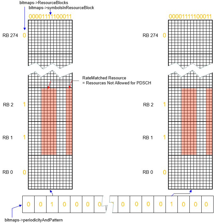
resourceBlocks runs down the side : a 275 bit string, one bit per resource block. RB 1 and RB 2 carry 1 in the drawing, while RB 0 and RB 274 carry 0, so only the marked blocks are blanked.symbolsInResourceBlock runs across the top : the 14 bit string reads 00001111100011, which marks symbols 4 to 8 and symbols 12 and 13. Those are the columns shaded red.periodicityAndPattern runs along the bottom : each bit is one slot, and the two bits set to 1 are the slots the pattern applies in. The arrows from those bits point up at the two grids.The three are ANDed, not added : a resource element is blanked only where a marked block, a marked symbol and a marked slot coincide. That is why the red area is a rectangle rather than whole rows or columns.Blanked means unavailable, not empty : the label in the middle reads RateMatched Resource = Resources Not Allowed for PDSCH. The PDSCH is rate matched around the area rather than punctured through it.
Choosing between the two arms of patternType
Drawing bitmaps is only one of the two ways to say where the region is. The patternType field is a CHOICE, and its other arm names a control resource set instead. The question worth asking before writing any bitmap is whether the area has already been described somewhere else.
A CORESET already carries its own frequency domain allocation and its own duration, because the UE needs both in order to decode PDCCH at all. Repeating that shape as a bitmap would store the same fact twice, and two copies of one fact can disagree after a reconfiguration touches only one of them. The controlResourceSet arm removes the second copy by pointing at the first.
The arms are alternatives, never a pair : a CHOICE carries exactly one of its members, so a single pattern is either bitmaps or controlResourceSet and cannot be both.Use controlResourceSet when the area is a CORESET : the shape is already configured, so pointing at it is shorter to encode and cannot drift out of step with the CORESET itself.Use bitmaps for anything else : a region that is not a control resource set has no other IE describing it, so the three bitmaps are the only way to state where it is.subcarrierSpacing follows from the arm in practice : it is marked Cond CellLevel, and a CORESET is defined inside a bandwidth part. A pattern written with the controlResourceSet arm therefore inherits the numerology rather than restating it.dummy has to be encoded and is not read : the field is mandatory in RateMatchPattern, so a sender must include it, and the name is how the specification says nothing depends on the value.
Where the configuration lives
A pattern can be defined in four different information elements, and that is more interesting than it first looks. Two of them apply to the whole serving cell and two apply inside one bandwidth part, and the switchable groups are not spread the same way.
The diagram below puts the four lists in the two columns they belong to, and shows what reaches across the gap between them. Read the top half as where patterns are defined, and the box at the bottom as the thing that names them afterwards.
Rate match patterns are defined at cell level or at BWP level, but the groups that DCI switches exist only in PDSCH-Config, and reach cell level patterns through the CHOICE.
Four information elements carry the list : ServingCellConfigCommon and ServingCellConfig at cell level, PDSCH-Config at BWP level, and PDSCH-ConfigBroadcast-r17 for broadcast PDSCH.Each list holds at most four patterns : the size bound is maxNrofRateMatchPatterns, which is 4, so the identifiers inside one list run 0 to 3.The groups exist in one place only : rateMatchPatternGroup1 and rateMatchPatternGroup2 appear in PDSCH-Config and nowhere else, so the switchable sets are configured per bandwidth part.A BWP level group can still name a cell level pattern : the CHOICE inside RateMatchPatternGroup has a cellLevel arm, which is how a per-BWP group reaches a pattern defined for the whole cell.That asymmetry is what the CHOICE is for : an identifier of 0 exists in both lists. A group entry therefore has to say which of the two it means.PDSCH-Config sits inside a bandwidth part : it is reached through pdsch-Config in BWP-DownlinkDedicated, so switching bandwidth part changes which patterns and which groups are in force.
What changes at which timescale
Two different clocks run through this configuration, and confusing them is the usual way to misread a log. Defining a pattern is an RRC action and happens rarely. Choosing whether a pattern applies right now is a scheduling action and happens in every downlink grant.
The diagram below separates the two. The band across the top is what RRC put in place and left alone, and the row underneath is four consecutive slots in which only the indicator differs.
The pattern list and the group membership are fixed by RRC. Only the rate matching indicator in each grant changes from one slot to the next.
Adding or reshaping a pattern needs a reconfiguration : the bitmaps and the group membership arrive in RRC, so neither can be changed inside the interval between two grants.Selecting a group needs nothing but the grant : the rate matching indicator carries one bit per group, so a scheduler enables either group, both or neither without any signalling of its own.The field is not always two bits wide : its width follows the number of groups configured, so it is 0, 1 or 2 bits. A cell with one group spends one bit, and a cell with none spends nothing.Fallback scheduling cannot switch anything : DCI format 1_0 has no rate matching indicator, so a transmission scheduled with it takes whatever applies without the groups.A pattern outside both groups is always on : group membership is what makes a pattern switchable, so a configured pattern that no group names applies to every transmission until RRC removes it.
Examples
Five worked configurations follow, and they are ordered so that each one adds a single idea to the one before it. The values in them are invented rather than captured, and every consequence stated underneath follows from the field definitions in the next section.
Example 01 > The configuration behind the drawing above
The picture at the top of this page shows three bitmaps without giving their values a name. This is the same pattern written out, so the drawing and the RRC can be read against each other.
Illustrative configuration,
{
    rateMatchPatternId 0,
    patternType bitmaps : {
        resourceBlocks '0110...0'B,                        -- 275 bits, RB 1 and RB 2 set
        symbolsInResourceBlock oneSlot : '00001111100011'B,
        periodicityAndPattern n20 : '00100000000100000000'B
    },
    subcarrierSpacing kHz30,
    dummy semiStatic
}
The symbol bitmap is the drawing’s : '00001111100011' marks symbols 4 to 8 and symbols 12 and 13, which is seven symbols and matches the shaded columns.Two resource blocks, not two hundred : only RB 1 and RB 2 carry a 1, so the pattern is narrow in frequency however wide the carrier is.The blanked count follows directly : 2 resource blocks x 12 subcarriers x 7 symbols is 168 resource elements in each slot the pattern applies to.periodicityAndPattern chooses the slots : n20 gives a 20 bit string, one bit per slot. The two bits set here put the pattern in slots 2 and 11 of every 20.subcarrierSpacing is conditional : the listing marks itCond CellLevel , so it is present for a cell level pattern and absent for a BWP level one.
Example 02 > Reserving a CORESET without drawing a bitmap
Not every blanked region has to be described by hand. When the area to avoid is a control resource set, the network already configured its frequency and duration once, and patternType has a second arm that simply points at it.
Illustrative configuration,
{
    rateMatchPatternId 1,
    patternType controlResourceSet : 1,
    dummy semiStatic
}
patternType is a CHOICE, and this is the other arm : bitmaps and controlResourceSet are alternatives, so a pattern uses one or the other and never both.No bitmaps means no bitmaps to keep in step : the CORESET already carries its own frequencyDomainResources and duration. Restating them would only create a way for the two to disagree.subcarrierSpacing is absent here : it is Cond CellLevel, and a CORESET is defined inside a bandwidth part, so the pattern inherits the numerology.Release 16 widened the identifier : controlResourceSet-r16 in the extension group carries ControlResourceSetId-r16, which reaches beyond the original identifier range.
Example 03 > The same identifier at two different levels
A pattern identifier on its own is ambiguous, and this example is why. The same list of patterns exists in two places, and an identifier of 0 means a different pattern depending on which of the two it was taken from.
Illustrative configuration,
ServingCellConfig {                          -- cell level
    rateMatchPatternToAddModList {
        { rateMatchPatternId 0, patternType bitmaps : { ... } }
    }
}

PDSCH-Config {                               -- BWP level
    rateMatchPatternToAddModList {
        { rateMatchPatternId 0, patternType controlResourceSet : 2 }
    }
}

rateMatchPatternGroup1 {
    cellLevel : 0,                           -- the first one
    bwpLevel : 0                             -- the second one
}
Both lists hold up to four patterns : RateMatchPatternId is INTEGER (0..maxNrofRateMatchPatterns-1) and maxNrofRateMatchPatterns is 4, so the identifiers run 0 to 3 in each list.That is why the group is a CHOICE : RateMatchPatternGroup is a SEQUENCE OF CHOICE between cellLevel and bwpLevel, because an identifier alone could not say which list it came from.Eight is four plus four : maxNrofRateMatchPatternsPerGroup is 8, which is exactly the two lists of four taken together.Cell level is configured in two places : rateMatchPatternToAddModList appears in ServingCellConfig and in ServingCellConfigCommon as well as in PDSCH-Config.
Example 04 > Two groups, switched per transmission
Everything so far is semi-static. The groups are what let a scheduler turn a blanked region on and off without a reconfiguration. The cost is two bits in the downlink grant, in a field called the rate matching indicator.
Illustrative configuration,
PDSCH-Config {
    rateMatchPatternGroup1 {
        cellLevel : 0,
        bwpLevel : 1
    },
    rateMatchPatternGroup2 {
        cellLevel : 2
    }
}

-- rate matching indicator in DCI format 1_1, MSB then LSB
--   00  neither group applies
--   01  group 2 only
--   10  group 1 only
--   11  both groups apply
The indicator is a bitmap : the MSB stands for rateMatchPatternGroup1 and the LSB for rateMatchPatternGroup2, so the four codepoints are the four combinations.The field can be narrower than two bits : the width follows the number of groups configured. A cell using one group spends one bit, and a cell using neither spends none.A group can hold more than one pattern : group 1 here carries two entries, and enabling the group enables both of them together.Four formats carry the field, and the fallback does not : format 1_1 reads the pair configured here, and format 1_2 reads its own pair. Format 1_3 reads rateMatchListDCI-1-3 for multi-cell scheduling, and format 4_2 reads the pair in pdsch-ConfigMulticast. Format 1_0 has no such field.DCI format 1_2 has its own pair : rateMatchPatternGroup1DCI-1-2-r16 and rateMatchPatternGroup2DCI-1-2-r16 were added in Release 16 so the two formats do not have to share.
Example 05 > An LTE carrier rather than a drawn region
The last example uses the other mechanism entirely. Nothing here draws a region, because the region is whatever an LTE carrier puts its cell specific reference signals on, and that shape is already fixed by LTE.
Illustrative configuration,
RateMatchPatternLTE-CRS {
    carrierFreqDL 500,
    carrierBandwidthDL n50,
    nrofCRS-Ports n4,
    v-Shift n0
    -- mbsfn-SubframeConfigList is OPTIONAL, Need M, and is omitted here
}
The fields describe a carrier, not a rectangle : a centre frequency, a bandwidth, a port count and a shift are enough, because the CRS positions follow from them.carrierBandwidthDL is counted in LTE resource blocks : the enumeration runs n6, n15, n25, n50, n75 and n100, which are the LTE channel bandwidths rather than NR ones.One carrier was the Release 15 limit : lte-CRS-ToMatchAround carries a single RateMatchPatternLTE-CRS, which is enough only while one LTE carrier overlaps.Release 16 made it a list : LTE-CRS-PatternList-r16 holds up to maxLTE-CRS-Patterns-r16, which is 3, and ServingCellConfig carries two such lists.
RRC Parameters
Four listings follow, and they nest. PDSCH-Config holds the list of patterns and the two groups that DCI can switch between. RateMatchPattern is one pattern, RateMatchPatternGroup is the switchable set, and RateMatchPatternLTE-CRS is the separate LTE mechanism.
Following is based on
PDSCH-Config ::= SEQUENCE { dataScramblingIdentityPDSCH INTEGER (0..1007) OPTIONAL, -- Need S dmrs-DownlinkForPDSCH-MappingTypeA SetupRelease { DMRS-DownlinkConfig } OPTIONAL, -- Need M dmrs-DownlinkForPDSCH-MappingTypeB SetupRelease { DMRS-DownlinkConfig } OPTIONAL, -- Need M tci-StatesToAddModList SEQUENCE (SIZE(1..maxNrofTCI-States)) OF TCI-State OPTIONAL, -- Need N tci-StatesToReleaseList SEQUENCE (SIZE(1..maxNrofTCI-States)) OF TCI-StateId OPTIONAL, -- Need N vrb-ToPRB-Interleaver ENUMERATED {n2, n4} OPTIONAL, -- Need S resourceAllocation ENUMERATED { resourceAllocationType0, resourceAllocationType1, dynamicSwitch}, pdsch-TimeDomainAllocationList SetupRelease { PDSCH-TimeDomainResourceAllocationList } OPTIONAL, -- Need M pdsch-AggregationFactor ENUMERATED { n2, n4, n8 } OPTIONAL, -- Need SrateMatchPatternToAddModList SEQUENCE (SIZE (1..maxNrofRateMatchPatterns)) OF RateMatchPattern OPTIONAL, -- Need N rateMatchPatternToReleaseList SEQUENCE (SIZE (1..maxNrofRateMatchPatterns)) OF RateMatchPatternId OPTIONAL, -- Need N rateMatchPatternGroup1 RateMatchPatternGroup OPTIONAL, -- Need R rateMatchPatternGroup2 RateMatchPatternGroup OPTIONAL, -- Need R rbg-Size ENUMERATED {config1, config2}, mcs-Table ENUMERATED {qam256, qam64LowSE} OPTIONAL, -- Need S maxNrofCodeWordsScheduledByDCI ENUMERATED {n1, n2} OPTIONAL, -- Need R prb-BundlingType CHOICE { static SEQUENCE { bundleSize ENUMERATED { n4, wideband } OPTIONAL -- Need S }, dynamic SEQUENCE { bundleSizeSet1 ENUMERATED { n4, wideband, n2-wideband, n4-wideband } OPTIONAL, -- Need S bundleSizeSet2 ENUMERATED { n4, wideband } OPTIONAL -- Need S } }, ..., [[ -- Release 16, the DCI format 1_2 counterparts of the two groups above ...rateMatchPatternGroup1DCI-1-2-r16 RateMatchPatternGroup OPTIONAL, -- Need R rateMatchPatternGroup2DCI-1-2-r16 RateMatchPatternGroup OPTIONAL, -- Need R ... ]], ... }
Following is based on
RateMatchPatternGroup ::=               SEQUENCE (SIZE (1..maxNrofRateMatchPatternsPerGroup)) OF CHOICE {
    cellLevel                               RateMatchPatternId,
    bwpLevel                                RateMatchPatternId
}
Following is based on
RateMatchPattern ::= SEQUENCE { rateMatchPatternId RateMatchPatternId, patternType CHOICE {bitmaps SEQUENCE { resourceBlocks BIT STRING (SIZE (275)), symbolsInResourceBlock CHOICE { oneSlot BIT STRING (SIZE (14)), twoSlots BIT STRING (SIZE (28)) }, periodicityAndPattern CHOICE { n2 BIT STRING (SIZE (2)), n4 BIT STRING (SIZE (4)), n5 BIT STRING (SIZE (5)), n8 BIT STRING (SIZE (8)), n10 BIT STRING (SIZE (10)), n20 BIT STRING (SIZE (20)), n40 BIT STRING (SIZE (40)) } OPTIONAL, -- Need S ... }, controlResourceSet ControlResourceSetId }, subcarrierSpacing SubcarrierSpacing OPTIONAL, -- Cond CellLevel dummy ENUMERATED { dynamic, semiStatic }, ..., [[ controlResourceSet-r16 ControlResourceSetId-r16 OPTIONAL -- Need R ]] }
Following is based on
RateMatchPatternLTE-CRS ::=         SEQUENCE {
    carrierFreqDL                       INTEGER (0..16383),
    carrierBandwidthDL                  ENUMERATED {n6, n15, n25, n50, n75, n100, spare2, spare1},
    mbsfn-SubframeConfigList            EUTRA-MBSFN-SubframeConfigList                                          OPTIONAL,   -- Need M
    nrofCRS-Ports                       ENUMERATED {n1, n2, n4},
    v-Shift                             ENUMERATED {n0, n1, n2, n3, n4, n5}
}

LTE-CRS-PatternList-r16 ::=         SEQUENCE (SIZE (1..maxLTE-CRS-Patterns-r16)) OF RateMatchPatternLTE-CRS
What was added after Release 15
The RateMatchPattern side of this page has barely moved. One field arrived in Release 16, controlResourceSet-r16, and the rest of that IE reads as Release 15 wrote it. The LTE CRS side is where the work went, and dynamic spectrum sharing is the reason.
Release 15 let a cell name one LTE carrier to rate match around. That is enough while one NR carrier overlaps one LTE carrier, and it stops being enough as soon as the overlap involves more than one. The later releases replace the single pattern with lists.
Field |
IE it sits in |
What it adds |
|---|---|---|
lte-CRS-ToMatchAround |
ServingCellConfig, ServingCellConfigCommon |
The Release 15 form. One RateMatchPatternLTE-CRS, so one LTE carrier to avoid. |
lte-CRS-PatternList1-r16, lte-CRS-PatternList2-r16 |
ServingCellConfig |
Each is a SetupRelease of LTE-CRS-PatternList-r16, which is itself a list of patterns, so several LTE carriers can be avoided at once. |
lte-CRS-PatternList3-r18, lte-CRS-PatternList4-r18 |
ServingCellConfig |
Two further lists, added in Release 18. |
crs-RateMatch-PerCORESETPoolIndex-r16 |
ServingCellConfig |
Lets the CRS rate matching differ per CORESET pool, which matters when two transmission points serve one UE. |
lte-CRS-ToMatchAround-r17 |
PDSCH-ConfigBroadcast-r17 |
Carries the same pattern for broadcast PDSCH, which had no way to state it before. |
A second addition belongs to the group side rather than the pattern side. Release 16 gave DCI format 1_2 its own pair, rateMatchPatternGroup1DCI-1-2-r16 and rateMatchPatternGroup2DCI-1-2-r16, so it no longer shares the groups DCI format 1_1 uses. Both appear in the PDSCH-Config listing above.
The DCI field that reads those groups is a bitmap rather than a selector, and it is 0, 1 or 2 bits wide depending on how many groups are configured. The MSB indicates rateMatchPatternGroup1 and the LSB indicates rateMatchPatternGroup2. One bit per group is what lets a scheduler enable either, both or neither, per transmission.
The pattern IE is essentially unchanged : only controlResourceSet-r16 was added to RateMatchPattern, so a Release 15 reading of the bitmaps still holds.One LTE carrier became several : lte-CRS-PatternList1-r16 and lte-CRS-PatternList2-r16 replace a single pattern with lists, and Release 18 adds a third and fourth.Broadcast PDSCH caught up in Release 17 : lte-CRS-ToMatchAround-r17 in PDSCH-ConfigBroadcast-r17 lets broadcast transmissions avoid LTE CRS as unicast already could.The indicator is a bitmap : the MSB selects group 1 and the LSB selects group 2. The field is 0, 1 or 2 bits wide depending on how many groups exist.Release 18 extends it across cells : rateMatchListDCI-1-3-r18 in MC-DCI-SetOfCells-r18 carries a rate matching indicator index per scheduled cell, for the multi-cell DCI format 1_3.
Reference