|
5G/NR - Pre Trial - Frame Structure |
|||||||||||||||||||||||||||||||
|
NOTE : This note is about a tempary 5G specification that was implemented and tried before 5G specification is finalized. I keep this note for study purpose.
Frame Structure
As mentioned in Overview page, one of the critical differences in terms of waveform design between 5G Pretrial and current LTE is that in 5G Pre Trial the subcarrier spacing is 75 Khz as opposed to 15 Khz in current LTE. It means Subcarrier spacing of the Pre-Trial is 5 times wider than LTE subcarrier spacing. As a result, the OFDM symbol length of 5G Pre Trial gets 5 times shorter than LTE symbol length. This in turn gives result that the length of one subframe in Pretrial spec gets 5 times shorter than LTE subframe length. However, 5G Pretrial set the length of one Radio Frame to be same as in LTE. It means that in 5G Radio Frame are 5 times more subframes than LTE radio frame.
Confusing ??? I know it is confusing :). Let me put these in tabular format.
Followings are the items that will be briefly described in this page. I will create separate pages for each of the Physical channels for the details, but you would have bird's eye view over overal frames in single page here.
Both trial specification defines four different subframe structure (type) as follows. Following illustration shows the possible structure of one subframe (0.2 ms) and each label stands for :
a. Subframe including DL control channel and DL data channel
b. Subframe including DL control channel, DL data channel and UL control channel
c. Subframe including DL control channel and UL data channel
d. Subframe including DL control channel, UL data channel and UL control channel.
Radio Frame Structure - Downlink
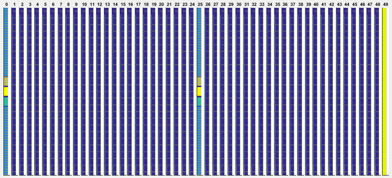
As mentioned above, in Pre trial specification one radio frame consists of 50 subframes. One example of the radio frame is shown below. Subframe 0 and 25 are a kind of special subframe which carries synchronization signals (PSS, SSS, ESS) and Beam Forming Reference signal (BSR). The contents in all other subframes varies depending on subframe type and scheduling information.
Matlab Code : TestFrame
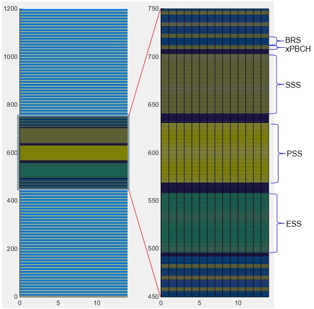
As mentioned above, subframe 0 and 25 is special ones that carries various synchronization signal,reference signal and xPBCH. If I magnify the subframe 0, 25, it would look as follows.
< Structure of Subframe 0 and 25 >
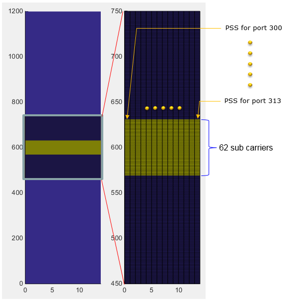
PSS (Primary Synchronization Signal)
The purpose of Primary synchronization Signal is same as PSS in LTE. That is, it is used for Radio Frame Synchronization. It is defined in 211-6.8.1 Primary synchronization signal (PSS). It is made up of 62 data based on Zadoff-Chu sequence and occupy 62 subcarriers, but in resource allocation total 72 sub carrier (6 RB) is allocated for the PSS. It means 5 sub carriers on both side of PSS is reserved (not used) as a kind of gap. One big difference you see in comparision to current LTE would be that in 5G Pretrial the PSS is transmitted in all OFDM symbols whereas PSS is transmitted in only one OFDM symbol in LTE. This is because Network in PreTrial is transmitting PSS for 14 different antenna ports as indicated below.
Matlab Code : PSS
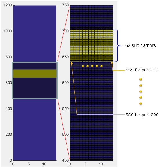
SSS (Secondary Synchronization Signal)
The purpose of Primary synchronization Signal is same as PSS in LTE. That is, it is used for Radio Frame Synchronization. It is defined in 211-6.8.2 Secondary synchronization signal (SSS). It is made up of 62 data based on Gold Sequence and occupy 62 subcarriers, but in resource allocation total 72 sub carrier (6 RB) is allocated for the PSS. It means 5 sub carriers on both side of PSS is reserved (not used) as a kind of gap. One big difference you see in comparision to current LTE would be that in 5G Pretrial the SSS is transmitted in all OFDM symbols whereas SSS is transmitted in only one OFDM symbol in LTE. This is because Network in PreTrial is transmitting SSS for 14 different antenna ports as indicated below.
Matlab Code : SSS
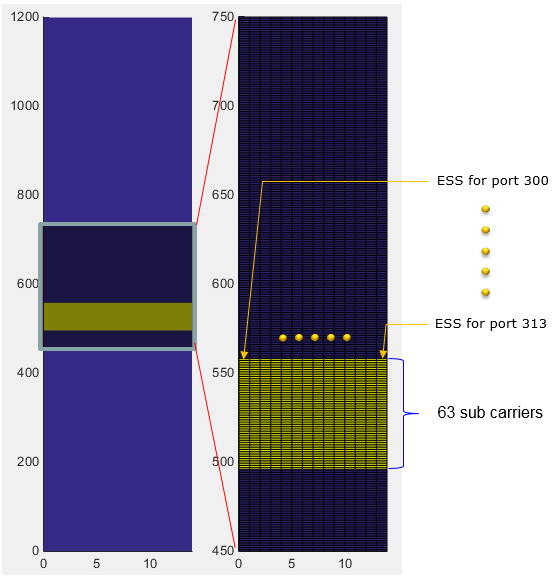
ESS (Extended Synchronization Signal)
ESS is a new type of Synchronization signal that is not in current LTE. The purpose of Extended synchronization Signal is to identify the OFDM symbol index and transmitted in symbol 0-13 in subframes 0 and 25. It is defined in 211-6.8.3 Extended synchronization signal. It is made up of 62 data based on Zadoff-Chu sequence and occupy 62 subcarriers, but in resource allocation total 72 sub carrier (6 RB) is allocated for the ESS. It means 5 sub carriers on both side of ESS is reserved (not used) as a kind of gap. The ESS is transmitted in all OFDM symbols. This is because Network in PreTrial is transmitting ESS for 14 different antenna ports as indicated below.
Matlab Code : ESS
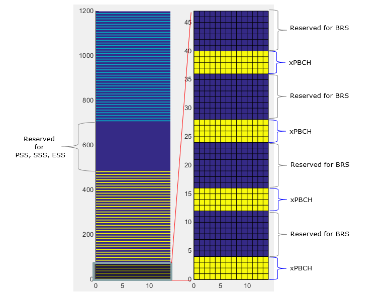
xPBCH is broadcasted in subframe 0 and 25 and it carries broadcasting message (MIB) at each and every OFDM symbols using the same beams used for beam reference signals in each OFDM symbol.
Matlab Code : xPBCH
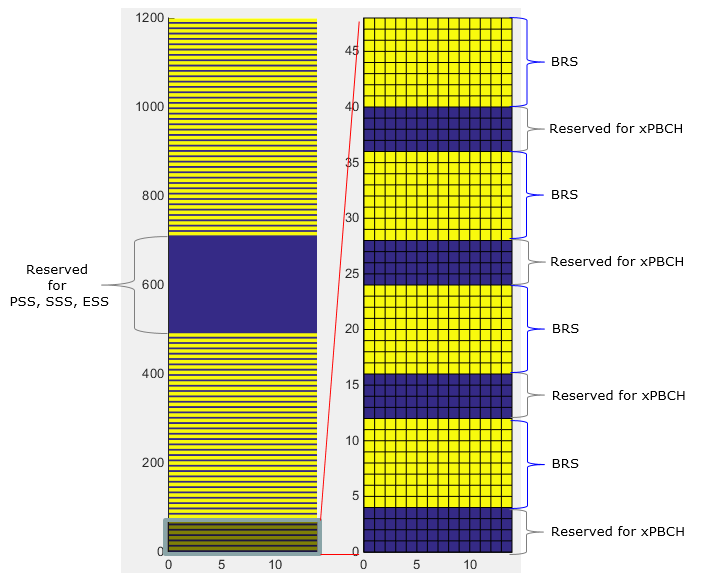
BRS is a special reference signal to let UE knows of the identification of each Beam that the network transmit. It also functions as DMRS for xPBCH. It occupies 8 subcarriers(5th~12th subcarrier) in every RB(resrouce bloc) except the 18 RBs at the center of the frequency (Note : The 18 RBs at the center is reserved for PSS, SSS, ESS). It is transmitted at every symbols (i.e, symbol 0 ~ 13) in subframe 0 and 25 as shown below. The data is based on Pseudo Random Data (Gold Sequence).
Matlab Code : BRS
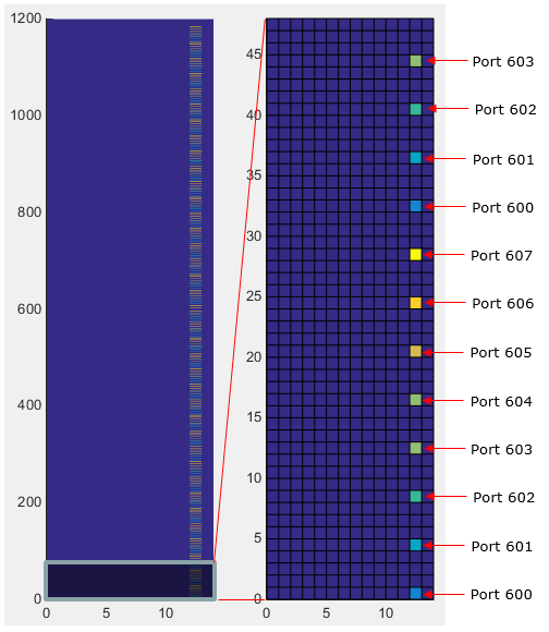
BRRS (Beam Refinement Reference Signal)
BRRS is the signal transmitted by gNB for Beam Refinement and the subframe and the symbols for BRRS is configured by DCI. The location of BRRS in frequency domain varies depending on antenna port as shown below.
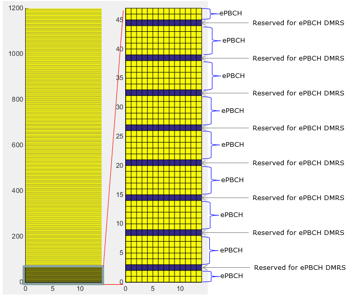
ePBCH is the channel that carries SIB (xSystemInformation). It can be transmitted in a specified SFN and a specified subframe depending on the configuration specified in MIB. In the subframe assigned for ePBCH, it is transmitted in all symbols (symbol 0~13) and transmitted across the whole bandwidth (i.e, in all RBs). It occupies 10 subcarriers in each RB (all the subcarrier except 3rd and 9th subcarriers).
< ePBCH >
Matlab Code : ePBCH
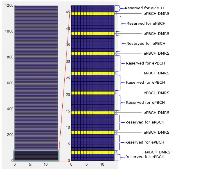
< DMRS for ePBCH >
Matlab Code : ePBCH DMRS
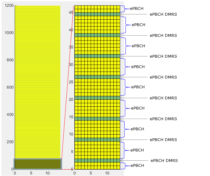
< ePBCH and DMRS >
Matlab Code : ePBCH and DMRS
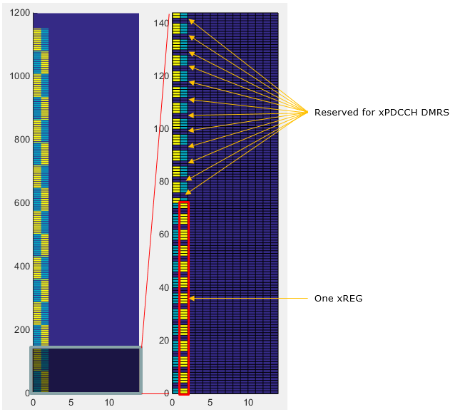
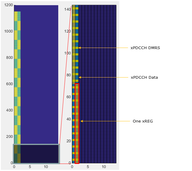
xREG is not a specific physical channel. It is a term indicating a specific locations in control channel area. It is similar to CCE in LTE, but xREG allocation rule is much simpler than LTE CCE. There are 16 xREG within one OFDM symbol (Note : Depending on configuration, we can use only one OFDM symbol or two OFDM symbols for control region). Within one xREG, there are multiple groups of Resource Elements for carrying control channel data (DCI) and multiple groups of Resource Elements allocated to carry DMRS signal as illustrated below.
NOTE : This example shows the case where two OFDM symbols are allocated for downlink control region. But there can be cases where only one OFDM symbol is allocated for downlink control region.
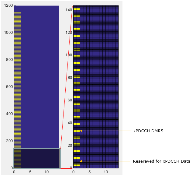
xPDCCH is the physical channel that carries DCI data and xPDCCH DMRS is the reference signal that helps UE to decode xPDCCH. The location of these data is allocated to a specific xREG which is explained in previous section.
NOTE : This example shows the case where two OFDM symbols are allocated for downlink control region. But there can be cases where only one OFDM symbol is allocated for downlink control region.
< Location (Resource Elements) for xPDCCH DMRS >
< Location (Resource Elements) for xPDCCH and DMRS >
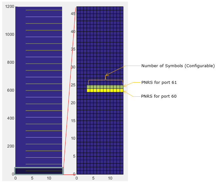
xPDSCH PNRS(Phase noise reference signal)
|
|||||||||||||||||||||||||||||||