The topics I will describe in this page is higher level measurement(i.e, RRC layer measurement), but this higher layer measurement is based on very complicated lower layer process. It means you need to do a lot of study on lower layer process to fully understand the details of this higher layer process and parameters that will be explained in this page. For the lower layer process related to measurement report, refer to following pages. You would need to go back and forth many times between this page and following pages.
- Low Layer Measurement
- Rrc Measurement
- Overall Structure of Measurement Item and Configuration
- Measurement Event
- Measurement GAP
- Measurement of NR Cell
- Conformance Test
Overall Structure of Measurement Item and Configuration
Measurement process is configured by a very complicated (probably the most complicated RRC configuration) and confusing RRC parameters. I would suggest you to make practice of understanding some big picture of the overall structure before digging into each individual element.
The first step for the measurement process is to determine "what to measure ?". For every measurement process, the physical entities to measure is some kind of reference signal. In LTE, those reference signal for the measurement are synchronization signal and/or CRS(Cell Specific Reference signal). Those reference signals in LTE is structured relatively simple way, so the configuration in RRC message is relatively simple. In NR, the types of reference signal is synchronization signal/PBCH Reference Signal and CSI-RS (As you know, in NR there is no Cell Specific Reference signal. Instead, we use special type of reference signal called CSI-RS).
CSI-Based Measurement Configuration
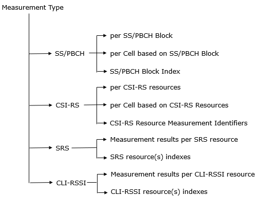
With types of reference signal for the measurements, the measurement types in NR can be catetorized as follows (this is based on 38.331-5.5.1)
RRC Based Measurement Configuration
Once the measurement item (target reference signal to measure), we have to determine the purpose of the measurement and various other details. Then finally you have to configure all of the details into RRC message. The overall structure of RRC message structure for the measurement can be summarized as follows (this is based on 38.331-5.5.1)
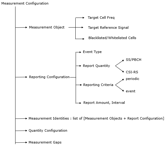
Followings are description of each catetories of the configurations :
-
Measurement objects Configuration : These are the entities on which the UE performs measurements. They vary by the type of measurement, such as intra-frequency, inter-frequency, and inter-RAT (Radio Access Technology), and include details like frequency/time location, cell-specific offsets, and lists of blacklisted/whitelisted cells. The object ID links the measurement object to each serving cell. Reporting configurations : These define how the UE reports measurements and include the triggering criteria, the reference signal (RS) type used for measurements, and the reporting format. Conditional reconfiguration includes additional criteria and RS types for execution.Measurement Configuration : These are lists linking measurement objects to reporting configurations. Multiple measurement identities can link to one reporting configuration, and the measurement identity is included in the report sent to the network.Quantity configurations : These configurations determine the filtering applied to measurements during event evaluation, reporting, and periodic reporting. They can have different filter coefficients for various measurement quantities and RS types.Measurement gaps Configuration : These are the time periods that the UE can utilize to perform the specified measurements.
I think you can easily understand the function/role of each components by themselves, but you would easily get lost when you look into the RRC messages from real application (e.g, field log). The confusion would come from the lack of understanding of inter-relashionships among these component. My personal approach to work around these confusions is to use data base concept (relational database in this case). Let's put aside Qunatity Configuration and Measurement Gap for now and apply database
analogy to Measurement Objects Configuration, Reporting Configuration and Measurement Configuration. Basic idea is to describe these components as a data table in a relational database as follows (
- Measurement Objects Table:
- meas_object_id (Primary Key): Unique identifier for each measurement object.
- object_type: Type of object (e.g., intra-frequency, inter-frequency, inter-RAT).
- frequency: Frequency of the measured object.
- cell_id: ID of the cell to be measured (if applicable).
- ...other attributes: (e.g., offsets, blacklisted/whitelisted cells).
- Reporting Configurations Table:
- report_config_id (Primary Key): Unique identifier for each reporting configuration.
- reporting_criteria: Conditions triggering a report (e.g., threshold, periodic).
- report_format: Structure of the report.
- rs_type: Reference signal used for measurement.
- ...other attributes: (e.g., hysteresis, time-to-trigger).
- Measurement Identities Table:
- meas_id (Primary Key): Unique identifier for each measurement identity.
- meas_object_id (Foreign Key): Links to the Measurement Objects table.
- report_config_id (Foreign Key): Links to the Reporting Configurations table.
- One-to-many between Reporting Configurations and Measurement Identities: One reporting configuration can be associated with multiple measurement identities, allowing different objects to be reported under the same rules.
- One-to-many between Measurement Objects and Measurement Identities: One measurement object can be linked to multiple measurement identities, enabling different reporting configurations for the same object under different conditions.
Measurement Object Table
|
meas_object_id |
object_type |
frequency |
cell_id |
|---|---|---|---|
|
1 |
intra-frequency |
2600 MHz |
Cell A |
|
2 |
intra-frequency |
2600 MHz |
Cell B |
Reporting Configuration Table
|
report_config_id |
reporting_criteria |
report_format |
|---|---|---|
|
1 |
periodic, frequent |
RSRP, RSRQ |
|
2 |
periodic, infrequent |
RSRP |
Measurement Configuration Table
|
meas_id |
meas_object_id |
report_config_id |
|---|---|---|
|
1 |
1 |
1 |
|
2 |
2 |
2 |
Measurment Event
Following table is based on ReportConfigNR in 38.331
|
Event Type |
Description |
|
Event A1 |
Serving becomes better than threshold |
|
Event A2 |
Serving becomes worse than threshold |
|
Event A3 |
Neighbour becomes amount of offset better than PCell/PSCell |
|
Event A4 |
Neighbour becomes better than threshold |
|
Event A5 |
PCell/PSCell becomes worse than absolute threshold1 AND Neighbour/SCell becomes better than another absolute threshold2 |
|
Event A6 |
Neighbour becomes amount of offset better than SCell |
|
CondEvent A3 |
Conditional reconfiguration candidate becomes amount of offset better than PCell/PSCell |
|
CondEvent A5 |
PCell/PSCell becomes worse than absolute threshold1 AND Conditional reconfiguration candidate becomes better than another absolute threshold2 |
|
Event B1 |
Inter RAT neighbour becomes better than threshold |
|
Event B2 |
PCell becomes worse than threshold1 and inter RAT neighbour becomes better than threshold2 |
|
Event C1 |
The NR sidelink channel busy ratio is above a threshold |
|
Event C2 |
The NR sidelink channel busy ratio is below a threshold |
|
Event D1 |
Distance between UE and referenceLocation1 is above threshold1 and distance between UE and referenceLocation2 is below threshold2 |
|
Event I1 |
Interference becomes higher than absolute threshold |
|
Event X1 |
Serving L2 U2N Relay UE becomes worse than threshold1 and NR Cell becomes better than threshold2 |
|
Event X2 |
Serving L2 U2N Relay UE becomes worse than threshold |
|
Event Y1 |
PCell becomes worse than threshold1 and candidate L2 U2N Relay UE becomes better than threshold2 |
|
Event Y2 |
Candidate L2 U2N Relay UE becomes better than threshold |
Measurement GAP
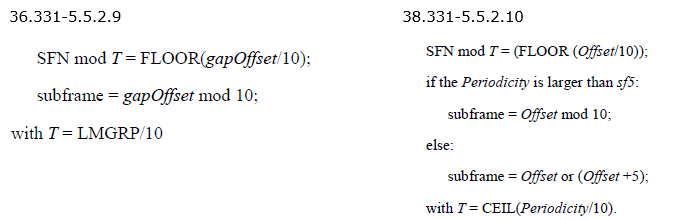
Fundamental logic of the GAP setting is same as in LTE and Legacy case as explained above. Recap the procedure, it can be summarized as follows.
i) Get the Gap Pattern ID from RRC MeasGapConfig and additional SMTC parameter from
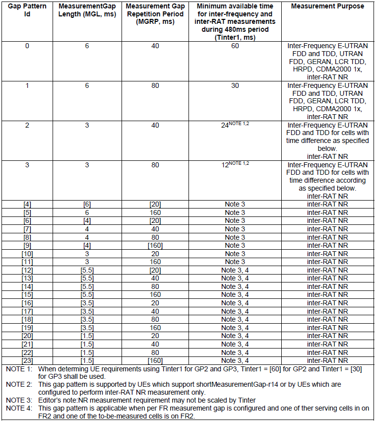
ii) Get the detailed Gap Setting Parameters for the Gap Pattern from 36.133 Table 8.1.2.1-1
iii) Determine Gap Subframe based on the condition described as below
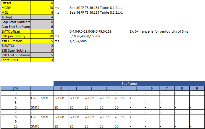
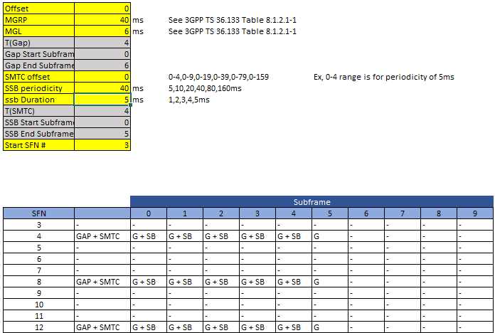
Rules may sound simple ? It may sound simple, but you would not know how complicated it is before you really try it. Rehan has put a lot of his time and effort on this and completed the excel spreadsheet to show the gap settings for each subframe automatically according to the parameters you set. He kindly allowed me to share the spreadsheet for readers. Click here to get the file.
Followings a few examples from the spreadsheet.
NOTE : You only need to set parameters highlighted in yellow. The values for grey cells are automatically derived from the vlues in yellow cells.
Example 1 > MGRP = 40ms, SSB Periodicity = 20ms
Example 2 > MGRP = 40ms, SSB Periodicity = 40ms
Basically overall RRC Structure is similar to LTE/Legacy case explained above, but there are a couple of additiona flags a shown and a lot of different gapoffset as shown below.
From 36.331
MeasConfig ::= SEQUENCE {
....
measGapConfig MeasGapConfig OPTIONAL,
...
[[
measGapConfigPerCC-List-r14 MeasGapConfigPerCC-List-r14 OPTIONAL,
measGapSharingConfig-r14 MeasGapSharingConfig-r14 OPTIONAL
]],
[[
fr1-Gap-r15 BOOLEAN OPTIONAL, -- Need ON
mgta-r15 BOOLEAN OPTIONAL -- Need ON
]],
[[
measGapConfigDensePRS-r15 MeasGapConfigDensePRS-r15 OPTIONAL,
heightThreshRef-r15 CHOICE {
release NULL,
setup INTEGER (0..31)
} OPTIONAL --Need ON
]]
}
MeasGapConfig ::= CHOICE {
release NULL,
setup SEQUENCE {
gapOffset CHOICE {
gp0 INTEGER (0..39),
gp1 INTEGER (0..79),
...,
gp2-r14 INTEGER (0..39),
gp3-r14 INTEGER (0..79),
gp-ncsg0-r14 INTEGER (0..39),
gp-ncsg1-r14 INTEGER (0..79),
gp-ncsg2-r14 INTEGER (0..39),
gp-ncsg3-r14 INTEGER (0..79),
gp-nonUniform1-r14 INTEGER (0..1279),
gp-nonUniform2-r14 INTEGER (0..2559),
gp-nonUniform3-r14 INTEGER (0..5119),
gp-nonUniform4-r14 INTEGER (0..10239),
gp4-r15 INTEGER (0..19),
gp5-r15 INTEGER (0..159),
gp6-r15 INTEGER (0..19),
gp7-r15 INTEGER (0..39),
gp8-r15 INTEGER (0..79),
gp9-r15 INTEGER (0..159),
gp10-r15 INTEGER (0..19),
gp11-r15 INTEGER (0..159)
}
}
}
From 38.331
MeasObjectNR ::= SEQUENCE {
}
SSB-MTC ::= SEQUENCE {
periodicityAndOffset CHOICE {
sf5 INTEGER (0..4),
sf10 INTEGER (0..9),
sf20 INTEGER (0..19),
sf40 INTEGER (0..39),
sf80 INTEGER (0..79),
sf160 INTEGER (0..159)
},
duration ENUMERATED { sf1, sf2, sf3, sf4, sf5 }
}
SSB-MTC2 ::= SEQUENCE {
pci-List SEQUENCE (SIZE (1..maxNrofPCIsPerSMTC)) OF PhysCellId OPTIONAL,
periodicity ENUMERATED {sf5, sf10, sf20, sf40, sf80, spare3, spare2, spare1}
}
< 36.133 v15.3 - Table 8.1.2.1-1: Gap Pattern Configurations supported by the UE >
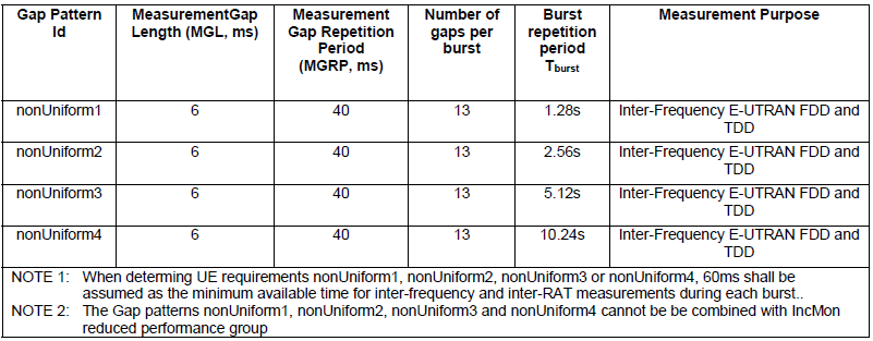
< 36.133 v15.3 - Table 8.1.2.1-2: Gap Pattern Configurations for UE supporting low density burst gap pattens >
Measurement of NR Cell
The purpose of this section is to provide you with various examples of measurement configurations in RRC messages. I would suggest you to try to get big picture (overall structure) of the RRC message based on tree diagram shown in previous section.
Example 01 >
This is an example RRC message for LTE measurement for LTE and NR cell from Amarisoft.
{
"rrcConnectionReconfiguration": {
"rrc-TransactionIdentifier": 0,
"criticalExtensions": {
"c1": {
"rrcConnectionReconfiguration-r8": {
"measConfig": {
"measObjectToAddModList": [
{
"measObjectId": 1,
"measObject": {
"measObjectEUTRA": {
"carrierFreq": 300,
"allowedMeasBandwidth": "mbw100",
"presenceAntennaPort1": true,
"neighCellConfig": "'01'B"
}
}
},
{
"measObjectId": 2,
"measObject": {
"measObjectNR-r15": {
"carrierFreq-r15": 631968,
"rs-ConfigSSB-r15": {
"measTimingConfig-r15": {
"periodicityAndOffset-r15": {
"sf20-r15": 0
},
"ssb-Duration-r15": "sf1"
},
"subcarrierSpacingSSB-r15": "kHz30"
},
"quantityConfigSet-r15": 1,
"bandNR-r15": {
"setup": 78
}
}
}
}
],
"reportConfigToAddModList": [
{
"reportConfigId": 1,
"reportConfig": {
"reportConfigEUTRA": {
"triggerType": {
"event": {
"eventId": {
"eventA1": {
"a1-Threshold": {
"threshold-RSRP": 90
}
}
},
"hysteresis": 10,
"timeToTrigger": "ms320"
}
},
"triggerQuantity": "rsrp",
"reportQuantity": "both",
"maxReportCells": 1,
"reportInterval": "ms120",
"reportAmount": "r1"
}
}
},
{
"reportConfigId": 2,
"reportConfig": {
"reportConfigEUTRA": {
"triggerType": {
"event": {
"eventId": {
"eventA2": {
"a2-Threshold": {
"threshold-RSRP": 60
}
}
},
"hysteresis": 0,
"timeToTrigger": "ms640"
}
},
"triggerQuantity": "rsrp",
"reportQuantity": "both",
"maxReportCells": 1,
"reportInterval": "ms120",
"reportAmount": "r1"
}
}
},
{
"reportConfigId": 3,
"reportConfig": {
"reportConfigInterRAT": {
"triggerType": {
"event": {
"eventB1-NR-r15": {
"b1-ThresholdNR-r15": {
"nr-RSRP-r15": 76
},
"reportOnLeave-r15": false
}
},
"hysteresis": 0,
"timeToTrigger": "ms100"
},
"maxReportCells": 8,
"reportInterval": "ms120",
"reportAmount": "r1",
"reportQuantityCellNR-r15": {
"ss-rsrp": true,
"ss-rsrq": true,
"ss-sinr": true
}
}
}
}
],
"measIdToAddModList": [
{
"measId": 2,
"measObjectId": 1,
"reportConfigId": 2
},
{
"measId": 3,
"measObjectId": 2,
"reportConfigId": 3
}
],
"quantityConfig": {
"quantityConfigEUTRA": {
"filterCoefficientRSRP": "fc3"
},
"quantityConfigNRList-r15": [
{
"measQuantityCellNR-r15": {
"filterCoeff-RSRP-r15": "fc3"
}
}
]
},
"measGapConfig": {
"release": null
}
}
}
}
}
}
}
It is always good practice (I strongly suggest) to summarize the configuration in a table as below.
Measurement Object Table
|
Measurement Object ID |
carrierFreq |
allowedMeasBandwidth |
carrierFreq-r15 |
bandNR-r15 |
|---|---|---|---|---|
|
1 |
300 |
mbw100 |
||
|
2 |
631968 |
setup: 78 |
Report ConfigurationTable
|
Reporting Configuration ID |
trigger Type |
trigger Quantity |
report Quantity |
max ReportCells |
report Interval |
report Amount |
reportQuantity CellNR-r15 |
|---|---|---|---|---|---|---|---|
|
1 |
eventA1 |
rsrp |
both |
1 |
ms120 |
r1 |
|
|
2 |
eventA2 |
rsrp |
both |
1 |
ms120 |
r1 |
|
|
3 |
[eventB1-NR-r15] |
8 |
ms120 |
r1 |
{'ss-rsrp': True, 'ss-rsrq': True, 'ss-sinr': True} |
Measurement Configuration Table
|
MeasurementId |
measObjectId |
reportConfigId |
|---|---|---|
|
2 |
1 |
2 |
|
3 |
2 |
3 |
Example 02 >
This is an example RRC message for LTE measurement for LTE and NR cell from Amarisoft.
RrcReconfiguration for Scell Measurement
{
message c1: rrcReconfiguration: {
rrc-TransactionIdentifier 0,
criticalExtensions rrcReconfiguration: {
measConfig {
measObjectToAddModList {
{
measObjectId 1,
measObject measObjectNR: {
ssbFrequency 621216,
ssbSubcarrierSpacing kHz30,
smtc1 {
periodicityAndOffset sf20: 0,
duration sf1
},
referenceSignalConfig {
ssb-ConfigMobility {
deriveSSB-IndexFromCell FALSE
}
},
quantityConfigIndex 1,
offsetMO {
},
freqBandIndicatorNR 78
}
},
{
measObjectId 2,
measObject measObjectNR: {
ssbFrequency 627264,
ssbSubcarrierSpacing kHz30,
smtc1 {
periodicityAndOffset sf20: 0,
duration sf1
},
referenceSignalConfig {
ssb-ConfigMobility {
deriveSSB-IndexFromCell FALSE
}
},
quantityConfigIndex 1,
offsetMO {
},
freqBandIndicatorNR 78
}
}
},
reportConfigToAddModList {
{
reportConfigId 1,
reportConfig reportConfigNR: {
reportType eventTriggered: {
eventId eventA2: {
a2-Threshold rsrp: 16,
reportOnLeave FALSE,
hysteresis 0,
timeToTrigger ms0
},
rsType ssb,
reportInterval ms120,
reportAmount r1,
reportQuantityCell {
rsrp TRUE,
rsrq TRUE,
sinr TRUE
},
maxReportCells 1,
includeBeamMeasurements FALSE
}
}
},
{
reportConfigId 2,
reportConfig reportConfigNR: {
reportType eventTriggered: {
eventId eventA4: {
a4-Threshold rsrp: 36,
reportOnLeave FALSE,
hysteresis 0,
timeToTrigger ms0,
useWhiteCellList FALSE
},
rsType ssb,
reportInterval ms120,
reportAmount r1,
reportQuantityCell {
rsrp TRUE,
rsrq TRUE,
sinr TRUE
},
maxReportCells 1,
includeBeamMeasurements FALSE
}
}
}
},
measIdToAddModList {
{
measId 1,
measObjectId 2,
reportConfigId 2
}
},
quantityConfig {
quantityConfigNR-List {
{
quantityConfigCell {
ssb-FilterConfig {
},
csi-RS-FilterConfig {
}
}
}
}
},
measGapConfig {
gapUE setup: {
gapOffset 16,
mgl ms6,
mgrp ms40,
mgta ms0
}
}
},
nonCriticalExtension {
masterCellGroup {
cellGroupId 0,
spCellConfig {
spCellConfigDedicated {
initialDownlinkBWP {
pdsch-Config setup: {
resourceAllocation resourceAllocationType1,
rbg-Size config1,
mcs-Table qam256,
prb-BundlingType staticBundling: {
bundleSize wideband
}
}
},
uplinkConfig {
initialUplinkBWP {
pusch-Config setup: {
txConfig codebook,
resourceAllocation resourceAllocationType1,
mcs-Table qam256,
mcs-TableTransformPrecoder qam256,
codebookSubset nonCoherent,
maxRank 1
}
}
},
tag-Id 0
}
}
},
dedicatedNAS-MessageList {
'7E022CCB5D1C017E0042010977000B...'H
}
}
}
}
}
It is always good practice (I strongly suggest) to summarize the configuration in a table as below.
Measurement Objects Table
|
Measurement Object ID |
ssbFrequency |
ssb Subcarrier Spacing |
smtc1 (periodicityAndOffset, duration) |
referenceSignalConfig (deriveSSB-IndexFromCell) |
quantity ConfigIndex |
freqBand IndicatorNR |
|---|---|---|---|---|---|---|
|
1 |
621216 |
kHz30 |
sf20: 0, sf1 |
FALSE |
1 |
78 |
|
2 |
627264 |
kHz30 |
sf20: 0, sf1 |
FALSE |
1 |
78 |
Reporting Configurations Table
|
Reporting Configuration ID |
report Type |
eventId |
a2-Threshold/ a4-Threshold (rsrp) |
report On Leave |
time To Trigger |
rsType |
report Interval |
report Amount |
report Quantity Cell (rsrp, rsrq, sinr) |
max Report Cells |
include Beam Measurements |
|---|---|---|---|---|---|---|---|---|---|---|---|
|
1 |
event Triggered |
eventA2 |
16 |
FALSE |
ms0 |
ssb |
ms120 |
r1 |
TRUE, TRUE, TRUE |
1 |
FALSE |
|
2 |
event Triggered |
eventA4 |
36 |
FALSE |
ms0 |
ssb |
ms120 |
r1 |
TRUE, TRUE, TRUE |
1 |
FALSE |
Measurement Identities Table
|
MeasurementId |
measObjectId |
reportConfigId |
|---|---|---|
|
1 |
2 |
2 |
Following is an example of measurement report based on the configuration above
Measurement Report
{
message c1: measurementReport: {
criticalExtensions measurementReport: {
measResults {
measId 1,
measResultServingMOList {
{
servCellId 0,
measResultServingCell {
physCellId 500,
measResult {
cellResults {
resultsSSB-Cell {
rsrp 70,
rsrq 65,
sinr 84
}
}
}
}
}
},
measResultNeighCells measResultListNR: {
{
physCellId 501,
measResult {
cellResults {
resultsSSB-Cell {
rsrp 67,
rsrq 65,
sinr 88
}
}
Example 03 >
This is an example RRC message for NR SA to NR SA from Amarisoft. This is meaurement configuration that Amarisoft gNB configures for NR SA Interfrequency Handover.
{
message c1: rrcReconfiguration: {
rrc-TransactionIdentifier 0,
criticalExtensions rrcReconfiguration: {
measConfig {
measObjectToAddModList {
{
measObjectId 1,
measObject measObjectNR: {
ssbFrequency 631968,
ssbSubcarrierSpacing kHz30,
smtc1 {
periodicityAndOffset sf20: 0,
duration sf1
},
referenceSignalConfig {
ssb-ConfigMobility {
deriveSSB-IndexFromCell FALSE
}
},
quantityConfigIndex 1,
offsetMO {
},
freqBandIndicatorNR 78
}
},
{
measObjectId 2,
measObject measObjectNR: {
ssbFrequency 712608,
ssbSubcarrierSpacing kHz30,
smtc1 {
periodicityAndOffset sf20: 0,
duration sf1
},
referenceSignalConfig {
ssb-ConfigMobility {
deriveSSB-IndexFromCell FALSE
}
},
quantityConfigIndex 1,
offsetMO {
},
freqBandIndicatorNR 79
}
}
},
reportConfigToAddModList {
{
reportConfigId 1,
reportConfig reportConfigNR: {
reportType eventTriggered: {
eventId eventA1: {
a1-Threshold rsrp: 106,
reportOnLeave FALSE,
hysteresis 10,
timeToTrigger ms100
},
rsType ssb,
reportInterval ms120,
reportAmount r1,
reportQuantityCell {
rsrp TRUE,
rsrq TRUE,
sinr TRUE
},
maxReportCells 1,
includeBeamMeasurements FALSE
}
}
},
{
reportConfigId 2,
reportConfig reportConfigNR: {
reportType eventTriggered: {
eventId eventA2: {
a2-Threshold rsrp: 96,
reportOnLeave FALSE,
hysteresis 0,
timeToTrigger ms100
},
rsType ssb,
reportInterval ms120,
reportAmount r1,
reportQuantityCell {
rsrp TRUE,
rsrq TRUE,
sinr TRUE
},
maxReportCells 1,
includeBeamMeasurements FALSE
}
}
},
{
reportConfigId 3,
reportConfig reportConfigNR: {
reportType eventTriggered: {
eventId eventA3: {
a3-Offset rsrp: 6,
reportOnLeave FALSE,
hysteresis 0,
timeToTrigger ms100,
useAllowedCellList FALSE
},
rsType ssb,
reportInterval ms120,
reportAmount r1,
reportQuantityCell {
rsrp TRUE,
rsrq TRUE,
sinr TRUE
},
maxReportCells 8,
includeBeamMeasurements FALSE
}
}
}
},
measIdToAddModList {
{
measId 2,
measObjectId 1,
reportConfigId 2
}
},
quantityConfig {
quantityConfigNR-List {
{
quantityConfigCell {
ssb-FilterConfig {
filterCoefficientRSRQ fc3,
filterCoefficientRS-SINR fc5
},
csi-RS-FilterConfig {
}
}
}
}
},
measGapConfig {
gapUE release: NULL
}
},
nonCriticalExtension {
masterCellGroup {
cellGroupId 0,
spCellConfig {
spCellConfigDedicated {
initialDownlinkBWP {
pdsch-Config setup: {
resourceAllocation resourceAllocationType1,
rbg-Size config1,
mcs-Table qam256,
prb-BundlingType staticBundling: {
bundleSize wideband
}
}
},
uplinkConfig {
initialUplinkBWP {
pusch-Config setup: {
txConfig codebook,
resourceAllocation resourceAllocationType1,
mcs-Table qam256,
mcs-TableTransformPrecoder qam256,
codebookSubset nonCoherent,
maxRank 1
}
}
},
pdsch-ServingCellConfig setup: {
nrofHARQ-ProcessesForPDSCH n16,
maxMIMO-Layers 2
},
tag-Id 0,
servingCellMO 1
}
}
},
dedicatedNAS-MessageList {
'7E025263..'H
}
}
}
}
}
Following is the summary of the message in tabular form.
Measurement Objects Table
|
Measurement Object ID |
ssbFrequency |
ssb Subcarrier Spacing |
smtc1 (periodicityAndOffset, duration) |
reference Signal Config |
quantity ConfigIndex |
freqBand IndicatorNR |
|---|---|---|---|---|---|---|
|
1 |
631968 |
kHz30 |
sf20: 0, sf1 |
FALSE |
1 |
78 |
|
2 |
712608 |
kHz30 |
sf20: 0, sf1 |
FALSE |
1 |
79 |
Reporting Configurations Table
|
Reporting Configuration ID |
reportType |
eventId |
Threshold /Offset (rsrp) |
report On Leave |
hysteresis |
time To Trigger |
rsType |
report Interval |
report Amount |
report Quantity Cell (rsrp, rsrq, sinr) |
max Report Cells |
|---|---|---|---|---|---|---|---|---|---|---|---|
|
1 |
eventTriggered |
eventA1 |
106 |
FALSE |
10 |
ms100 |
ssb |
ms120 |
r1 |
TRUE, TRUE, TRUE |
1 |
|
2 |
eventTriggered |
eventA2 |
96 |
FALSE |
0 |
ms100 |
ssb |
ms120 |
r1 |
TRUE, TRUE, TRUE |
1 |
|
3 |
eventTriggered |
eventA3 |
6 |
FALSE |
0 |
ms100 |
ssb |
ms120 |
r1 |
TRUE, TRUE, TRUE |
8 |
Measurement Identities Table
|
Measurement Identity ID |
measObjectId |
reportConfigId |
|---|---|---|
|
2 |
1 |
2 |
Conformance Test
This section is mainly to get familiar with various use cases of measurement report. I think the best way would be to take a look into live network logs but those log may not readily be available to anybody. Another best practice would be to look into conformance test cases and procedure. It is not intended to write down all the details of the confirmance specification here since the 3GPP documents are already available for it. My intention here is just to review the big picture of some of the test cases (not all of them) to get familiar with how those measurement is expected to work.
NR SA-FR1 Intra Frequency measurement
The conformance specification defined by 38.533(UE conformance specification;Radio Resource Management (RRM)) are as follows :
- 6.6.1.1 NR SA FR1 event-triggered reporting without gap in non-DRX
- 6.6.1.2 NR SA FR1 event-triggered reporting without gap in DRX
- 6.6.1.3 NR SA FR1 event-triggered reporting with gap in non-DRX
- 6.6.1.4 NR SA FR1 event-triggered reporting with gap in DRX
- 6.6.1.5 NR SA FR1 event-triggered reporting without gap in non-DRX with SSB index reading
- 6.6.1.6 NR SA FR1 event-triggered reporting with gap in non-DRX with SSB index reading
- 6.6.1.7 NR SA FR1 event-triggered reporting without gap in DRX for UE configured with highSpeedMeasFlag-r16
- 6.6.1.8 NR SA FR1 event triggered reporting without gap in DRX for UE configured with highSpeedMeasCA-Scell-r17
The conformance protocol test specification defined by 38.523-1(UE conformance specification; Part 1: Protocol) are
- 8.1.3.1.1 Measurement configuration control and reporting / Intra NR measurements /Event A1 / Event A2
- 8.1.3.1.2 Measurement configuration control and reporting / Event A3 / Measurement of Neighbour NR cell / Intra-frequency measurements
- 8.1.3.1.5 Measurement configuration control and reporting / Event A4 / Measurement of Neighbour NR cell / Intra-frequency measurements
- 8.1.3.1.8 Measurement configuration control and reporting / Event A5 / Measurement of Neighbour NR cell / Intra-frequency measurements
- 8.1.3.1.11 Measurement configuration control and reporting / Intra NR measurements / Two simultaneous events A3 (intra and inter-frequency measurements) / RSRQ based measurements
- 8.1.3.1.12 Measurement configuration control and reporting / Intra NR measurements / Two simultaneous events A5 (intra and inter-frequency measurements) / SINR based measurements
- 8.1.3.1.13 Measurement configuration control and reporting / SS/PBCH block based / CSIRS based intra-frequency measurements / Measurement of Neighbour NR cell
Measurement configuration control and reporting / Intra NR measurements /Event A1 / Event A2
Test Purpose
Followings are various test purposes stated in 38.523-1 expressed in pseudo-code (following C syntax). I prefer this format since it is simpler and clearer at least to me. If not for you, refer to the original statement in 38.523-1
if (UE_STATE == RRC_CONNECTED && MEASUREMENT_CONFIGURED == TRUE) {
if (EVENT_A1_CONFIGURED == TRUE && EVENT_A2_CONFIGURED == TRUE) {
if (SERVING_CELL_RSRP >= (A1_THRESHOLD + HYSTERESIS)) {
if (EVENT_A1_ENTERING_CONDITION == TRUE) {
while (EVENT_A1_ENTERING_CONDITION == TRUE) {
send_MeasurementReport_A1();
wait(REPORT_INTERVAL);
}
}
}
}
}
if (UE_STATE == RRC_CONNECTED && MEASUREMENT_REPORTING_A1_ONGOING == TRUE) {
if (SERVING_CELL_RSRP < (A1_THRESHOLD - HYSTERESIS)) {
MEASUREMENT_REPORTING_A1_ONGOING = FALSE; // Stop A1 reporting
}
}
if (UE_STATE == RRC_CONNECTED && MEASUREMENT_CONFIGURED == TRUE) {
if (EVENT_A1_CONFIGURED == TRUE && EVENT_A2_CONFIGURED == TRUE) {
if (SERVING_CELL_RSRP < (A2_THRESHOLD - HYSTERESIS)) {
if (EVENT_A2_ENTERING_CONDITION == TRUE) {
while (EVENT_A2_ENTERING_CONDITION == TRUE) {
send_MeasurementReport_A2();
wait(REPORT_INTERVAL);
}
}
}
}
}
if (UE_STATE == RRC_CONNECTED && MEASUREMENT_REPORTING_A2_ONGOING == TRUE) {
if (SERVING_CELL_RSRP > (A2_THRESHOLD + HYSTERESIS)) {
MEASUREMENT_REPORTING_A2_ONGOING = FALSE; // Stop A2 reporting
}
}
if (UE_STATE == RRC_CONNECTED && MEASUREMENT_RECONFIGURED == TRUE) {
if (EVENT_A1_CONFIGURED == TRUE && REPORT_ON_LEAVE == TRUE) {
if (SERVING_CELL_RSRP < (A1_THRESHOLD - HYSTERESIS)) {
while (EVENT_A1_LEAVING_CONDITION == TRUE) {
send_MeasurementReport();
}
}
}
}
Cell Power Changes in Test Sequence
< 38.523-1 : Table 8.1.3.1.1.3.2-1: Time instances of cell power level and parameter changes in FR1 >
|
Parameter |
Unit |
NR Cell 1 |
Remark |
|---|---|---|---|
|
T0 |
dBm/SCS |
-98 |
Power level is such that entry condition for event A2 is satisfied Ms + Hys < Thresh |
|
T1 |
dBm/SCS |
-78 |
Power level is such that entry condition for event A1 is satisfied Ms − Hys > Thresh and exit condition for event A2 is satisfied too. |
|
T2 |
dBm/SCS |
-98 |
Power level is such that exit condition for event A1 is satisfied Ms + Hys < Thresh |
RRC Configuration
< 38.523-1 : Table 8.1.3.1.1.3.3-2: MeasConfig (Table 8.1.3.1.1.3.3-1) >
|
Information Element |
Value/Remark |
Comment |
Condition |
|---|---|---|---|
|
measConfig ::= SEQUENCE { |
|||
|
measObjectToAddModList SEQUENCE (SIZE (1..maxNrofObjectId)) OF MeasObjectToAddMod { |
1 entry |
||
|
MeasObjectToAddMod[1] SEQUENCE { |
entry 1 |
||
|
measObjectId |
1 |
||
|
measObject CHOICE { |
|||
|
measObjectNR |
MeasObjectNR(57) |
Thres=57 (-100dBm ≤ SS-RSRP < -99dBm) |
|
|
} |
|||
|
} |
|||
|
reportConfigToAddModList SEQUENCE (SIZE (1..maxReportConfigId)) OF ReportConfigToAddMod |
2 entries |
||
|
ReportConfigToAddMod[1] SEQUENCE { |
entry 1 |
||
|
reportConfigId |
1 |
||
|
reportConfig |
ReportConfigNR-EventA1 |
||
|
} |
|||
|
ReportConfigToAddMod[2] SEQUENCE { |
entry 2 |
||
|
reportConfigId |
2 |
||
|
reportConfig |
ReportConfigNR-EventA2 |
||
|
} |
|||
|
measIdToAddModList SEQUENCE (SIZE (1..maxNrofMeasId)) OF MeasIdToAddMod |
2 entries |
||
|
MeasIdToAddMod[1] SEQUENCE { |
entry 1 |
||
|
measId |
1 |
||
|
measObjectId |
1 |
||
|
reportConfigId |
1 |
||
|
} |
|||
|
MeasIdToAddMod[2] SEQUENCE { |
entry 2 |
||
|
measId |
2 |
||
|
measObjectId |
1 |
||
|
reportConfigId |
2 |
||
|
} |
|||
|
quantityConfig |
QuantityConfig |
< 38.523-1 : Table 8.1.3.1.1.3.3-3: MeasObjectNR (Table 8.1.3.1.1.3.3-2) >
|
Information Element |
Value/remark |
Comment |
Condition |
|---|---|---|---|
|
MeasObjectNR ::= SEQUENCE { |
|||
|
ssbFrequency |
Downlink ARFCN of NR cell 1 SSB |
||
|
} |
< 38.523-1 : Table 8.1.3.1.1.3.3-4: ReportConfigNR-EventA1 (Table 8.1.3.1.1.3.3-2) >
|
Information Element |
Value/remark |
Comment |
Condition |
|---|---|---|---|
|
ReportConfigNR ::= SEQUENCE { |
|||
|
reportType CHOICE { |
|||
|
eventTriggered SEQUENCE { |
|||
|
eventId CHOICE { |
|||
|
eventA1 SEQUENCE { |
EVENT_A1 |
||
|
a1-Threshold CHOICE { |
|||
|
rsrp |
69 |
Threshold set to -88dBM |
FR1 |
|
rsrp |
66 + Delta(NRfs) |
Threshold set to -91dBM |
FR2 |
|
} |
|||
|
} |
|||
|
} |
|||
|
} |
|||
|
reportAmount |
Infinity |
||
|
} |
< 38.523-1 : Table 8.1.3.1.1.3.3-5: ReportConfigNR-EventA2 (Table 8.1.3.1.1.3.3-2) >
|
Information Element |
Value/remark |
Comment |
Condition |
|---|---|---|---|
|
ReportConfigNR ::= SEQUENCE { |
|||
|
reportType CHOICE { |
|||
|
eventTriggered SEQUENCE { |
|||
|
eventId CHOICE { |
|||
|
eventA2 SEQUENCE { |
EVENT_A2 |
||
|
a2-Threshold CHOICE { |
|||
|
rsrp |
69 |
-88dBm ≤ SS-RSRP<-87dBm |
FR1 |
|
rsrp |
66 + Delta(NRfs) |
Threshold set to -91dBM |
FR2 |
|
} |
|||
|
} |
|||
|
} |
|||
|
} |
|||
|
reportAmount |
Infinity |
||
|
} |
< 38.523-1 : Table 8.1.3.1.1.3.3-6: QuantityConfig (Table 8.1.3.1.1.3.3-2) >
|
Information Element |
Value/remark |
Comment |
Condition |
|---|---|---|---|
|
QuantityConfig ::= SEQUENCE { |
|||
|
quantityConfigNR-List SEQUENCE (SIZE (1..maxNrofQuantityConfig)) OF QuantityConfigNR { |
1 entry |
||
|
QuantityConfigNR[1] SEQUENCE { |
entry 1 |
||
|
quantityConfigCell SEQUENCE { |
|||
|
ssb-FilterConfig SEQUENCE { |
|||
|
filterCoefficientRSRP |
fc4 |
||
|
filterCoefficientRSRQ |
fc4 |
||
|
filterCoefficientRS-SINR |
fc4 |
||
|
} |
|||
|
} |
|||
|
} |
|||
|
} |
|||
|
} |
< 38.523-1 : Table 8.1.3.1.1.3.3-7: MeasurementReport (steps 3, 4, 7, 8, 17, Table 8.1.3.1.1.3.2-3) >
|
Information Element |
Value/remark |
Comment |
Condition |
|---|---|---|---|
|
MeasurementReport ::= SEQUENCE { |
|||
|
criticalExtensions CHOICE { |
|||
|
measurementReport SEQUENCE { |
|||
|
measResults SEQUENCE { |
|||
|
measId |
2 |
Step 3, 4 |
|
|
measId |
1 |
Step 7, 8, 17 |
|
|
measResultServingMOList SEQUENCE { |
1 entry |
||
|
servCellId |
ServCellIndex of NR Cell 1 |
||
|
measResultServingCell SEQUENCE { |
|||
|
physCellId |
Physical CellID of the NR Cell 1 |
||
|
} |
|||
|
measResult SEQUENCE { |
|||
|
cellResults SEQUENCE { |
|||
|
resultsSSB-Cell SEQUENCE { |
|||
|
rsrp |
(0..127) |
||
|
rsrq |
(0..127) |
||
|
sinr |
Not present (0..127) |
pc_ss_SIN R_Meas |
|
|
} |
|||
|
} |
|||
|
} |
|||
|
} |
|||
|
} |
|||
|
} |
< 38.523-1 : Table 8.1.3.1.1.3.3-9: MeasConfig (Table 8.1.3.1.1.3.3-8) >
|
Information Element |
Value/Remark |
Comment |
Condition |
|---|---|---|---|
|
measConfig ::= SEQUENCE { |
|||
|
measObjectToAddModList |
Not Present |
||
|
reportConfigToAddModList SEQUENCE (SIZE (1..maxReportConfigId)) OF ReportConfigToAddMod { |
1 entry |
||
|
ReportConfigToAddMod[1] SEQUENCE { |
entry 1 |
||
|
reportConfigId |
ReportConfigId |
||
|
reportConfig |
ReportConfigNR-EventA1 |
||
|
} |
|||
|
} |
|||
|
measIdToAddModList |
Not Present |
||
|
measIdToRemoveList SEQUENCE (SIZE (1..maxNrofMeasId)) OF MeasId { |
1 entry |
||
|
MeasId[1] |
2 |
entry 1 |
Release event A2 |
|
} |
|||
|
quantityConfig |
Not Present |
||
|
} |
< 38.523-1 : Table 8.1.3.1.1.3.3-10: ReportConfigNR-EventA1 (Table 8.1.3.1.1.3.3-9) >
|
Information Element |
Value/remark |
Comment |
Condition |
|---|---|---|---|
|
ReportConfigNR ::= SEQUENCE { |
|||
|
reportType CHOICE { |
|||
|
eventTriggered SEQUENCE { |
|||
|
eventId CHOICE { |
|||
|
eventA1 SEQUENCE { |
|||
|
a1-Threshold CHOICE { |
|||
|
rsrp |
69 |
-88dBm ≤ SS-RSRP<-87dBm |
FR1 |
|
rsrp |
66 + Delta(NRfs)) |
Threshold set to -91dBM |
FR2 |
|
} |
|||
|
} |
|||
|
} |
|||
|
reportOnLeave |
true |
||
|
reportAmount |
r4 |
||
|
} |
|||
|
} |
Measurement configuration control and reporting / Event A3 / Measurement of Neighbour NR cell / Intra-frequency measurements
Test Purpose
Followings are various test purposes stated in 38.523-1 expressed in pseudo-code (following C syntax). I prefer this format since it is simpler and clearer at least to me. If not for you, refer to the original statement in 38.523-1
if (UE_STATE == RRC_CONNECTED && INTRA_FREQ_MEAS_CONFIGURED == TRUE) {
if (EVENT_A3_CONFIGURED == TRUE) {
if (EVENT_A3_ENTRY_CONDITION == FALSE) {
// Do not send MeasurementReport
}
}
}
if (UE_STATE == RRC_CONNECTED && INTRA_FREQ_MEAS_CONFIGURED == TRUE) {
if (EVENT_A3_CONFIGURED == TRUE) {
if (NEIGHBOR_CELL_RSRP >= (SERVING_CELL_RSRP + A3_OFFSET)) {
send_MeasurementReport_A3();
}
}
}
Cell Power Changes in Test Sequence
< 38.523-1 : Table 8.1.3.1.2.3.2-1: Time instances of cell power level and parameter changes for NR Cell 1 and NR Cell 2 in conducted test environment >
|
Parameter |
Unit |
NR Cell 1 |
NR Cell 2 |
Remark |
|---|---|---|---|---|
|
T0 |
dBm/SCS |
-85 |
-91 |
Power levels are such that entry condition for event A3 is not satisfied for the neighbour NR cell: |
|
T1 |
dBm/SCS |
-85 |
-79 |
Power levels are such that entry condition for event A3 is satisfied for intra-frequency neighbour NR cell (measId 1): |
|
T2 |
dBm/SCS |
-85 |
-91 |
Power levels are such that leaving condition for event A3 is satisfied (measId 1): |
< 38.523-1 : Table 8.1.3.1.2.3.2-2: Time instances of cell power level and parameter changes for NR Cell 1 and NR Cell 2 in OTA test environment>
|
Parameter |
Unit |
NR Cell 1 |
NR Cell 2 |
Remark |
|---|---|---|---|---|
|
T0 |
dBm/SCS |
-91 |
-100 |
Power levels are such that entry condition for event A3 is not satisfied for the neighbour NR cell: |
|
T1 |
dBm/SCS |
-91 |
-82 |
Power levels are such that entry condition for event A3 is satisfied for intra-frequency neighbour NR cell (measId 1): |
|
T2 |
dBm/SCS |
-91 |
-100 |
Power levels are such that leaving condition for event A3 is satisfied (measId 1): |
RRC Configuration
< 38.523-1 : Table 8.1.3.1.2.3.3-2: MeasConfig (Table 8.1.3.1.2.3.3-1) >
|
Information Element |
Value/remark |
Comment |
Condition |
|---|---|---|---|
|
MeasConfig ::= SEQUENCE { |
|||
|
measObjectToAddModList SEQUENCE (SIZE (1..maxNrofMeasId)) OF MeasObjectToAddMod { |
1 entry |
||
|
MeasObjectToAddMod[1] SEQUENCE { |
entry 1 |
||
|
measObjectId |
1 |
||
|
measObject CHOICE { |
|||
|
measObjectNR |
MeasObjectNR |
Table 8.1.3.1.2.3.3-3 |
|
|
} |
|||
|
} |
|||
|
reportConfigToAddModList SEQUENCE (SIZE (1..maxReportConfigId)) OF ReportConfigToAddMod { |
1 entry |
||
|
ReportConfigToAddMod[1] SEQUENCE { |
entry 1 |
||
|
reportConfigId |
1 |
||
|
reportConfig CHOICE { |
|||
|
reportConfigNR-EventA3 |
Table 8.1.3.1.2.3.3-4 |
||
|
} |
|||
|
} |
|||
|
measIdToAddModList SEQUENCE (SIZE (1..maxNrofMeasId)) OF MeasIdToAddMod { |
1 entry |
||
|
MeasIdToAddMod[1] SEQUENCE { |
entry 1 |
||
|
measId |
1 |
||
|
measObjectId |
1 |
||
|
reportConfigId |
1 |
||
|
} |
|||
|
} |
|||
|
} |
< 38.523-1 :Table 8.1.3.1.2.3.3-3: MeasObjectNR (Table 8.1.3.1.2.3.3-2) >
|
Information Element |
Value/remark |
Comment |
Condition |
|---|---|---|---|
|
MeasObjectNR ::= SEQUENCE { |
|||
|
ssbFrequency |
ARFCN-ValueNR for SSB of NR Cell 1 |
||
|
absThreshSS-BlocksConsolidation |
Not present |
||
|
nrofSS-BlocksToAverage |
Not present |
||
|
} |
< 38.523-1 :Table 8.1.3.1.2.3.3-4: ReportConfigNR-EventA3 (Table 8.1.3.1.2.3.3-2) >
|
Information Element |
Value/remark |
Comment |
Condition |
|---|---|---|---|
|
ReportConfigNR ::= SEQUENCE { |
|||
|
reportType CHOICE { |
|||
|
eventTriggered SEQUENCE { |
|||
|
eventId CHOICE { |
|||
|
eventA3 SEQUENCE { |
|||
|
a3-Offset CHOICE { |
|||
|
rsrp |
2 |
1 dB(2*0.5 dB) |
|
|
} |
|||
|
} |
|||
|
} |
|||
|
} |
|||
|
reportAmount |
infinity |
||
|
reportQuantityCell SEQUENCE { |
|||
|
rsrp |
true |
||
|
rsrq |
false |
||
|
sinr |
false |
||
|
} |
|||
|
} |
< 38.523-1 : Table 8.1.3.1.2.3.3-5: MeasurementReport (step 4, Table 8.1.3.1.2.3.2-3) >
|
Information Element |
Value/remark |
Comment |
Condition |
|---|---|---|---|
|
MeasurementReport ::= SEQUENCE { |
|||
|
criticalExtensions CHOICE { |
|||
|
measurementReport SEQUENCE { |
|||
|
measResults SEQUENCE { |
|||
|
measId |
1 |
||
|
measResultServingMOList SEQUENCE (SIZE (1..maxNrofServingCells)) OF MeasResultServMO { |
1 entry |
Measurement report for NR Cell 1 |
|
|
MeasResultServMO[1] SEQUENCE { |
entry 1 |
||
|
servCellId |
ServCellIndex of NR Cell 1 |
||
|
measResultServingCell SEQUENCE { |
|||
|
physCellId |
PCI of NR Cell 1 |
||
|
measResult SEQUENCE { |
|||
|
cellResults SEQUENCE { |
|||
|
resultsSSB-Cell SEQUENCE { |
|||
|
rsrp |
(0..127) |
||
|
rsrq |
(0..127) |
||
|
sinr |
Not present |
Not checked |
pc_ss_SIN R_Meas |
|
} |
|||
|
} |
|||
|
} |
|||
|
} |
|||
|
measResultNeighCells CHOICE { |
|||
|
measResultListNR SEQUENCE (SIZE (1..maxCellReport)) OF MeasResultNR { |
1 entry |
Measurement report for NR Cell 2 |
|
|
MeasResultNR[1] SEQUENCE { |
entry 1 |
||
|
physCellId |
Physical layer cell identity of NR Cell 2 |
||
|
measResult SEQUENCE { |
|||
|
cellResults SEQUENCE { |
|||
|
resultsSSB-Cell SEQUENCE { |
|||
|
rsrp |
(0..127) |
||
|
rsrq |
Not present |
||
|
sinr |
Not present |
||
|
} |
|||
|
resultsCSI-RS-Cell |
Not present |
||
|
rsIndexResults |
Not present |
||
|
cgi-Info |
Not present |
||
|
} |
|||
|
} |
|||
|
} |
|||
|
} |
|||
|
} |
|||
|
} |
|||
|
} |
Measurement configuration control and reporting / Event A4 / Measurement of Neighbour NR cell / Intra-frequency measurements
Test Purpose
Followings are various test purposes stated in 38.523-1 expressed in pseudo-code (following C syntax). I prefer this format since it is simpler and clearer at least to me. If not for you, refer to the original statement in 38.523-1
if (UE_STATE == RRC_CONNECTED && INTRA_FREQ_MEAS_CONFIGURED == TRUE) {
if (EVENT_A4_CONFIGURED == TRUE) {
if (NEIGHBOR_CELL_RSRP >= A4_THRESHOLD) {
while (EVENT_A4_ENTERING_CONDITION == TRUE) {
send_MeasurementReport_A4();
wait(REPORT_INTERVAL);
}
}
}
}
if (UE_STATE == RRC_CONNECTED && MEASUREMENT_REPORTING_ONGOING == TRUE) {
if (NEIGHBOR_CELL_RSRP < A4_THRESHOLD) {
MEASUREMENT_REPORTING_ONGOING = FALSE;
}
}
Cell Power Changes in Test Sequence
< 38.523-1 : Table 8.1.3.1.5.3.2-1: Time instances of cell power level and parameter changes in conducted test environment >
|
Parameter |
Unit |
NR Cell 1 |
NR Cell 2 |
Remark |
|---|---|---|---|---|
|
T0 |
dBm/SCS |
-85 |
-91 |
Power levels are such that entry condition for event A4 (measId 1) is not satisfied: |
|
T1 |
dBm/SCS |
-85 |
-79 |
Power levels are such that entry condition for event A4 (measId 1) is satisfied: |
|
T2 |
dBm/SCS |
-85 |
-93 |
Power levels are such that leaving condition for event A4 (measId 1) is satisfied: |
< 38.523-1 : Table 8.1.3.1.5.3.2-2: Time instances of cell power level and parameter changes in OTA test environment >
|
Parameter |
Unit |
NR Cell 1 |
NR Cell 2 |
Remark |
|---|---|---|---|---|
|
T0 |
dBm/SCS |
-91 |
-100 |
Power levels are such that entry condition for event A4 (measId 1) is not satisfied: |
|
T1 |
dBm/SCS |
-91 |
-82 |
Power levels are such that entry condition for event A4 (measId 1) is satisfied: |
|
T2 |
dBm/SCS |
-91 |
-100 |
Power levels are such that leaving condition for event A4 (measId 1) is satisfied: |
RRC Configuration
< 38.523-1 : Table 8.1.3.1.5.3.3-2: MeasConfig (Table 8.1.3.1.5.3.3-1) >
|
Information Element |
Value/remark |
Comment |
Condition |
|---|---|---|---|
|
MeasConfig ::= SEQUENCE { |
|||
|
measObjectToAddModList SEQUENCE (SIZE (1..maxNrofMeasId)) OF MeasObjectToAddMod { |
1 entry |
||
|
MeasObjectToAddMod[1] SEQUENCE { |
entry 1 |
||
|
measObjectId |
1 |
MeasObjectIdNR-f1 |
|
|
measObject CHOICE { |
|||
|
measObjectNR SEQUENCE { |
|||
|
ssbFrequency |
ssbFrequency IE equals the ARFCN for NR Cell 2 |
||
|
absThreshSS-BlocksConsolidation |
Not present |
||
|
} |
|||
|
} |
|||
|
} |
|||
|
reportConfigToAddModList SEQUENCE (SIZE (1..maxReportConfigId)) OF ReportConfigToAddMod { |
1 entry |
||
|
ReportConfigToAddMod[1] SEQUENCE { |
entry 1 |
||
|
reportConfigId |
1 |
||
|
reportConfig CHOICE { |
|||
|
reportConfigNR-EventA4 |
Table 8.1.3.1.5.3.3-3 |
||
|
} |
|||
|
} |
|||
|
measIdToAddModList SEQUENCE (SIZE (1..maxNrofMeasId)) OF MeasIdToAddMod { |
1 entry |
||
|
MeasIdToAddMod[1] SEQUENCE { |
entry 1 |
||
|
measId |
1 |
||
|
measObjectId |
1 |
||
|
reportConfigId |
1 |
||
|
} |
|||
|
} |
|||
|
} |
< 38.523-1 : Table 8.1.3.1.5.3.3-3: ReportConfigNR-EventA4 (Table 8.1.3.1.5.3.3-2) >
|
Information Element |
Value/remark |
Comment |
Condition |
|---|---|---|---|
|
ReportConfigNR ::= SEQUENCE { |
|||
|
reportType CHOICE { |
|||
|
eventTriggered SEQUENCE { |
|||
|
eventId CHOICE { |
|||
|
eventA4 SEQUENCE { |
|||
|
a4-Threshold CHOICE { |
|||
|
rsrp |
70 |
-86dBm |
FR1 |
|
rsrp |
66 + delta(NRfs) |
Threshold set to -91dBm |
FR2 |
|
} |
|||
|
hysteresis |
2 |
1 dB |
|
|
} |
|||
|
} |
|||
|
} |
|||
|
reportAmount |
infinity |
||
|
reportQuantityCell SEQUENCE { |
|||
|
rsrp |
true |
||
|
rsrq |
false |
||
|
sinr |
false |
||
|
} |
|||
|
} |
< 38.523-1 : Table 8.1.3.1.5.3.3-4: MeasurementReport (step 1, Table 8.1.3.1.5.3.2-4) >
|
Information Element |
Value/remark |
Comment |
Condition |
|---|---|---|---|
|
MeasurementReport ::= SEQUENCE { |
|||
|
criticalExtensions CHOICE { |
|||
|
measurementReport SEQUENCE { |
|||
|
measResults SEQUENCE { |
|||
|
measId |
1 |
||
|
measResultServingMOList SEQUENCE (SIZE (1..maxNrofServingCells)) OF MeasResultServMO { |
1 entry |
Report NR Cell 1 |
|
|
MeasResultServMO[1] SEQUENCE { |
entry 1 |
||
|
servCellId |
ServCellIndex of NR Cell 1 |
||
|
measResultServingCell SEQUENCE { |
|||
|
physCellId |
Physical layer cell identity of NR Cell 1 |
||
|
measResult SEQUENCE { |
|||
|
cellResults SEQUENCE { |
|||
|
resultsSSB-Cell SEQUENCE { |
|||
|
rsrp |
(0..127) |
||
|
rsrq |
(0..127) |
||
|
sinr |
Not present |
Not checked |
pc_ss_SIN R_Meas |
|
} |
|||
|
} |
|||
|
} |
|||
|
} |
|||
|
} |
|||
|
measResultNeighCells CHOICE { |
|||
|
measResultListNR SEQUENCE (SIZE (1..maxCellReport)) OF MeasResultNR { |
1 entry |
Report NR neighbour cell |
|
|
MeasResultNR[1] SEQUENCE { |
entry 1 |
||
|
physCellId |
Physical layer cell identity of NR Cell 2 |
||
|
measResult SEQUENCE { |
|||
|
cellResults SEQUENCE { |
|||
|
resultsSSB-Cell SEQUENCE { |
|||
|
rsrp |
(0..127) |
||
|
rsrq |
Not present |
||
|
sinr |
Not present |
||
|
} |
|||
|
resultsCSI-RS-Cell |
Not present |
||
|
rsIndexResults |
Not present |
||
|
cgi-Info |
Not present |
||
|
} |
|||
|
} |
|||
|
} |
|||
|
} |
|||
|
} |
|||
|
} |
|||
|
} |
|||
|
} |
Measurement configuration control and reporting / Event A5 / Measurement of Neighbour NR cell / Intra-frequency measurements
Test Purpose
Followings are various test purposes stated in 38.523-1 expressed in pseudo-code (following C syntax). I prefer this format since it is simpler and clearer at least to me. If not for you, refer to the original statement in 38.523-1
if (UE_STATE == RRC_CONNECTED && INTRA_FREQ_MEAS_CONFIGURED == TRUE) {
if (EVENT_A5_CONFIGURED == TRUE) {
if (SERVING_CELL_RSRP < A5_THRESHOLD1 && NEIGHBOR_CELL_RSRP >= A5_THRESHOLD2) {
while (EVENT_A5_ENTERING_CONDITIONS == TRUE) {
send_MeasurementReport_A5();
wait(REPORT_INTERVAL);
}
}
}
}
if (UE_STATE == RRC_CONNECTED && MEASUREMENT_REPORTING_ONGOING == TRUE) {
if (SERVING_CELL_RSRP >= A5_THRESHOLD1 || NEIGHBOR_CELL_RSRP < A5_THRESHOLD2) {
MEASUREMENT_REPORTING_ONGOING = FALSE; // Stop measurement report
}
}
Cell Power Changes in Test Sequence
< 38.523-1 : Table 8.1.3.1.8.3.2-1: Time instances of cell power level and parameter changes in conducted test environment >
|
Parameter |
Unit |
NR Cell 1 |
NR Cell 2 |
Remark |
|---|---|---|---|---|
|
T0 |
dBm/SCS |
-85 |
-91 |
Power levels are such that entry condition for event A5 (measId 1) is not satisfied: |
|
T1 |
dBm/SCS |
-85 |
-79 |
Power levels are such that entry condition for event A5 (measId 1) is satisfied: |
|
T2 |
dBm/SCS |
-85 |
-93 |
Power levels are such that leaving condition for event A5 (measId 1) is satisfied: |
< 38.523-1 : Table 8.1.3.1.8.3.2-2: Time instances of cell power level and parameter changes in OTA test environment >
|
Parameter |
Unit |
NR Cell 1 |
NR Cell 2 |
Remark |
|---|---|---|---|---|
|
T0 |
dBm/SCS |
-82 |
-100 |
Power levels are such that entry condition for event A5 (measId 1) is not satisfied: |
|
T1 |
dBm/SCS |
-100 |
-82 |
Power levels are such that entry condition for event A5 (measId 1) is satisfied: |
|
T2 |
dBm/SCS |
-82 |
-100 |
Power levels are such that leaving condition for event A5 (measId 1) is satisfied: |
RRC Configuration
< 38.523-1 : Table 8.1.3.1.8.3.3-2: MeasConfig (Table 8.1.3.1.8.3.3-1) >
|
Information Element |
Value/remark |
Comment |
Condition |
|---|---|---|---|
|
MeasConfig ::= SEQUENCE { |
|||
|
measObjectToAddModList SEQUENCE (SIZE (1..maxNrofMeasId)) OF MeasObjectToAddMod { |
1 entry |
||
|
MeasObjectToAddMod[1] SEQUENCE { |
entry 1 |
||
|
measObjectId |
1 |
MeasObjectIdNR-f1 |
|
|
measObject CHOICE { |
|||
|
measObjectNR SEQUENCE { |
|||
|
ssbFrequency |
ssbFrequency IE equals the ARFCN for NR Cell 2 |
||
|
absThreshSS-BlocksConsolidation |
Not present |
||
|
} |
|||
|
} |
|||
|
} |
|||
|
reportConfigToAddModList SEQUENCE (SIZE (1..maxReportConfigId)) OF ReportConfigToAddMod { |
1 entry |
||
|
ReportConfigToAddMod[1] SEQUENCE { |
entry 1 |
||
|
reportConfigId |
1 |
||
|
reportConfig CHOICE { |
|||
|
reportConfigNR |
ReportConfigNR-EventA5 |
Table 8.1.3.1.8.3.3-3 |
|
|
} |
|||
|
} |
|||
|
measIdToAddModList SEQUENCE (SIZE (1..maxNrofMeasId)) OF MeasIdToAddMod { |
1 entry |
||
|
MeasIdToAddMod[1] SEQUENCE { |
entry 1 |
||
|
measId |
1 |
||
|
measObjectId |
1 |
||
|
reportConfigId |
1 |
||
|
} |
|||
|
} |
|||
|
measGapConfig |
MeasGapConfig |
||
|
} |
< 38.523-1 : Table 8.1.3.1.8.3.3-3: ReportConfigNR-EventA5 (Table 8.1.3.1.8.3.3-2) >
|
Information Element |
Value/remark |
Comment |
Condition |
|---|---|---|---|
|
ReportConfigNR ::= SEQUENCE { |
|||
|
reportType CHOICE { |
|||
|
eventTriggered SEQUENCE { |
|||
|
eventId CHOICE { |
|||
|
eventA5 SEQUENCE { |
|||
|
a5-Threshold1 CHOICE { |
|||
|
rsrp |
76 |
-80dBm |
FR1 |
|
rsrp |
66 + Delta(NRfs) |
Threshold set to -91dBm |
FR2 |
|
} |
|||
|
a5-Threshold2 CHOICE { |
|||
|
rsrp |
70 |
-86dBm |
FR1 |
|
rsrp |
66 + Delta(NRfs) |
Threshold set to -91dBm |
FR2 |
|
} |
|||
|
} |
|||
|
} |
|||
|
} |
|||
|
reportAmount |
infinity |
||
|
reportQuantityCell SEQUENCE { |
|||
|
rsrp |
true |
||
|
rsrq |
false |
||
|
sinr |
false |
||
|
} |
|||
|
} |
< 38.523-1 : Table 8.1.3.1.8.3.3-4: MeasurementReport (step 1, Table 8.1.3.1.8.3.2-4) >
|
Information Element |
Value/remark |
Comment |
Condition |
|---|---|---|---|
|
MeasurementReport ::= SEQUENCE { |
|||
|
criticalExtensions CHOICE { |
|||
|
measurementReport SEQUENCE { |
|||
|
measResults SEQUENCE { |
|||
|
measId |
1 |
||
|
measResultServingMOList SEQUENCE (SIZE (1..maxNrofServingCells)) OF MeasResultServMO { |
1 entry |
Report NR Cell 1 |
|
|
MeasResultServMO[1] SEQUENCE { |
entry 1 |
||
|
servCellId |
ServCellIndex of NR Cell 1 |
||
|
measResultServingCell SEQUENCE { |
|||
|
physCellId |
Physical layer cell identity of NR Cell 1 |
||
|
measResult SEQUENCE { |
|||
|
cellResults SEQUENCE { |
|||
|
resultsSSB-Cell SEQUENCE { |
|||
|
rsrp |
(0..127) |
||
|
rsrq |
(0..127) |
||
|
sinr |
Not present |
Not checked |
pc_ss_SIN, R_Meas |
|
} |
|||
|
} |
|||
|
} |
|||
|
} |
|||
|
} |
|||
|
measResultNeighCells CHOICE { |
|||
|
measResultListNR SEQUENCE (SIZE (1..maxCellReport)) OF MeasResultNR { |
1 entry |
Report NR neighbour cell entry 1 |
|
|
MeasResultNR[1] SEQUENCE { |
|||
|
physCellId |
Physical layer cell identity of NR Cell 2 |
||
|
measResult SEQUENCE { |
|||
|
cellResults SEQUENCE { |
|||
|
resultsSSB-Cell SEQUENCE { |
|||
|
rsrp |
(0..127) |
||
|
rsrq |
Not present |
||
|
sinr |
Not present |
||
|
} |
|||
|
} |
|||
|
resultsCSI-RS-Cell |
Not present |
||
|
rsIndexResults |
Not present |
||
|
cgi-Info |
Not present |
||
|
} |
|||
|
} |
|||
|
} |
|||
|
} |
|||
|
} |
|||
|
} |
|||
|
} |
NR SA-FR1 Inter Frequency measurement
The conformance specification defined by 38.533(UE conformance specification;Radio Resource Management (RRM)) are as follows :
- 6.6.2.1 NR SA FR1-FR1 event-triggered reporting in non-DRX
- 6.6.2.2 NR SA FR1-FR1 event-triggered reporting in DRX
- 6.6.2.5 NR SA FR1-FR1 event-triggered reporting in non-DRX with SSB time index detection
- 6.6.2.6 NR SA FR1-FR1 event-triggered reporting in DRX with SSB time index detection
- 6.6.2.9 NR SA FR1-FR1 event triggered reporting tests with additional mandatory gap pattern
- 6.6.2.10 NR SA FR1-FR1 event triggered reporting tests for FR1 without gap when DRX is used
- 6.6.2.11 NR SA FR1-FR1 event triggered reporting tests for FR1 without gap when DRX is not used
- 6.6.2.12 NR SA FR1-FR1 event triggered reporting tests without SSB time index detection in DRX for UE configured with highSpeedMeasInterFreq-r17
The conformance protocol test specification defined by 38.523-1(UE conformance specification; Part 1: Protocol) are
- 8.1.3.1.3 Measurement configuration control and reporting / Event A3 / Measurement of Neighbour NR cell / Inter-frequency measurements
- 8.1.3.1.4 Measurement configuration control and reporting / Event A3 / Measurement of Neighbour NR cell / Inter-band measurements
- 8.1.3.1.6 Measurement configuration control and reporting / Event A4 / Measurement of Neighbour NR cell / Inter-frequency measurements
- 8.1.3.1.7 Measurement configuration control and reporting / Event A4 / Measurement of Neighbour NR cell / Inter-band measurements
- 8.1.3.1.9 Measurement configuration control and reporting / Event A5 / Measurement of Neighbour NR cell / Inter-frequency measurements
- 8.1.3.1.10 Measurement configuration control and reporting / Event A5 / Measurement of Neighbour NR cell / Inter-band measurements
- 8.1.3.1.14A Measurement configuration control and reporting / SS/PBCH block based / CSIRS based inter-frequency measurements / Measurement of Neighbour NR cell
Measurement configuration control and reporting / Event A3 / Measurement of Neighbour NR cell / Inter-frequency measurements
Test Purpose
if (UE_STATE == RRC_CONNECTED && INTER_FREQ_MEAS_CONFIGURED == TRUE) {
if (EVENT_A3_CONFIGURED == TRUE && GAP_UE_CONFIGURED == TRUE) {
if (EVENT_A3_ENTRY_CONDITION == FALSE) {
// Do not send MeasurementReport
}
}
}
if (UE_STATE == RRC_CONNECTED && INTER_FREQ_MEAS_CONFIGURED == TRUE) {
if (EVENT_A3_CONFIGURED == TRUE && GAP_UE_CONFIGURED == TRUE) {
if (NEIGHBOR_CELL_RSRP >= (SERVING_CELL_RSRP + A3_OFFSET)) {
send_MeasurementReport_A3();
}
}
}
RRC Configuration
< 38.523-1 : Table 8.1.3.1.3.3.3-1: MeasConfig (Table 8.1.3.1.2.3.3-1) >
|
Information Element |
Value/remark |
Comment |
Condition |
|---|---|---|---|
|
MeasConfig ::= SEQUENCE { |
|||
|
measObjectToAddModList SEQUENCE (SIZE (1..maxNrofMeasId)) OF MeasObjectToAddMod { |
2 entries |
||
|
MeasObjectToAddMod[1] SEQUENCE { |
entry 1 |
||
|
measObjectId |
1 |
||
|
measObject CHOICE { |
|||
|
measObjectNR |
MeasObjectNR-f1 |
Table 8.1.3.1.3.3.3-2 |
|
|
} |
|||
|
} |
|||
|
MeasObjectToAddMod[2] SEQUENCE { |
entry 2 |
||
|
measObjectId |
2 |
||
|
measObject CHOICE { |
|||
|
measObjectNR |
MeasObjectNR-f2 |
Table 8.1.3.1.3.3.3-3 |
|
|
} |
|||
|
} |
|||
|
reportConfigToAddModList SEQUENCE (SIZE (1..maxReportConfigId)) OF ReportConfigToAddMod { |
1 entry |
||
|
ReportConfigToAddMod[1] SEQUENCE { |
entry 1 |
||
|
reportConfigId |
1 |
||
|
reportConfig CHOICE { |
|||
|
reportConfigNR-EventA3 |
Table 8.1.3.1.2.3.3-4 |
||
|
} |
|||
|
} |
|||
|
measIdToAddModList SEQUENCE (SIZE (1..maxNrofMeasId)) OF MeasIdToAddMod { |
1 entry |
||
|
MeasIdToAddMod[1] SEQUENCE { |
entry 1 |
||
|
measId |
1 |
||
|
measObjectId |
2 |
||
|
reportConfigId |
1 |
||
|
} |
|||
|
} |
|||
|
measGapConfig |
MeasGapConfig |
||
|
} |
< 38.523-1 : Table 8.1.3.1.3.3.3-2: MeasObjectNR-f1 (Table 8.1.3.1.3.3.3-1) >
|
Information Element |
Value/remark |
Comment |
Condition |
|---|---|---|---|
|
MeasObjectNR ::= SEQUENCE { |
|||
|
ssbFrequency |
ARFCN-ValueNR for SSB of NR Cell 1 |
||
|
absThreshSS-BlocksConsolidation |
Not present |
||
|
nrofSS-BlocksToAverage |
Not present |
||
|
} |
< 38.523-1 : Table 8.1.3.1.3.3.3-3: MeasObjectNR-f2 (Table 8.1.3.1.3.3.3-1) >
|
Information Element |
Value/remark |
Comment |
Condition |
|---|---|---|---|
|
MeasObjectNR ::= SEQUENCE { |
|||
|
ssbFrequency |
ARFCN-ValueNR for SSB of NR Cell 3 |
||
|
absThreshSS-BlocksConsolidation |
Not present |
||
|
nrofSS-BlocksToAverage |
Not present |
||
|
} |
Measurement configuration control and reporting / Event A3 / Measurement of Neighbour NR cell / Inter-band measurements
Test Purpose
if (UE_STATE == RRC_CONNECTED && INTER_BAND_MEAS_CONFIGURED == TRUE) {
if (EVENT_A3_CONFIGURED == TRUE && GAP_UE_CONFIGURED == TRUE) {
if (EVENT_A3_ENTRY_CONDITION == FALSE) {
// Do not send MeasurementReport
}
}
}
if (UE_STATE == RRC_CONNECTED && INTER_BAND_MEAS_CONFIGURED == TRUE) {
if (EVENT_A3_CONFIGURED == TRUE && GAP_UE_CONFIGURED == TRUE) {
if (NEIGHBOR_CELL_RSRP >= (SERVING_CELL_RSRP + A3_OFFSET)) {
send_MeasurementReport_A3();
}
}
}
RRC Configuration
< 38.523-1 :Table 8.1.3.1.4.3.3-1: MeasConfig (Table 8.1.3.1.2.3.3-1) >
|
Information Element |
Value/remark |
Comment |
Condition |
|---|---|---|---|
|
MeasConfig ::= SEQUENCE { |
|||
|
measObjectToAddModList SEQUENCE (SIZE (1..maxNrofMeasId)) OF MeasObjectToAddMod { |
2 entries |
||
|
MeasObjectToAddMod[1] SEQUENCE { |
entry 1 |
||
|
measObjectId |
1 |
||
|
measObject CHOICE { |
|||
|
measObjectNR |
MeasObjectNR-f1 |
Table 8.1.3.1.4.3.3-2 |
|
|
} |
|||
|
} |
|||
|
MeasObjectToAddMod[2] SEQUENCE { |
entry 2 |
||
|
measObjectId |
2 |
||
|
measObject CHOICE { |
|||
|
measObjectNR |
MeasObjectNR-f2 |
Table 8.1.3.1.4.3.3-3 |
|
|
} |
|||
|
} |
|||
|
reportConfigToAddModList SEQUENCE (SIZE (1..maxReportConfigId)) OF ReportConfigToAddMod { |
1 entry |
||
|
ReportConfigToAddMod[1] SEQUENCE { |
entry 1 |
||
|
reportConfigId |
1 |
||
|
reportConfig CHOICE { |
|||
|
reportConfigNR-EventA3 |
Table 8.1.3.1.2.3.3-4 |
||
|
} |
|||
|
} |
|||
|
measIdToAddModList SEQUENCE (SIZE (1..maxNrofMeasId)) OF MeasIdToAddMod { |
1 entry |
||
|
MeasIdToAddMod[1] SEQUENCE { |
entry 1 |
||
|
measId |
1 |
||
|
measObjectId |
2 |
||
|
reportConfigId |
1 |
||
|
} |
|||
|
} |
|||
|
measGapConfig |
MeasGapConfig |
||
|
} |
< 38.523-1 : Table 8.1.3.1.4.3.3-2: MeasObjectNR-f1 (Table 8.1.3.1.4.3.3-1) >
|
Information Element |
Value/remark |
Comment |
Condition |
|---|---|---|---|
|
MeasObjectNR ::= SEQUENCE { |
|||
|
ssbFrequency |
ARFCN-ValueNR for SSB of NR Cell 1 |
||
|
absThreshSS-BlocksConsolidation |
Not present |
||
|
nrofSS-BlocksToAverage |
Not present |
||
|
} |
< 38.523-1 : Table 8.1.3.1.4.3.3-2: MeasObjectNR-f1 (Table 8.1.3.1.4.3.3-1) >
|
Information Element |
Value/remark |
Comment |
Condition |
|---|---|---|---|
|
MeasObjectNR ::= SEQUENCE { |
|||
|
ssbFrequency |
ARFCN-ValueNR for SSB of NR Cell 10 |
||
|
absThreshSS-BlocksConsolidation |
Not present |
||
|
nrofSS-BlocksToAverage |
Not present |
||
|
} |
Measurement configuration control and reporting / Event A4 / Measurement of Neighbour NR cell / Inter-frequency measurements
Test Purpose
Followings are various test purposes stated in 38.523-1 expressed in pseudo-code (following C syntax). I prefer this format since it is simpler and clearer at least to me. If not for you, refer to the original statement in 38.523-1
if (UE_STATE == RRC_CONNECTED && INTER_FREQ_MEAS_CONFIGURED == TRUE) {
if (EVENT_A4_CONFIGURED == TRUE) {
if (NEIGHBOR_CELL_RSRP >= A4_THRESHOLD) {
while (EVENT_A4_ENTERING_CONDITION == TRUE) {
send_MeasurementReport_A4();
wait(REPORT_INTERVAL);
}
}
}
}
if (UE_STATE == RRC_CONNECTED && MEASUREMENT_REPORTING_ONGOING == TRUE) {
if (NEIGHBOR_CELL_RSRP < A4_THRESHOLD) {
MEASUREMENT_REPORTING_ONGOING = FALSE;
}
}
RRC Configuration
< 38.523-1 : Table 8.1.3.1.6.3.3-1: MeasConfig (Table 8.1.3.1.5.3.3-1) >
|
Information Element |
Value/remark |
Comment |
Condition |
|---|---|---|---|
|
MeasConfig ::= SEQUENCE { |
|||
|
measObjectToAddModList SEQUENCE (SIZE (1..maxNrofMeasId)) OF MeasObjectToAddMod { |
2 entries |
||
|
MeasObjectToAddMod[1] SEQUENCE { |
entry 1 |
||
|
measObjectId |
1 |
||
|
measObject CHOICE { |
|||
|
measObjectNR |
MeasObjectNR-f1 |
Table 8.1.3.1.6.3.3-2 |
|
|
} |
|||
|
} |
|||
|
MeasObjectToAddMod[2] SEQUENCE { |
entry 2 |
||
|
measObjectId |
2 |
||
|
measObject CHOICE { |
|||
|
measObjectNR |
MeasObjectNR-f2 |
Table 8.1.3.1.6.3.3-3 |
|
|
} |
|||
|
} |
|||
|
reportConfigToAddModList SEQUENCE (SIZE (1..maxReportConfigId)) OF ReportConfigToAddMod { |
1 entry |
||
|
ReportConfigToAddMod[1] SEQUENCE { |
entry 1 |
||
|
reportConfigId |
1 |
||
|
reportConfig CHOICE { |
|||
|
reportConfigNR-EventA4 |
Table 8.1.3.1.5.3.3-3 |
||
|
} |
|||
|
} |
|||
|
measIdToAddModList SEQUENCE (SIZE (1..maxNrofMeasId)) OF MeasIdToAddMod { |
1 entry |
||
|
MeasIdToAddMod[1] SEQUENCE { |
entry 1 |
||
|
measId |
1 |
||
|
measObjectId |
2 |
||
|
reportConfigId |
1 |
||
|
} |
|||
|
} |
|||
|
measGapConfig |
MeasGapConfig |
||
|
} |
< 38.523-1 : Table 8.1.3.1.6.3.3-2: MeasObjectNR-f1 (Table 8.1.3.1.6.3.3-1) >
|
Information Element |
Value/remark |
Comment |
Condition |
|---|---|---|---|
|
MeasObjectNR ::= SEQUENCE { |
|||
|
ssbFrequency |
ARFCN-ValueNR for SSB of NR Cell 1 |
||
|
absThreshSS-BlocksConsolidation |
Not present |
||
|
nrofSS-BlocksToAverage |
Not present |
||
|
} |
< 38.523-1 : Table 8.1.3.1.6.3.3-3: MeasObjectNR-f2 (Table 8.1.3.1.6.3.3-1) >
|
Information Element |
Value/remark |
Comment |
Condition |
|---|---|---|---|
|
MeasObjectNR ::= SEQUENCE { |
|||
|
ssbFrequency |
ARFCN-ValueNR for SSB of NR Cell 3 |
||
|
absThreshSS-BlocksConsolidation |
Not present |
||
|
nrofSS-BlocksToAverage |
Not present |
||
|
} |
Measurement configuration control and reporting / Event A4 / Measurement of Neighbour NR cell / Inter-band measurements
Test Purpose
Followings are various test purposes stated in 38.523-1 expressed in pseudo-code (following C syntax). I prefer this format since it is simpler and clearer at least to me. If not for you, refer to the original statement in 38.523-1
if (UE_STATE == RRC_CONNECTED && INTER_FREQ_MEAS_CONFIGURED == TRUE) {
if (EVENT_A4_CONFIGURED == TRUE) {
if (NEIGHBOR_CELL_RSRP >= A4_THRESHOLD) {
while (EVENT_A4_ENTERING_CONDITION == TRUE) {
send_MeasurementReport_A4();
wait(REPORT_INTERVAL);
}
}
}
}
if (UE_STATE == RRC_CONNECTED && MEASUREMENT_REPORTING_ONGOING == TRUE) {
if (NEIGHBOR_CELL_RSRP < A4_THRESHOLD) {
MEASUREMENT_REPORTING_ONGOING = FALSE;
}
}
RRC Configuration
< 38.523-1 : Table 8.1.3.1.7.3.3-1: MeasConfig (Table 8.1.3.1.5.3.3-1) >
|
Information Element |
Value/remark |
Comment |
Condition |
|---|---|---|---|
|
MeasConfig ::= SEQUENCE { |
|||
|
measObjectToAddModList SEQUENCE (SIZE (1..maxNrofMeasId)) OF MeasObjectToAddMod { |
2 entries |
||
|
MeasObjectToAddMod[1] SEQUENCE { |
entry 1 |
||
|
measObjectId |
1 |
||
|
measObject CHOICE { |
|||
|
measObjectNR |
MeasObjectNR-f1 |
Table 8.1.3.1.7.3.3-2 |
|
|
} |
|||
|
} |
|||
|
MeasObjectToAddMod[2] SEQUENCE { |
entry 2 |
||
|
measObjectId |
2 |
||
|
measObject CHOICE { |
|||
|
measObjectNR |
MeasObjectNR-f2 |
Table 8.1.3.1.7.3.3-3 |
|
|
} |
|||
|
} |
|||
|
reportConfigToAddModList SEQUENCE (SIZE (1..maxReportConfigId)) OF ReportConfigToAddMod { |
1 entry |
||
|
ReportConfigToAddMod[1] SEQUENCE { |
entry 1 |
||
|
reportConfigId |
1 |
||
|
reportConfig CHOICE { |
|||
|
reportConfigNR-EventA4 |
Table 8.1.3.1.5.3.3-3 |
||
|
} |
|||
|
} |
|||
|
measIdToAddModList SEQUENCE (SIZE (1..maxNrofMeasId)) OF MeasIdToAddMod { |
1 entry |
||
|
MeasIdToAddMod[1] SEQUENCE { |
entry 1 |
||
|
measId |
1 |
||
|
measObjectId |
2 |
||
|
reportConfigId |
1 |
||
|
} |
|||
|
} |
|||
|
measGapConfig |
MeasGapConfig |
||
|
} |
< 38.523-1 : Table 8.1.3.1.7.3.3-2: MeasObjectNR-f1 (Table 8.1.3.1.7.3.3-1) >
|
Information Element |
Value/remark |
Comment |
Condition |
|---|---|---|---|
|
MeasObjectNR ::= SEQUENCE { |
|||
|
ssbFrequency |
ARFCN-ValueNR for SSB of NR Cell 1 |
||
|
absThreshSS-BlocksConsolidation |
Not present |
||
|
nrofSS-BlocksToAverage |
Not present |
||
|
} |
< 38.523-1 : Table 8.1.3.1.7.3.3-3: MeasObjectNR-f2 (Table 8.1.3.1.7.3.3-1) >
|
Information Element |
Value/remark |
Comment |
Condition |
|---|---|---|---|
|
MeasObjectNR ::= SEQUENCE { |
|||
|
ssbFrequency |
ARFCN-ValueNR for SSB of NR Cell 10 |
||
|
absThreshSS-BlocksConsolidation |
Not present |
||
|
nrofSS-BlocksToAverage |
Not present |
||
|
} |
Measurement configuration control and reporting / Event A5 / Measurement of Neighbour NR cell / Inter-frequency measurements
Test Purpose
Followings are various test purposes stated in 38.523-1 expressed in pseudo-code (following C syntax). I prefer this format since it is simpler and clearer at least to me. If not for you, refer to the original statement in 38.523-1
if (UE_STATE == RRC_CONNECTED && INTER_FREQ_MEAS_CONFIGURED == TRUE) {
if (EVENT_A5_CONFIGURED == TRUE) {
if (SERVING_CELL_RSRP < A5_THRESHOLD1 && NEIGHBOR_CELL_RSRP >= A5_THRESHOLD2) {
while (EVENT_A5_ENTERING_CONDITIONS == TRUE) {
send_MeasurementReport_A5();
wait(REPORT_INTERVAL);
}
}
}
}
if (UE_STATE == RRC_CONNECTED && MEASUREMENT_REPORTING_ONGOING == TRUE) {
if (SERVING_CELL_RSRP >= A5_THRESHOLD1 || NEIGHBOR_CELL_RSRP < A5_THRESHOLD2) {
MEASUREMENT_REPORTING_ONGOING = FALSE; // Stop measurement report
}
}
RRC Configuration
< 38.523-1 : Table 8.1.3.1.9.3.3-1: MeasConfig (Table 8.1.3.1.8.3.3-1) >
|
Information Element |
Value/remark |
Comment |
Condition |
|---|---|---|---|
|
MeasConfig ::= SEQUENCE { |
|||
|
measObjectToAddModList SEQUENCE (SIZE (1..maxNrofMeasId)) OF MeasObjectToAddMod { |
2 entries |
||
|
MeasObjectToAddMod[1] SEQUENCE { |
entry 1 |
||
|
measObjectId |
1 |
||
|
measObject CHOICE { |
|||
|
measObjectNR |
MeasObjectNR-f1 |
Table 8.1.3.1.9.3.3-2 |
|
|
} |
|||
|
} |
|||
|
MeasObjectToAddMod[2] SEQUENCE { |
entry 2 |
||
|
measObjectId |
2 |
||
|
measObject CHOICE { |
|||
|
measObjectNR |
MeasObjectNR-f2 |
Table 8.1.3.1.9.3.3-3 |
|
|
} |
|||
|
} |
|||
|
reportConfigToAddModList SEQUENCE (SIZE (1..maxReportConfigId)) OF ReportConfigToAddMod { |
1 entry |
||
|
ReportConfigToAddMod[1] SEQUENCE { |
entry 1 |
||
|
reportConfigId |
1 |
||
|
reportConfig CHOICE { |
|||
|
reportConfigNR |
ReportConfigNR-EventA5 |
Table 8.1.3.1.8.3.3-3 |
|
|
} |
|||
|
} |
|||
|
measIdToAddModList SEQUENCE (SIZE (1..maxNrofMeasId)) OF MeasIdToAddMod { |
1 entry |
||
|
MeasIdToAddMod[1] SEQUENCE { |
entry 1 |
||
|
measId |
1 |
||
|
measObjectId |
2 |
||
|
reportConfigId |
1 |
||
|
} |
|||
|
} |
|||
|
measGapConfig |
MeasGapConfig |
||
|
} |
< 38.523-1 :Table 8.1.3.1.9.3.3-2: MeasObjectNR-f1 (Table 8.1.3.1.9.3.3-1) >
|
Information Element |
Value/remark |
Comment |
Condition |
|---|---|---|---|
|
MeasObjectNR ::= SEQUENCE { |
|||
|
ssbFrequency |
ARFCN-ValueNR for SSB of NR Cell 1 |
||
|
absThreshSS-BlocksConsolidation |
Not present |
||
|
nrofSS-BlocksToAverage |
Not present |
||
|
} |
< 38.523-1 : Table 8.1.3.1.9.3.3-3: MeasObjectNR-f2 (Table 8.1.3.1.9.3.3-1)>
|
Information Element |
Value/remark |
Comment |
Condition |
|---|---|---|---|
|
MeasObjectNR ::= SEQUENCE { |
|||
|
ssbFrequency |
ARFCN-ValueNR for SSB of NR Cell 3 |
||
|
absThreshSS-BlocksConsolidation |
Not present |
||
|
nrofSS-BlocksToAverage |
Not present |
||
|
} |
Measurement configuration control and reporting / Event A5 / Measurement of Neighbour NR cell / Inter-band measurements
Test Purpose
Followings are various test purposes stated in 38.523-1 expressed in pseudo-code (following C syntax). I prefer this format since it is simpler and clearer at least to me. If not for you, refer to the original statement in 38.523-1
if (UE_STATE == RRC_CONNECTED && INTER_BAND_MEAS_CONFIGURED == TRUE) {
if (EVENT_A5_CONFIGURED == TRUE) {
if (SERVING_CELL_RSRP < A5_THRESHOLD1 && NEIGHBOR_CELL_RSRP >= A5_THRESHOLD2) {
while (EVENT_A5_ENTERING_CONDITIONS == TRUE) {
send_MeasurementReport_A5();
wait(REPORT_INTERVAL);
}
}
}
}
if (UE_STATE == RRC_CONNECTED && MEASUREMENT_REPORTING_ONGOING == TRUE) {
if (SERVING_CELL_RSRP >= A5_THRESHOLD1 || NEIGHBOR_CELL_RSRP < A5_THRESHOLD2) {
MEASUREMENT_REPORTING_ONGOING = FALSE; // Stop measurement report
}
}
RRC Configuration
< 38.523-1 : Table 8.1.3.1.10.3.3-1: MeasConfig (Table 8.1.3.1.8.3.3-1) >
|
Information Element |
Value/remark |
Comment |
Condition |
|---|---|---|---|
|
MeasConfig ::= SEQUENCE { |
|||
|
measObjectToAddModList SEQUENCE (SIZE (1..maxNrofMeasId)) OF MeasObjectToAddMod { |
2 entries |
||
|
MeasObjectToAddMod[1] SEQUENCE { |
entry 1 |
||
|
measObjectId |
1 |
||
|
measObject CHOICE { |
|||
|
measObjectNR |
MeasObjectNR-f1 |
Table 8.1.3.1.10.3.3-2 |
|
|
} |
|||
|
} |
|||
|
MeasObjectToAddMod[2] SEQUENCE { |
entry 2 |
||
|
measObjectId |
2 |
||
|
measObject CHOICE { |
|||
|
measObjectNR |
MeasObjectNR-f2 |
Table 8.1.3.1.9.3.3-3 |
|
|
} |
|||
|
} |
|||
|
reportConfigToAddModList SEQUENCE (SIZE (1..maxReportConfigId)) OF ReportConfigToAddMod { |
1 entry |
||
|
ReportConfigToAddMod[1] SEQUENCE { |
entry 1 |
||
|
reportConfigId |
1 |
||
|
reportConfig CHOICE { |
|||
|
reportConfigNR |
ReportConfigNR-EventA5 |
Table 8.1.3.1.8.3.3-3 |
|
|
} |
|||
|
} |
|||
|
measIdToAddModList SEQUENCE (SIZE (1..maxNrofMeasId)) OF MeasIdToAddMod { |
1 entry |
||
|
MeasIdToAddMod[1] SEQUENCE { |
entry 1 |
||
|
measId |
1 |
||
|
measObjectId |
2 |
||
|
reportConfigId |
1 |
||
|
} |
|||
|
} |
|||
|
measGapConfig |
MeasGapConfig |
||
|
} |
< 38.523-1 : Table 8.1.3.1.10.3.3-2: MeasObjectNR-f1 (Table 8.1.3.1.10.3.3-1) >
|
Information Element |
Value/remark |
Comment |
Condition |
|---|---|---|---|
|
MeasObjectNR ::= SEQUENCE { |
|||
|
ssbFrequency |
ARFCN-ValueNR for SSB of NR Cell 1 |
||
|
absThreshSS-BlocksConsolidation |
Not present |
||
|
nrofSS-BlocksToAverage |
Not present |
||
|
} |
< 38.523-1 : Table 8.1.3.1.10.3.3-3: MeasObjectNR-f2 (Table 8.1.3.1.10.3.3-1) >
|
Information Element |
Value/remark |
Comment |
Condition |
|---|---|---|---|
|
MeasObjectNR ::= SEQUENCE { |
|||
|
ssbFrequency |
ARFCN-ValueNR for SSB of NR Cell 10 |
||
|
absThreshSS-BlocksConsolidation |
Not present |
||
|
nrofSS-BlocksToAverage |
Not present |
||
|
} |
NR SA-FR1 CA measurement
The conformance protocol test specification defined by 38.523-1(UE conformance specification; Part 1: Protocol) are
- 8.1.3.1.17.1 NR CA / Measurement configuration control and reporting / Intra NR measurements /Event A6 / Intra-band Contiguous CA
- 8.1.3.1.17.2 NR CA / Measurement configuration control and reporting / Intra NR measurements /Event A6 / Inter-band CA
- 8.1.3.1.17.3 NR CA / Measurement configuration control and reporting / Intra NR measurements /Event A6 / Intra-band non Contiguous CA
- 8.1.3.1.18.1 NR CA / Measurement configuration control and reporting / Intra NR measurements /Additional measurement reporting / Intra-band Contiguous CA
- 8.1.3.1.18.2 NR CA / Measurement configuration control and reporting / Intra NR measurements /Additional measurement reporting / Inter-band CA
- 8.1.3.1.18.3 NR CA / Measurement configuration control and reporting / Intra NR measurements /Additional measurement reporting / Intra-band non Contiguous CA
NR SA-FR1 InterRAT measurement
The conformance specification defined by 38.533(UE conformance specification;Radio Resource Management (RRM)) are as follows :
- 6.6.3.1 NR SA FR1 – E-UTRAN event-triggered reporting in non-DRX
- 6.6.3.2 NR SA FR1 – E-UTRAN event-triggered reporting in DRX
- 6.6.3.3 NR SA FR1 – E-UTRAN event-triggered reporting in DRX for UE configured with highSpeedMeasFlag-r16
The conformance protocol test specification defined by 38.523-1(UE conformance specification; Part 1: Protocol) are
- 8.1.3.2.1 Measurement configuration control and reporting / Inter-RAT measurements /Event B1 / Measurement of E-UTRA cells
- 8.1.3.2.2 Measurement configuration control and reporting / Inter-RAT measurements /Event B2 / Measurement of E-UTRA cells
- 8.1.3.2.3 Measurement configuration control and reporting / Inter-RAT measurements /Event B2 / Measurement of E-UTRA cells / RSRQ based measurements
- 8.1.3.2.4 Measurement configuration control and reporting / Inter-RAT measurements /Event B2 / Measurement of E-UTRA cells / SINR based measurements
- 8.1.3.2.6 Measurement configuration control and reporting / Inter-RAT measurements /Event B1 / NR to UTRA
- 8.1.3.2.7 Measurement configuration control and reporting / Inter-RAT measurements /Event B2 / NR to UTRA
- 8.1.3.2.8 Measurement configuration control and reporting / Inter-RAT measurements /Periodic reporting / NR to UTRA
Reference
- 38.331 - 5.5 Measurement
- 38.133 - 9 Measurement Procedure