This page answers one question. Given an MCS index carried in a DCI, how many information bits does the transport block hold? The chain is short to describe and long to compute. The MCS index selects a modulation order and a target code rate. Those two produce an intermediate bit count named N_info. N_info is then quantised into the transport block size.
|
MCS / TBS / Code Rate in Detail
The concept of MCS (Modulation Coding Scheme), Code Rate, TB (Transport Block) and TBS (Transport Block Size) are same as LTE MCS, Code Rate, TBS. What differs is the last step. LTE looks the transport block size up in a table. NR computes it, and that computation is the part that causes most of the confusion.
- Overall Steps to determin Qm, Code Rate, RV and TBS
- PDSCH Transport Block Size Determination
- PUSCH Transport Block Size Determination
- Max Throughput Estimation
The four quantities in the title sit in a fixed order. Each one is derived from the one before it.
MCS is an index and nothing else. It is five bits in the DCI, and it selects one row of one table.
That row supplies two numbers. The first is the modulation order Qm, which is the bits carried by one modulation symbol. The second is the target code rate R, written in the tables as R x 1024.
TBS is the payload of the transport block, counted in bits. It is not simply R times the coded bits available, because the transport block size is quantised. The specification rounds it to a value that divides cleanly into LDPC code blocks.
So the code rate the decoder actually works at differs from R. R is a target, and its job is to size the transport block. Once TBS is fixed, the real code rate follows from TBS plus the CRC bits, divided by the coded bits the grant provides.
One consequence follows immediately. An MCS index means nothing until the table is known. MCS 20 is Qm 6 with a spectral efficiency of 3.3223 in 38.214 Table 5.1.3.1-1, and Qm 8 with a spectral efficiency of 5.3320 in Table 5.1.3.1-2.
Release 17 then added a fourth table for PDSCH, 38.214 Table 5.1.3.1-4, and it changes two of the numbers quoted at the top of this page. Qm reaches 10 there, because the table carries 1024QAM. The usable index range stops at 26, and 27 through 31 are reserved. Its highest spectral efficiency is 9.2578 against 7.4063 in Table 5.1.3.1-2. That is a factor of exactly 1.25, at the same 948/1024 code rate.
MCS is only an index : Five bits in the DCI select one row, and the row supplies the modulation order and the target code rate.The table has to be known first : MCS 20 is Qm 6 in Table 5.1.3.1-1 and Qm 8 in Table 5.1.3.1-2, so the index alone carries no meaning.The target code rate is not the real one : R sizes the transport block, and the rate the decoder works at follows from TBS and the coded bits available.NR computes TBS where LTE looked it up : The quantisation steps exist so that the result divides cleanly into LDPC code blocks.Release 17 added a fourth PDSCH table : 38.214 Table 5.1.3.1-4 carries Qm 10, stops at MCS 26, and reaches 9.2578 bit/s/Hz.
Overall Steps to determin Qm, Code Rate, RV and TBS
Three steps take a DCI to a transport block size. Each step hides a different kind of work, and only the third is arithmetic. The list below is the outline, and the sections after it work through the third step in full.
Step 1 : Read MCS from DCI and determin Qm (Modulation Scheme) and R(Code Rate) from following tables
- 38.214-Table 5.1.3.1-1
- 38.214-Table 5.1.3.1-2
- 38.214-Table 5.1.3.1-3
NOTE : The problem is to figure out which of the above tables to be applied. This is a pretty complicated and confusing procedure to pick up a specific table. I summerized this table picking criteria here.
Step 2 : Read RV(Redundancy Version) from DCI
Step 3 : Determine TBS (Transport block Size) based on following factors
The three steps differ in what they cost.
Step 1 is a table lookup, and the difficulty is choosing the table rather than reading it. The choice depends on the RNTI that scrambled the DCI CRC, on the DCI format that carried the grant, and on which mcs-Table parameter the network configured. A DCI carrying MCS 20 is meaningless until all three are known.
Step 2 is the cheapest of the three. RV selects which part of the circular buffer is transmitted, and it does not change the transport block size. A retransmission with a different RV carries the same TBS as the first transmission.
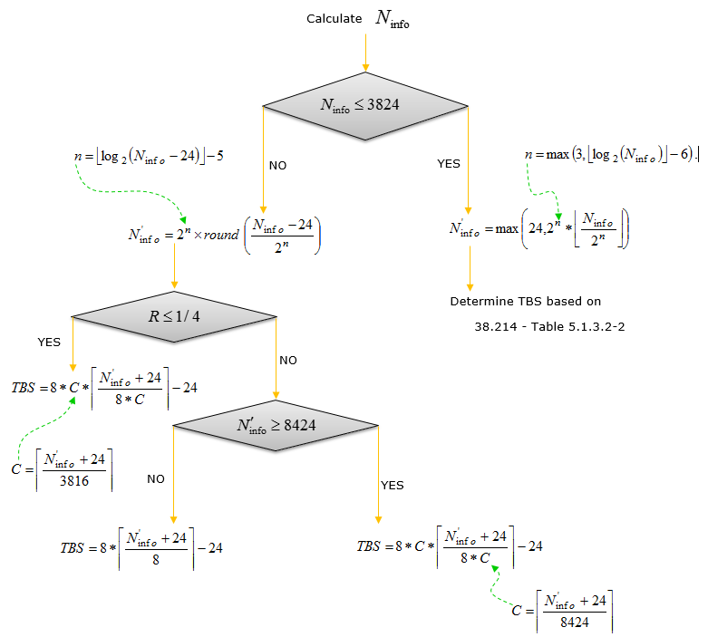
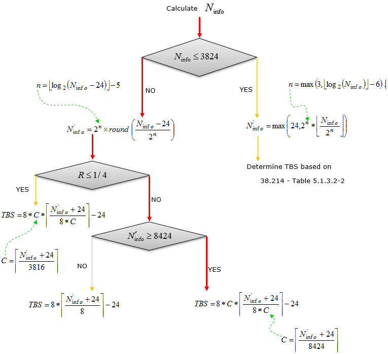
Step 3 is the long one, and the rest of this page is about it. It runs in two stages. The first stage counts the resource elements the grant provides and turns them into N_info. The second stage quantises N_info into a transport block size.
Keeping those two stages apart helps while reading the sections below. The first stage is arithmetic on the grant, and every term in it comes from the scheduling decision. The second stage is pure quantisation, and it depends only on N_info and on the code rate.
Choosing the table is the hard part of Step 1 : The RNTI, the DCI format and the configured mcs-Table parameter decide it together.RV does not change TBS : Redundancy version selects part of the circular buffer, so a retransmission carries the same transport block size.Step 3 runs in two stages : N_info is computed from the grant, and then quantised into a transport block size.The quantisation has a reason : It makes the transport block divide cleanly into LDPC code blocks, which is why the thresholds 3824 and 8424 appear in the flow chart.
PDSCH Transport Block Size Determination
NR MCS and Code Rate are determined by a predefined table as in 38.214 - Table 5.1.3.1-1 and 38.214 - Table 5.1.3.1-2, which is pretty straight forward. However, determining TBS (Transport block size) in NR is more complicated than the one in LTE. In case of LTE, all the possibility of TBS are precalculated and listed as a big table. However, in NR the TBS determination process is described as a sequence of algorithm as summarized below (I think it will take a while to get familiar with this process).
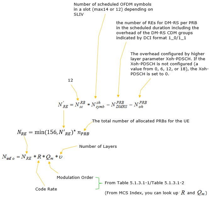
< Calculate N_info >
As you see in the process illustrated above, the initial input for this algorithm is Ninfo. However, to figure out this Ninfo also requires long calculation process as below.
< 38.214 - Table 5.1.3.1-1: MCS index table 1 for PDSCH >
|
MCS Index IMCS |
Modulation Order Qm |
Target code Rate x [1024] R |
Spectral efficiency |
|
0 |
2 |
120 |
0.2344 |
|
1 |
2 |
157 |
0.3066 |
|
2 |
2 |
193 |
0.3770 |
|
3 |
2 |
251 |
0.4902 |
|
4 |
2 |
308 |
0.6016 |
|
5 |
2 |
379 |
0.7402 |
|
6 |
2 |
449 |
0.8770 |
|
7 |
2 |
526 |
1.0273 |
|
8 |
2 |
602 |
1.1758 |
|
9 |
2 |
679 |
1.3262 |
|
10 |
4 |
340 |
1.3281 |
|
11 |
4 |
378 |
1.4766 |
|
12 |
4 |
434 |
1.6953 |
|
13 |
4 |
490 |
1.9141 |
|
14 |
4 |
553 |
2.1602 |
|
15 |
4 |
616 |
2.4063 |
|
16 |
4 |
658 |
2.5703 |
|
17 |
6 |
438 |
2.5664 |
|
18 |
6 |
466 |
2.7305 |
|
19 |
6 |
517 |
3.0293 |
|
20 |
6 |
567 |
3.3223 |
|
21 |
6 |
616 |
3.6094 |
|
22 |
6 |
666 |
3.9023 |
|
23 |
6 |
719 |
4.2129 |
|
24 |
6 |
772 |
4.5234 |
|
25 |
6 |
822 |
4.8164 |
|
26 |
6 |
873 |
5.1152 |
|
27 |
6 |
910 |
5.3320 |
|
28 |
6 |
948 |
5.5547 |
|
29 |
2 |
reserved |
|
|
30 |
4 |
reserved |
|
|
31 |
6 |
reserved |
|
< 38.214 - Table 5.1.3.1-2: MCS index table 2 for PDSCH >
|
MCS Index IMCS |
Modulation Order Qm |
Target code Rate x [1024] R |
Spectral efficiency |
|
0 |
2 |
120 |
0.2344 |
|
1 |
2 |
193 |
0.377 |
|
2 |
2 |
308 |
0.6016 |
|
3 |
2 |
449 |
0.877 |
|
4 |
2 |
602 |
1.1758 |
|
5 |
4 |
378 |
1.4766 |
|
6 |
4 |
434 |
1.6953 |
|
7 |
4 |
490 |
1.9141 |
|
8 |
4 |
553 |
2.1602 |
|
9 |
4 |
616 |
2.4063 |
|
10 |
4 |
658 |
2.5703 |
|
11 |
6 |
466 |
2.7305 |
|
12 |
6 |
517 |
3.0293 |
|
13 |
6 |
567 |
3.3223 |
|
14 |
6 |
616 |
3.6094 |
|
15 |
6 |
666 |
3.9023 |
|
16 |
6 |
719 |
4.2129 |
|
17 |
6 |
772 |
4.5234 |
|
18 |
6 |
822 |
4.8164 |
|
19 |
6 |
873 |
5.1152 |
|
20 |
8 |
682.5 |
5.332 |
|
21 |
8 |
711 |
5.5547 |
|
22 |
8 |
754 |
5.8906 |
|
23 |
8 |
797 |
6.2266 |
|
24 |
8 |
841 |
6.5703 |
|
25 |
8 |
885 |
6.9141 |
|
26 |
8 |
916.5 |
7.1602 |
|
27 |
8 |
948 |
7.4063 |
|
28 |
2 |
reserved |
|
|
29 |
4 |
reserved |
|
|
30 |
6 |
reserved |
|
|
31 |
8 |
reserved |
|
< 38.214 - Table 5.1.3.1-3: MCS index table 3 for PDSCH >
|
MCS Index IMCS |
Modulation Order Qm |
Target code Rate x [1024] R |
Spectral efficiency |
|
0 |
2 |
30 |
0.0586 |
|
1 |
2 |
40 |
0.0781 |
|
2 |
2 |
50 |
0.0977 |
|
3 |
2 |
64 |
0.1250 |
|
4 |
2 |
78 |
0.1523 |
|
5 |
2 |
99 |
0.1934 |
|
6 |
2 |
120 |
0.2344 |
|
7 |
2 |
157 |
0.3066 |
|
8 |
2 |
193 |
0.3770 |
|
9 |
2 |
251 |
0.4902 |
|
10 |
2 |
308 |
0.6016 |
|
11 |
2 |
379 |
0.7402 |
|
12 |
2 |
449 |
0.8770 |
|
13 |
2 |
526 |
1.0273 |
|
14 |
2 |
602 |
1.1758 |
|
15 |
4 |
340 |
1.3281 |
|
16 |
4 |
378 |
1.4766 |
|
17 |
4 |
434 |
1.6953 |
|
18 |
4 |
490 |
1.9141 |
|
19 |
4 |
553 |
2.1602 |
|
20 |
4 |
616 |
2.4063 |
|
21 |
6 |
438 |
2.5664 |
|
22 |
6 |
466 |
2.7305 |
|
23 |
6 |
517 |
3.0293 |
|
24 |
6 |
567 |
3.3223 |
|
25 |
6 |
616 |
3.6094 |
|
26 |
6 |
666 |
3.9023 |
|
27 |
6 |
719 |
4.2129 |
|
28 |
6 |
772 |
4.5234 |
|
29 |
2 |
reserved |
|
|
30 |
4 |
reserved |
|
|
31 |
6 |
reserved |
|
< 38.214 - Table 5.1.3.2-1: TBS for N_info <= 3824 >
|
Index |
TBS |
Index |
TBS |
Index |
TBS |
Index |
TBS |
|
1 |
24 |
31 |
336 |
61 |
1288 |
91 |
3624 |
|
2 |
32 |
32 |
352 |
62 |
1320 |
92 |
3752 |
|
3 |
40 |
33 |
368 |
63 |
1352 |
93 |
3824 |
|
4 |
48 |
34 |
384 |
64 |
1416 |
|
|
|
5 |
56 |
35 |
408 |
65 |
1480 |
|
|
|
6 |
64 |
36 |
432 |
66 |
1544 |
|
|
|
7 |
72 |
37 |
456 |
67 |
1608 |
|
|
|
8 |
80 |
38 |
480 |
68 |
1672 |
|
|
|
9 |
88 |
39 |
504 |
69 |
1736 |
|
|
|
10 |
96 |
40 |
528 |
70 |
1800 |
|
|
|
11 |
104 |
41 |
552 |
71 |
1864 |
|
|
|
12 |
112 |
42 |
576 |
72 |
1928 |
|
|
|
13 |
120 |
43 |
608 |
73 |
2024 |
|
|
|
14 |
128 |
44 |
640 |
74 |
2088 |
|
|
|
15 |
136 |
45 |
672 |
75 |
2152 |
|
|
|
16 |
144 |
46 |
704 |
76 |
2216 |
|
|
|
17 |
152 |
47 |
736 |
77 |
2280 |
|
|
|
18 |
160 |
48 |
768 |
78 |
2408 |
|
|
|
19 |
168 |
49 |
808 |
79 |
2472 |
|
|
|
20 |
176 |
50 |
848 |
80 |
2536 |
|
|
|
21 |
184 |
51 |
888 |
81 |
2600 |
|
|
|
22 |
192 |
52 |
928 |
82 |
2664 |
|
|
|
23 |
208 |
53 |
984 |
83 |
2728 |
|
|
|
24 |
224 |
54 |
1032 |
84 |
2792 |
|
|
|
25 |
240 |
55 |
1064 |
85 |
2856 |
|
|
|
26 |
256 |
56 |
1128 |
86 |
2976 |
|
|
|
27 |
272 |
57 |
1160 |
87 |
3104 |
|
|
|
28 |
288 |
58 |
1192 |
88 |
3240 |
|
|
|
29 |
304 |
59 |
1224 |
89 |
3368 |
|
|
|
30 |
320 |
60 |
1256 |
90 |
3496 |
|
|
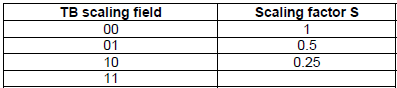
< 38.214 v16.9 - Table 5.1.3.2-2: Scaling factor of Ninfo for P-RNTI, RA-RNTI and MSGB-RNTI >
< Calculate TBS from N_info >
This is an illustration based on 38.214 - 5.1.3.2 Transport block size determination.
PUSCH Transport Block Size Determination
PUSCH Transport block size is influenced by RRC Parameters at the stage of determining Modulation Order and Code Rate and this makes it so difficult and complicated to understand the whole process of TBS(Transport Size) Determination. The RRC parameters involved in this process is highlighted in red as shown below.
Following is based on
PUSCH-Config ::= SEQUENCE {
dataScramblingIdentityPUSCH INTEGER (0..1023) OPTIONAL,
txConfig ENUMERATED {codebook, nonCodebook}
dmrs-UplinkForPUSCH-MappingTypeA SetupRelease { DMRS-UplinkConfig }
dmrs-UplinkForPUSCH-MappingTypeB SetupRelease { DMRS-UplinkConfig }
pusch-PowerControl PUSCH-PowerControl
frequencyHopping ENUMERATED {intraSlot, interSlot}
frequencyHoppingOffsetLists SEQUENCE (SIZE (1..4)) OF
INTEGER (1.. maxNrofPhysicalResourceBlocks-1)
resourceAllocation ENUMERATED { resourceAllocationType0,
resourceAllocationType1,
dynamicSwitch},
pusch-TimeDomainAllocationList SetupRelease {
PUSCH-TimeDomainResourceAllocationList
}
pusch-AggregationFactor ENUMERATED { n2, n4, n8 }
mcs-Table ENUMERATED {qam256, qam64LowSE}
mcs-TableTransformPrecoder ENUMERATED {qam256, qam64LowSE}
transformPrecoder ENUMERATED {enabled, disabled}
codebookSubset ENUMERATED {fullyAndPartialAndNonCoherent,
partialAndNonCoherent,
nonCoherent}
maxRank INTEGER (1..4)
rbg-Size ENUMERATED { config2}
uci-OnPUSCH SetupRelease { UCI-OnPUSCH }
tp-pi2BPSK ENUMERATED {enabled}
...
}
ConfiguredGrantConfig ::= SEQUENCE {
frequencyHopping ENUMERATED {intraSlot, interSlot} ,
cg-DMRS-Configuration DMRS-UplinkConfig,
mcs-Table ENUMERATED {qam256, qam64LowSE}
mcs-TableTransformPrecoder ENUMERATED {qam256, qam64LowSE}
uci-OnPUSCH SetupRelease { CG-UCI-OnPUSCH } OPTIONAL,
resourceAllocation ENUMERATED { resourceAllocationType0,
resourceAllocationType1,
dynamicSwitch },
rbg-Size ENUMERATED {config2},
powerControlLoopToUse ENUMERATED {n0, n1},
p0-PUSCH-Alpha P0-PUSCH-AlphaSetId,
transformPrecoder ENUMERATED {enabled, disabled},
nrofHARQ-Processes INTEGER(1..16),
repK ENUMERATED {n1, n2, n4, n8},
repK-RV ENUMERATED {s1-0231, s2-0303, s3-0000},
periodicity ENUMERATED {
sym2, sym7, sym1x14, sym2x14, sym4x14,
sym5x14, sym8x14, sym10x14, sym16x14,
sym20x14,sym32x14, sym40x14, sym64x14,
sym80x14, sym128x14, sym160x14, sym256x14,
sym320x14, sym512x14,sym640x14, sym1024x14,
sym1280x14, sym2560x14, sym5120x14,sym6,
sym1x12, sym2x12, sym4x12, sym5x12,
sym8x12, sym10x12, sym16x12, sym20x12,
sym32x12,sym40x12, sym64x12, sym80x12,
sym128x12, sym160x12, sym256x12, sym320x12,
sym512x12, sym640x12,sym1280x12, sym2560x12
},
configuredGrantTimer INTEGER (1..64) OPTIONAL, -- Need R
rrc-ConfiguredUplinkGrant SEQUENCE {
timeDomainOffset INTEGER (0..5119),
timeDomainAllocation INTEGER (0..15),
frequencyDomainAllocation BIT STRING (SIZE(18)),
antennaPort INTEGER (0..31),
dmrs-SeqInitialization INTEGER (0..1),
precodingAndNumberOfLayers INTEGER (0..63),
srs-ResourceIndicator INTEGER (0..15),
mcsAndTBS INTEGER (0..31),
frequencyHoppingOffset
INTEGER (1.. maxNrofPhysicalResourceBlocks-1)
pathlossReferenceIndex
INTEGER (0..maxNrofPUSCH-PathlossReferenceRSs-1)
...
} OPTIONAL, -- Need R
...
}
Both listings above are still accurate in Release 19. Every field quoted is present in 38.331 v19.3.0, and the order is unchanged. What later releases added is a second copy of the modulation table fields, and the copies are what decide the table in Step 1 above.
Following is based on
PUSCH-Config ::= SEQUENCE {
....
....
}
PDSCH-Config ::= SEQUENCE {
....
mcs-Table ENUMERATED {qam256, qam64LowSE} OPTIONAL, -- Need S
....
}
Release 16 added one table field per compact DCI format. So a UE can be told to use one MCS table when the grant arrives in DCI format 0_1. It can be told to use a different table when the same grant arrives in DCI format 0_2. Reading mcs-Table on its own is therefore not enough to decide the table for a given grant.
Release 17 added the two fields that select the 1024QAM table. When mcs-Table-r17 is set to qam1024, and the PDSCH is scheduled by DCI format 1_1 or 1_3 with a CRC scrambled by C-RNTI, the UE reads 38.214 Table 5.1.3.1-4. That is the table where Qm reaches 10.
Three things follow for anyone decoding a live grant. Every field quoted above is still current in 38.331 v19.3.0. The table in use depends on the DCI format as well as on the configuration. And 1024QAM has its own selector, which is mcs-Table-r17.
< Modulation order and target code rate determination >
I created following table based on the descriptions in 38.214-6.1.4.1(v15.3 - Oct 2018).
|
Transform Precoding |
mcs-Table |
mcs-Table TransformPrecoder |
RNTI |
DCI |
MCS Index Table |
||
|
PUSCH-Config |
Configured GrantConfig |
PUSCH-Config |
Configured GrantConfig |
||||
|
diabled |
qam256 |
N/A |
N/A |
C-RNTI SP-CSI-RNTI |
0_1 |
||
|
diabled |
qam64LowSE |
N/A |
N/A |
NOT MCS-C-RNTI C-RNTI SP-CSI-RNTI |
|
||
|
diabled |
N/A |
qam256 |
N/A |
MCS-C-RNT |
|
||
|
diabled |
N/A |
qam64LowSE |
N/A |
CS-RNTI |
|
||
|
diabled |
none of the above |
||||||
|
enabled |
qam256 |
|
|
C-RNTI SP-CSI-RNTI |
0_1 |
||
|
enabled |
qam64LowSE |
|
|
NOT MCS-C-RNTI C-RNTI SP-CSI-RNTI |
|
6.1.4.1-2 |
|
|
enabled |
|
|
|
MCS-C-RNT |
|
6.1.4.1-2 |
|
|
enabled |
|
qam256 |
|
CS-RNTI |
|
||
|
enabled |
|
qam64LowSE |
|
CS-RNTI |
|
6.1.4.1-2 |
|
|
enabled |
none of the above |
6.1.4.1-1 |
|||||
< Transport block size determination >
I created following summary based on the descriptions in 38.214-6.1.4.2 (v15.3 - Oct 2018).
NOTE : The condition for this case is described in 38.214-6.1.4.2 (v15.3 - Oct 2018) as follows. At first, it looks very confusing. It looked like three different 'if statement' with conflicting condition. But looking more closely, I realized all of these three lines makes up a single 'if statement'. You see all of these three lines are combined by 'or'.
- 0 <= I_MCS <≤ 27 and transform precoding is disabled and Table 5.1.3.1-2 is used, or
- 0 <≤ I_MCS <≤ 28 and transform precoding is disabled and a table other than Table 5.1.3.1-2 is used, or
- 0 <≤ I_MCS <≤ 27 and transform precoding is enabled
First Calculate N'_RE using following formula
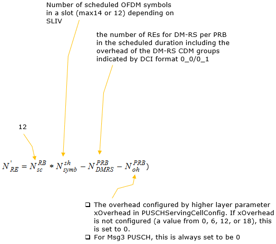
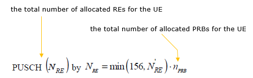
Next Calculate the total number of REs for PUSCH as follows.
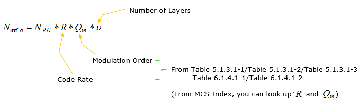
Next Calculate Ninfo as follows :
Next step is same as downlink TBS determination process as shown below.
Max Throughput Estimation
There are roughly two approaches to estimate the max throughput. One of the most popular or best known method is to use the formula specified in 38.306-4.1.2. But this method would tend to give much higher value than you normally achieve in real life testing since it is hard to take into consider various overhead that you face.
In my opinion, more accurate method is to estimate TBS for each slot within a radio frame and multiply the number with the number of radio frames per second.
Method 1 : based on 38.306
This method is explained in a different page here.
Method 2 : based on TBS
This is based on the transport block size (TBS) estimation explained in this page. As you see in this page, this method goes through a little bit complicated process, so I wrote a Octave script to estimate the throughput as shown below.
NOTE : This is not the perfect/complete script. For simplicity, I only implemented the high throughput path as indicated by red arrow below. I used Code Rate (R) value from 38.214 -Table 5.1.3.1-1 and Table 5.1.3.1-2, but real code rate can vary a little bit from the value in the table... but you can use the table value as a rough estimator.
|
function main
NofSlotsPerRadioFrame = 20 NofRadioFramePerSec = 100 NRB_sc = 12 Nsh_symb = 13 NPRB_oh = 0
nPRB = 273 Qm = 8 % This is for MCS 20 in 256QAM Table %R = 0.6825 % This is for MCS 20 in 256QAM Table R = 0.948 % This is for MCS 27 in 256QAM Table
v = 4 % Number of Layers
NPRB_DMRS = DMRS_RE("type1","A",1,0) %NPRB_DMRS = DMRS_RE("type1","A",2,0) %NPRB_DMRS = DMRS_RE("type1","A",2,3) NREprime = NRB_sc * Nsh_symb - NPRB_DMRS - NPRB_oh NREbar = min(156, NREprime)
NRE = NREbar * nPRB Ninfo = NRE * R * Qm * v
if (Ninfo > 3824) n = floor(log2(Ninfo - 24)) - 5 Ninfo_prime = 2^n * round( (Ninfo - 24)/(2^n) ) if (R > 0.25) if (Ninfo_prime > 8424) C = ceil( (Ninfo_prime + 24)/8424 ) TBS_bits = 8 * C * ceil( (Ninfo_prime + 24)/(8*C) ) - 24 TBS_bytes = TBS_bits / 8 endif endif endif
TP_bps = TBS_bits * NofSlotsPerRadioFrame * NofRadioFramePerSec TP_Mbps = TP_bps / (1024*1024)
endfunction
function dmrsRE = DMRS_RE(type,mapping,len,addPos)
if(type == "type1") DMRSType = "type1" if(mapping == "A") PDSCH_MappingType = "A" maxLength = len if(addPos == 0) dmrsRE = 6 * len; elseif (addPos == 1) dmrsRE = 2 * 6 * len; elseif (addPos == 2) dmrsRE = 3 * 6 * len; elseif (addPos == 3) dmrsRE = 4 * 6 * len; endif; AdditionalPos = addPos; elseif(mapping == "B") dmrsRE = 6 * len; endif else DMRSType = "type1" if(mapping == "B") PDSCH_MappingType = "A" maxLength = len if(addPos == 0) dmrsRE = 4 * len; elseif (addPos == 1) dmrsRE = 2 * 4 * len; elseif (addPos == 2) dmrsRE = 3 * 4 * len; elseif (addPos == 3) dmrsRE = 4 * 4 * len; endif; AdditionalPos = addPos; elseif(mapping == "B") dmrsRE = 4 * len; endif endif
endfunction |
Following is the result of an example run
|
NofSlotsPerRadioFrame = 20 NofRadioFramePerSec = 100 NRB_sc = 12 Nsh_symb = 13 NPRB_oh = 0 nPRB = 273 Qm = 8 v = 4 DMRSType = type1 PDSCH_MappingType = A maxLength = 1 NPRB_DMRS = 6 NREprime = 150 NREbar = 150 NRE = 40950 Ninfo = 1242259.20000 n = 15 Ninfo_prime = 1245184 C = 148 TBS_bits = 1245544 TBS_bytes = 155693 TP_bps = 2491088000 TP_Mbps = 2375.7 |
Reference
[1]