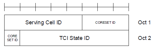
The TCI State Indication for UE-specific PDCCH MAC CE is a fixed-size Control Element that spans 16 bits and is comprised of three specific fields, each with a designated length and purpose. This MAC CE is crucial for the UE as it dictates the current transmission configuration(TCI) for decoding the PDCCH, which is essential for the UE to understand the downlink scheduling decisions made by the gNodeB.
< 38.321-Figure 6.1.3.15-1: TCI State Indication for UE-specific PDCCH MAC CE >
- What is a TCI state, and why does PDCCH need one ?
- Why does this MAC CE indicate one state rather than activate several ?
- How do the three fields sit inside the two octets ?
- When does the new TCI state take effect, and what came after ?
- Examples
- Reference
What is a TCI state, and why does PDCCH need one ?
The field descriptions above tell you that the MAC CE selects a TCI state. They do not say what a TCI state is, and I found that the part worth pinning down first.
TCI stands for Transmission Configuration Indication. A TCI state does not describe a beam directly. It names one or two reference signals. It then says which properties of the received signal are shared with them. That relationship is called quasi co-location, or QCL.
Each TCI state holds up to two QCL entries. The first names a reference signal with QCL-TypeA, TypeB or TypeC, which cover Doppler shift, Doppler spread, average delay and delay spread. Those are the properties a receiver needs for time and frequency tracking.
The second entry is the one this MAC CE exists for. It carries QCL-TypeD, which is the spatial receive parameter. Telling a UE that the PDCCH is QCL-TypeD with a particular SSB tells it which receive beam to use. That entry is optional, because a UE below 6 GHz often needs no receive beam at all.
So the chain runs backwards from the MAC CE. The MAC CE names a TCI state, and the TCI state names a reference signal. That reference signal is one the UE has already measured and can point a beam at.
Figure 1. The TCI State ID field in this MAC CE selects one of these. Everything the UE needs in order to receive the PDCCH follows from the reference signals it names.
A TCI state is a QCL relationship, not a beam : It names reference signals, and says what is shared with them.QCL-TypeD is the beam entry : It carries the spatial receive parameter, so it tells the UE where to point.The other QCL types are for tracking : Doppler and delay properties, which a receiver needs whether or not beams are involved.The TypeD entry is optional : Below 6 GHz a UE often needs no receive beam. Only the tracking entry is then present.The reference signal is already known : It is an SSB or CSI-RS the UE has measured, which is what makes the indication usable.
Why does this MAC CE indicate one state rather than activate several ?
Its sibling for PDSCH, at LCID 53, is called an Activation and Deactivation. It switches on as many as eight TCI states at once. This one, at LCID 52, is called an Indication and it names exactly one. The difference in the names is a real difference in what each has to achieve.
PDSCH narrows its choice in three stages. RRC configures as many as 128 TCI states. A MAC CE activates up to eight of them. A three-bit field in the scheduling DCI then picks one of those eight for the transmission it is scheduling. That last stage is what lets the beam change from one slot to the next.
PDCCH cannot use that last stage, and the reason is circular. The DCI is carried on the PDCCH. A field inside the DCI cannot tell the UE how to receive the PDCCH. The UE has to receive the PDCCH before it can read that field. The beam has to be settled before decoding begins.
So the MAC CE has to be the final word. It names one TCI state for one CORESET, and the UE uses that state until another MAC CE replaces it. There is no faster mechanism underneath, which is also why PDCCH beam changes are coarser in time than PDSCH beam changes.
Figure 2. The missing third stage is not an omission. It is the reason the MAC CE has to settle the answer on its own.
PDSCH narrows in three stages : RRC configures up to 128. A MAC CE activates up to 8, and a DCI field picks 1.PDCCH has no third stage : A DCI field cannot describe how to receive the DCI that carries it.The MAC CE is therefore final : It names one state per CORESET. That state holds until another MAC CE replaces it.The names reflect the difference : Indication for PDCCH at LCID 52, Activation and Deactivation for PDSCH at LCID 53.PDCCH beams change more slowly : There is no per-slot selection underneath the MAC CE to make them faster.
How do the three fields sit inside the two octets ?
Sixteen bits split three ways does not divide evenly, and the specification figure shows what that costs. The CORESET ID does not fit inside one octet.
|
Field |
Width |
Where it sits |
RRC range it has to cover |
|---|---|---|---|
|
|
5 bits |
Octet 1, the first five bits |
Up to 32 serving cells, so 5 bits is exact |
|
|
4 bits |
Three bits in octet 1, one bit in octet 2 |
ControlResourceSetId runs 0 to 11, so 4 bits covers it |
|
|
7 bits |
Octet 2, the last seven bits |
TCI-StateId runs 0 to 127, so 7 bits is exact |
Two things follow from that table. The first is that every field is exactly as wide as it needs to be. Five bits address 32 serving cells, seven bits address 128 TCI states, and neither has a spare bit. The MAC CE was sized against the RRC ranges rather than against octet boundaries.
The second is the consequence of that choice. The CORESET ID straddles the boundary. Three of its bits sit at the end of octet 1, and the fourth at the start of octet 2. A decoder that reads octet by octet has to reassemble it. A trace showing the two octets separately will not show the CORESET ID as a single number.
The CORESET ID also carries a special case that the field description above states without explaining. A value of 0 refers to the CORESET configured by controlResourceSetZero. The UE learns that one from the MIB and SIB1, long before any dedicated configuration. That CORESET therefore has no TCI state list of its own to point into. For that one value the TCI State ID is read against the first 64 states configured in PDSCH-Config instead. That is why the field description names a different list for CORESET 0.
Every field is sized to its RRC range : 5 bits for 32 cells and 7 bits for 128 TCI states, with nothing spare.The CORESET ID straddles the octet boundary : Three bits end octet 1, and one bit starts octet 2.Octet-wise reading is not enough : A decoder has to reassemble the CORESET ID from two octets before it means anything.CORESET 0 has no list of its own : It comes from the MIB and SIB1. The TCI State ID is read against the first 64 states in PDSCH-Config.One MAC CE can reach several cells : Where the serving cell is in a simultaneousTCI-UpdateList, the indication covers that whole list.
When does the new TCI state take effect, and what came after ?
A beam indication that took effect immediately would be unusable, because the UE has to finish receiving the message that carries it. The specification therefore defines a delay.
TS 38.214 measures that delay from the acknowledgement rather than from the reception. Call n the slot in which the UE sent the HARQ acknowledgement for the transport block carrying this MAC CE. The UE applies the indicated TCI state from the first slot after slot n plus three subframes worth of slots. Counting from the acknowledgement is what makes the gNB and the UE agree, because the gNB knows when the acknowledgement arrived.
The practical consequence appears when reading a log. A PDCCH that still arrives on the old beam shortly after the MAC CE is not a failure. It is inside the application window. That window is measured in slots, so its length in milliseconds follows the subcarrier spacing.
This MAC CE also has descendants. The family grew past the LCID space and continued in the extended range. There the specification defines an Enhanced TCI States Indication for UE-specific PDCCH. Release 17 then introduced the unified TCI framework. One indication there covers several channels at once. The MAC CE on this page remains the one that a Release 15 or Release 16 UE uses for PDCCH.
The delay is counted from the acknowledgement : Three subframes worth of slots after the slot carrying the HARQ acknowledgement.Counting from the acknowledgement keeps both ends in step : The gNB knows when it arrived, so both compute the same instant.The window is in slots, not milliseconds : Its duration therefore depends on the subcarrier spacing.The old beam inside the window is not a fault : A PDCCH still arriving on it is expected there.Later releases extended the family : An enhanced indication lives in the extended LCID range. Release 17 added the unified TCI framework.
Examples
Four cases cover most of what this MAC CE is used for. Each one shows the RRC that has to exist first. Then the field values the MAC CE carries, and what the UE does with them.
Each example gives two tables. The first says what the MAC CE means. The second shows how those values are packed, one bit per column, with bit 7 leftmost. The CORESET ID is the one to watch, because it is split across the two octets.
Example 1 : first beam indication for a dedicated CORESET
RRC has configured a CORESET and given it a list of candidate TCI states. Nothing has selected one yet, so the UE has no beam for this CORESET.
ControlResourceSet ::= SEQUENCE {
controlResourceSetId 1,
duration 2,
tci-StatesPDCCH-ToAddList { 3, 5, 12, 41 },
...
}
TCI-State ::= SEQUENCE {
tci-StateId 5,
qcl-Type1 { referenceSignal ssb : 2, qcl-Type typeC },
qcl-Type2 { referenceSignal ssb : 2, qcl-Type typeD }
}
The gNB now selects TCI state 5 for CORESET 1 on the primary cell.
|
Serving Cell ID |
CORESET ID |
TCI State ID |
|---|---|---|
|
0 |
1 |
5 |
Reading the bits out gives the two octets that travel, 0x00 0x85.
|
Octet |
bit 7 |
bit 6 |
bit 5 |
bit 4 |
bit 3 |
bit 2 |
bit 1 |
bit 0 |
Hex |
|---|---|---|---|---|---|---|---|---|---|
|
Octet 1 |
Serving Cell ID |
CORESET ID (bits 3 to 1) |
0x00 |
||||||
|
0 |
0 |
0 |
0 |
0 |
0 |
0 |
0 |
||
|
Octet 2 |
CORESET ID (bit 0) |
TCI State ID |
0x85 |
||||||
|
1 |
0 |
0 |
0 |
0 |
1 |
0 |
1 |
||
The UE reads TCI state 5 and follows it to SSB 2. It then points the beam it used for SSB 2 at CORESET 1. Note that only the four states in tci-StatesPDCCH-ToAddList are selectable here. A TCI State ID outside that list would be meaningless for this CORESET.
Example 2 : switching the beam on the same CORESET
The UE has moved and now reports a better measurement on SSB 6, which TCI state 12 refers to. No RRC signalling is involved, because state 12 was already in the list from Example 1.
|
Serving Cell ID |
CORESET ID |
TCI State ID |
|---|---|---|
|
0 |
1 |
12 |
Reading the bits out gives the two octets that travel, 0x00 0x8C.
|
Octet |
bit 7 |
bit 6 |
bit 5 |
bit 4 |
bit 3 |
bit 2 |
bit 1 |
bit 0 |
Hex |
|---|---|---|---|---|---|---|---|---|---|
|
Octet 1 |
Serving Cell ID |
CORESET ID (bits 3 to 1) |
0x00 |
||||||
|
0 |
0 |
0 |
0 |
0 |
0 |
0 |
0 |
||
|
Octet 2 |
CORESET ID (bit 0) |
TCI State ID |
0x8C |
||||||
|
1 |
0 |
0 |
0 |
1 |
1 |
0 |
0 |
||
Only one octet changed. This is the ordinary beam switching case. It is why the candidate list is configured once and then left alone. A beam change costs one MAC CE, not a reconfiguration.
The UE keeps the old beam until the delay described in When does the new TCI state take effect has passed.
Example 3 : CORESET 0, where the state list comes from elsewhere
CORESET 0 comes from the MIB and SIB1, so it has no tci-StatesPDCCH-ToAddList of its own. The TCI State ID is read against the first 64 states in PDSCH-Config instead.
PDSCH-Config ::= SEQUENCE {
tci-StatesToAddModList {
{ tci-StateId 0, ... },
{ tci-StateId 1, ... },
{ tci-StateId 3, qcl-Type1 { ssb : 4, typeC }, qcl-Type2 { ssb : 4, typeD } },
...
},
...
}
|
Serving Cell ID |
CORESET ID |
TCI State ID |
|---|---|---|
|
0 |
0 |
3 |
Reading the bits out gives the two octets that travel, 0x00 0x03.
|
Octet |
bit 7 |
bit 6 |
bit 5 |
bit 4 |
bit 3 |
bit 2 |
bit 1 |
bit 0 |
Hex |
|---|---|---|---|---|---|---|---|---|---|
|
Octet 1 |
Serving Cell ID |
CORESET ID (bits 3 to 1) |
0x00 |
||||||
|
0 |
0 |
0 |
0 |
0 |
0 |
0 |
0 |
||
|
Octet 2 |
CORESET ID (bit 0) |
TCI State ID |
0x03 |
||||||
|
0 |
0 |
0 |
0 |
0 |
0 |
1 |
1 |
||
The CORESET ID of 0 is what changes the lookup. For any other CORESET ID the same value points into that CORESET's own list. A decoder ignoring this rule resolves the beam against the wrong list.
Example 4 : one indication covering several serving cells
The UE is configured with carrier aggregation across cells that share a beam. RRC places those cells in a simultaneous update list, which lives in CellGroupConfig.
CellGroupConfig ::= SEQUENCE {
...
simultaneousTCI-UpdateList1-r16 { 2, 3, 4 },
...
}
|
Serving Cell ID |
CORESET ID |
TCI State ID |
|---|---|---|
|
2 |
2 |
9 |
Reading the bits out gives the two octets that travel, 0x11 0x09.
|
Octet |
bit 7 |
bit 6 |
bit 5 |
bit 4 |
bit 3 |
bit 2 |
bit 1 |
bit 0 |
Hex |
|---|---|---|---|---|---|---|---|---|---|
|
Octet 1 |
Serving Cell ID |
CORESET ID (bits 3 to 1) |
0x11 |
||||||
|
0 |
0 |
0 |
1 |
0 |
0 |
0 |
1 |
||
|
Octet 2 |
CORESET ID (bit 0) |
TCI State ID |
0x09 |
||||||
|
0 |
0 |
0 |
0 |
1 |
0 |
0 |
1 |
||
The MAC CE names serving cell 2, and serving cell 2 is a member of simultaneousTCI-UpdateList1. The indication therefore applies to serving cells 2, 3 and 4 together. CORESET 2 on each of them takes TCI state 9. One MAC CE has done the work of three.
This only works where the cells genuinely share a beam, which in practice means intra-band carrier aggregation. Cells on widely separated carriers need separate indications.
The candidate list is configured once : Beam switching after that costs one MAC CE, with no RRC signalling at all.Only the configured states are selectable : A TCI State ID outside the CORESET's list means nothing for that CORESET.CORESET 0 resolves against a different list : One TCI State ID value can mean two different states, depending on the CORESET ID.A simultaneous update list multiplies the reach : One indication can set the beam on every cell in the list.Octet 1 rarely changes : An ordinary beam switch alters only the TCI State ID, which lives in octet 2.
Reference
[1] 3GPP TS 38.321 - NR; Medium Access Control (MAC) protocol specification. Section 6.1.3.15 defines this MAC CE, and section 6.1.3.14 defines the PDSCH one.
[2] 3GPP TS 38.321 - Table 6.2.1-1 gives the DL-SCH LCID values, where this MAC CE is 52 and the PDSCH one is 53.
[3] 3GPP TS 38.331 - NR; Radio Resource Control (RRC) protocol specification. TCI-State, QCL-Info, ControlResourceSetId and simultaneousTCI-UpdateList are defined here.
[4] 3GPP TS 38.214 - NR; Physical layer procedures for data. Section 5.1.5 defines the QCL types and the delay before an indicated TCI state applies.
[5] MAC CE - the LCID and eLCID tables, and the MAC subheader formats, on this site.