As everybody knows, 5G(NR) is not the only cellular technology. We already have many different technology that has been deployed for many years from 2G to 4G. In terms of physical location, 5G(NR) may co-located (deployed at the same location) with every existing technlogy even though there might not be direct interaction or integration with those legacy technology. However, in terms of interaction / integration, it is highly likely that 5G(NR) will tightly integrate or interact with 4G(LTE). In this page, I will describe on various scenario and aspect of 5G deployment. Since this is at very high level description, it will be mostly explained by various illustrations (mostly from 3GPP document).
- Cell Layout
- RAN / Core Network Connection
- What do the deployment option numbers mean?
- How do the TR 38.804 cases map onto the RP-161266 options?
- Why did almost every operator start with Option 3x?
- Overall Radio Network Architecture
- Bearer Architecture for Dual Connectivity between LTE and NR
- Reference
Cell Layout
We can think of many different ways to layout 5G/NR cell. Some of the possible scenario is shown in this section based on TR 38.804. But there can still be more options which is completely new or modification of the cases shown here. What separates the three cases is not the technology. It is the relationship between the two coverage footprints. Case 1 has them equal, Case 2 has LTE larger, and Case 3 has NR larger. That relationship is decided by the NR frequency band before anything else is decided. A band below 1 GHz can match LTE range, and a band at 28 GHz cannot come close. You will see Case 1 described as the simple option. It is the hardest one to build, because it needs an NR band with LTE-like range. The cases below also separate co-located sites from non-co-located sites, which is a different question. Co-location decides how easy the X2 or Xn link is to build, and not how far the cell reaches.
< Case 1 >
In this scenario, LTE and NR are co-located/overlaid. It means NR cell is placed in the same location as LTE cell implying that NR cell use the same cell site and highly likely to use to same antenna tower. One thing to be noticed would be that LTE and NR coeverage is same. It implies that this scenario would not be the one for NR mmWave (FR2) since it will be very difficult to have such a wide cell coverage with NR mmWave. Even in FR1, this scenario would be tricky for the frequency band which is 3 Ghz or higher.
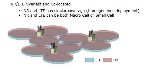
Figure 1. Case 1, a homogeneous deployment. NR and LTE share the site and the coverage footprint, which only works where the NR band is low enough to match LTE range.
< Case 2 >
Probably this may be a practical solution for early NR deployment where LTE takes the role of a master and NR takes the role of secondary cell. This can be applicable to both NR FR1(Sub 6) and FR2(mmWave).
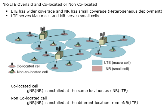
Figure 2. Case 2, a heterogeneous deployment with LTE as the macro layer. The NR small cells may sit on the LTE site or on their own site, and this is the layout most early NR deployments used.
< Case 3 >
I am not sure if we really see this type of deployment or not. In this scenario, NR is macro cell covering wide area and LTE is small cell which covers less area. It is likely to be assumed that NR cell work in SA(Standalone) mode in this scenario.
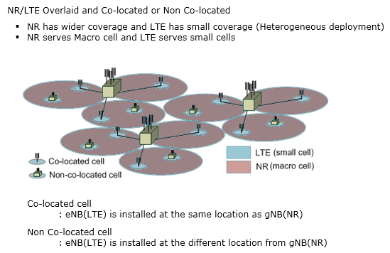
Figure 3. Case 3, the reverse heterogeneous layout. NR is the macro layer and LTE fills in as small cells, which assumes NR already runs standalone.
RAN / Core Network Connection
Even if the final goal of 5G/NR deployment would be to deploy 5G/NR in both RAN(Radio Access Network) and Core Network, it is not likely that this happen all at once from day one. So we may see (or think of) various intermediate steps from the first deployment to the final goal. 3GPP TR 38.804 and TDoc RP-161266 propose various options for the deployment. Even though RP-161266 came out much earlier than TR 38.804 and TR sounds more formal than RP, it seems that people still prefers to refer to RP 161266. However, whatever document you refer to, one thing obvious would be that we will see the deployment of NR with a LTE anchor at the early stage. This is Case 4 in TR 38.804 representation and Option 3/3a in RP-161266 representation. Regarding the options in RP-161266, I think there are articles that is written much better than I can do in terms of high level overview. Refer to Martin Sauter's two articles (this and this) and for more details on option3, refer to this page. In reality, this first stage option is implemented in a name called ENDC and you can use this page as a starting point of the detailed study. Two points make the figures below easier to read. The first is that the two documents number the same networks differently. This section shows TR 38.804 first and RP-161266 second, and a mapping between them follows further down. The second is that the option choice is a migration question rather than a design question. An operator is not selecting one of twelve architectures to keep forever. It is selecting the order in which to replace the radio and the core.
< TR 38.804 >
We can think of roughly two large catetories of RAN/Core Network connection. One is to use LTE cell as a Master and NR cell as a secondary cell. The other one is to use NR cell as a Master and LTE cell as a secondary. Within each categories, we can think of a few different options. In early deployment, it is likely to use < Case 4 > where LTE functions as a master and NR functions as a secondary cell.
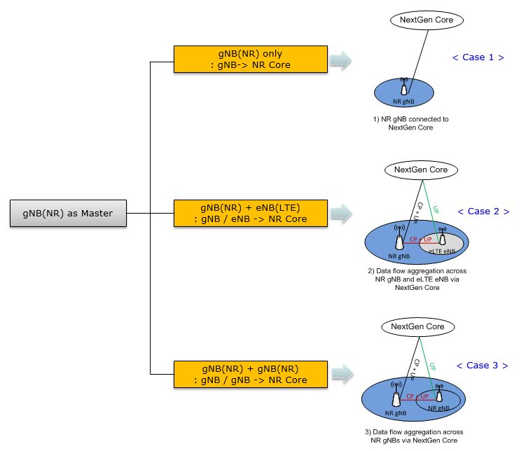
Figure 4. The TR 38.804 cases that have the gNB as master. Case 1 is NR alone on the NextGen Core, Case 2 aggregates NR with eLTE, and Case 3 aggregates two NR nodes.
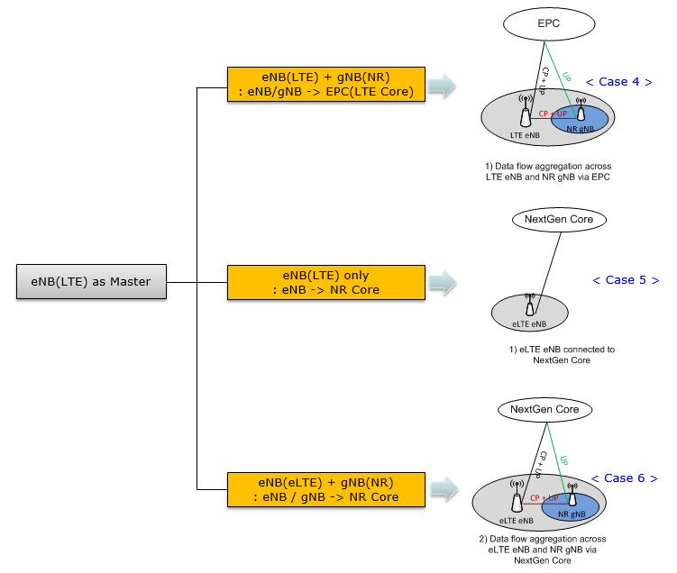
Figure 5. The TR 38.804 cases that have the eNB as master. Case 4 keeps the EPC, and it is the one that became the first commercial 5G deployment.
< RP-161266 >
RP-161266 is the numbering the industry actually adopted. It arranges twelve combinations of radio and core into one set of pictures. The figures below are the original ones, so they use the names of the time. NextGen Core is what became the 5G core, and eLTE eNB is what became the ng-eNB. The figures also share one drawing convention. Where both core boxes appear, the one with no line drawn to it is the core that is not in use.
< Option 1 and Option 2 >
These two are the endpoints, and neither one uses dual connectivity. Option 1 draws a single core and a single radio, both of them LTE. That is the network an operator already has before any 5G work begins. Option 2 draws the NextGen Core with an NR radio, and nothing else. Every option in between exists because operators could not move from the first picture to the second in one step.
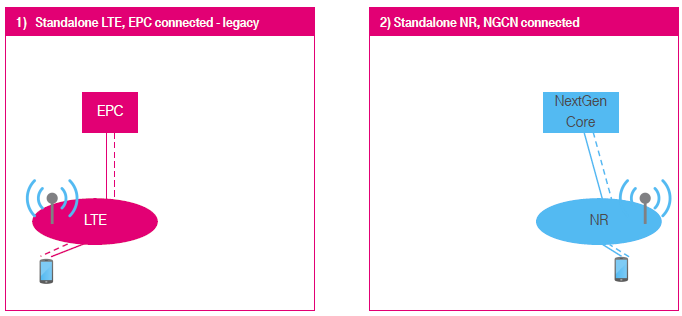
Figure 6. Options 1 and 2, the start point and the end point. Option 1 is the LTE network an operator already owns, and Option 2 is the standalone NR network it is trying to reach.
< Option 3 and Option 3a >
Both pictures keep the EPC and add an NR radio beside the LTE one. The NextGen Core box is drawn with no line to it, because it is not in use here. The short line between the LTE and NR ovals is the interface between the two base stations. In Option 3 the UE has a path to LTE and a path to NR. All of that traffic reaches the core through the LTE node. Option 3a adds one line, labelled 1A, running straight from the EPC to the NR radio.
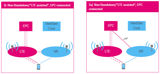
Figure 7. Options 3 and 3a, EN-DC on the EPC. The only difference is where the NR user plane meets the core. It passes through the LTE node in Option 3, and it has its own S1-U in Option 3a.
< Option 4 and Option 4a >
These two are Option 3 with the roles exchanged. The core in use is the NextGen Core, and this time the EPC box is the one drawn without a line. NR holds the connection to the core, and LTE is the secondary radio beside it. Option 4a adds a line labelled 1A-LIKE from the NextGen Core to the LTE radio, so LTE gets a path of its own.
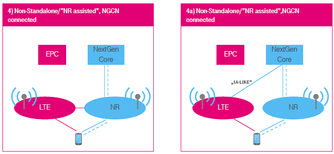
Figure 8. Options 4 and 4a, NE-DC on the 5G core. The roles are reversed from Option 3, so the gNB is the master and LTE is the secondary node.
< Option 5 and Option 6 >
Neither picture has two radios, so neither one is dual connectivity. Option 5 draws the existing LTE radio with a line to the NextGen Core, and nothing else. Option 6 draws an NR radio with a line to the EPC. The second picture is the one that was never built.
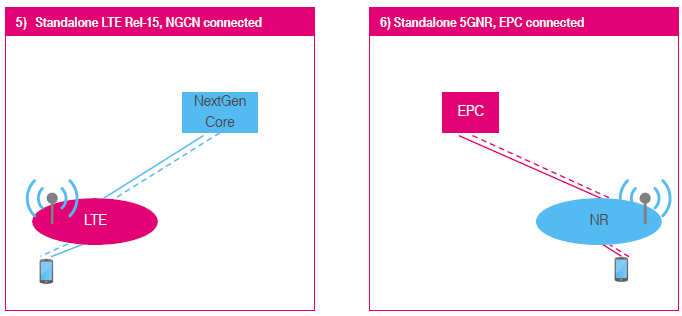
Figure 9. Options 5 and 6, both standalone. Option 5 puts the existing LTE radio on the 5G core. Option 6 puts NR on the EPC, and it was never pursued.
< Option 7 and Option 7a >
Set these beside Options 3 and 3a and only the core box changes. LTE still holds the connection, and NR is still the secondary radio. The difference is that the line from LTE now runs to the NextGen Core instead of the EPC. Option 7a adds the 1A-LIKE line from that core to the NR radio.
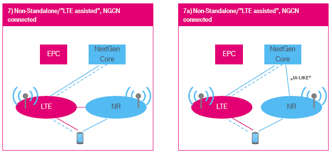
Figure 10. Options 7 and 7a, NGEN-DC. This is Option 3 with the core replaced, so an operator that starts at Option 3 can reach it by upgrading the core rather than the radio.
< Option 8 and Option 8a >
These are the mirror of Options 7 and 7a, drawn on the EPC instead. NR holds the connection to the EPC, and the LTE radio is drawn beside it as the secondary. Option 8a adds the 1A-LIKE line from the EPC to the LTE radio. Neither one was specified, so the pictures are a record of what was considered and rejected.
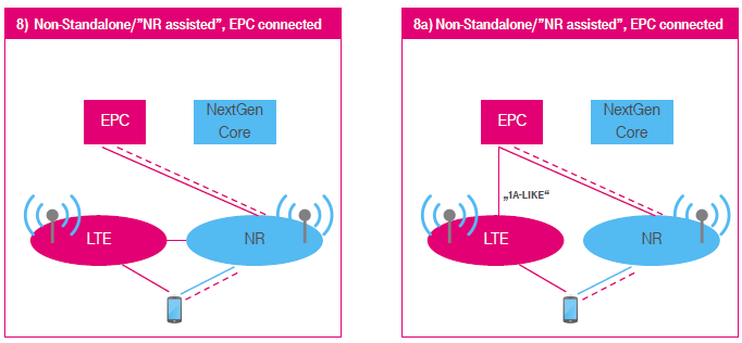
Figure 11. Options 8 and 8a. NR is the master and the core is still the EPC. Like Option 6, this combination was studied and never pursued.
What do the deployment option numbers mean?
The figures above name the options and never define them, and the numbering is not self-explanatory. Two questions settle every one of them. Which core network is the radio connected to, and which node is the master? I kept re-deriving the answer from the pictures until I wrote the two questions down. Everything else in the option list follows from those two. The table below answers both questions for every option in one place. Two further points follow from it, and neither is visible in the pictures. An option number says nothing about the frequency band or the cell layout. It also says nothing about which bearer types are configured, because that is a separate choice made per bearer.
An option with a single number is standalone, so one radio technology talks to one core. An option with two numbers is dual connectivity, and the master node is the one that holds the RRC connection and the control plane. The letter suffix does not change either of those. It changes only where the secondary node's user plane meets the core.
|
Option |
Core |
Master node |
Secondary node |
3GPP name |
Status |
|
1 |
EPC |
eNB |
|
|
in service before 5G |
|
2 |
5GC |
gNB |
|
NR SA |
specified and deployed |
|
3 / 3a / 3x |
EPC |
eNB |
en-gNB |
EN-DC |
specified, and the first commercial 5G |
|
4 / 4a |
5GC |
gNB |
ng-eNB |
NE-DC |
specified |
|
5 |
5GC |
ng-eNB |
|
|
specified |
|
6 |
EPC |
gNB |
|
|
studied, not pursued |
|
7 / 7a / 7x |
5GC |
ng-eNB |
gNB |
NGEN-DC |
specified |
|
8 / 8a |
EPC |
gNB |
eNB |
|
studied, not pursued |
The suffixes are the part most often quoted without explanation, so they need a definition of their own. A plain number means the secondary node has no direct user plane to the core, so its traffic passes through the master node. An a suffix means the secondary node has its own user plane connection to the core. That is the "1A" line drawn in Figure 7, and the "1A-LIKE" line drawn in Figures 8 and 10. An x suffix is not in RP-161266 at all. It came from the industry discussion afterwards, and it means a split bearer whose PDCP entity sits in the gNB.
Two questions define every option : Which core is the radio attached to, and which node is the master. The option number carries no other information.Options 6 and 8 were never pursued : Both attach NR to the EPC with no LTE node as master. The EPC brings none of the 5G core capability, and NR on it still needs new interworking, so neither option was specified.The a suffix is a transport choice, not an architecture : It moves the secondary node's user plane off the master node and onto its own interface to the core. The master node still owns the control plane.The x suffix is industry shorthand : 3GPP specifies the bearer types rather than the letters. Option 3x is the EN-DC split bearer with PDCP in the gNB, and it is the one that was deployed.The figures use pre-Rel-15 names : NextGen Core is the 5G core, and eLTE eNB is the ng-eNB. The pictures were drawn before the names were settled.
How do the TR 38.804 cases map onto the RP-161266 options?
This page shows both representations, and they number the same deployments differently. That is a real source of confusion, because Case 4 and Option 3 describe one network. The mapping is one to one everywhere except in a single place, and the table below gives it. The two documents differ because they were written for different purposes. TR 38.804 is a study on radio interface protocol aspects, so it sorts the cases by which node terminates the control plane. RP-161266 is an architecture proposal written for the migration debate, so it sorts them by the order an operator would deploy them. Neither ordering is wrong. They answer different questions, and the industry settled on quoting the second one.
TR 38.804 sorts the cases by which node is the master, which is why Figure 4 and Figure 5 are two separate trees. RP-161266 sorts them by option number instead. The one case with no option number is Case 3, because RP-161266 never drew NR with NR.
|
TR 38.804 |
Master |
Core |
RP-161266 |
MR-DC name |
|
Case 1 |
gNB only |
5GC |
Option 2 |
standalone |
|
Case 2 |
gNB |
5GC |
Option 4 / 4a |
NE-DC |
|
Case 3 |
gNB |
5GC |
no option number |
NR-DC |
|
Case 4 |
eNB |
EPC |
Option 3 / 3a |
EN-DC |
|
Case 5 |
ng-eNB only |
5GC |
Option 5 |
standalone |
|
Case 6 |
ng-eNB |
5GC |
Option 7 / 7a |
NGEN-DC |
Case 4 and Option 3 are the same network : An LTE master on the EPC with an NR secondary node. This is the deployment the rest of the industry calls NSA.Case 3 has no option number : NR with NR is not in RP-161266. It was specified later as NR-DC, and it only applies once the operator is already standalone.The MR-DC names are the durable ones : EN-DC, NGEN-DC and NE-DC are defined in TS 37.340 and they say which radio is master and which core is behind it. The option numbers say the same thing less clearly.
Why did almost every operator start with Option 3x?
Twelve options were drawn, and the industry converged on one of them. I read that convergence as a commercial decision more than a technical one. Option 3x is the only choice that lets an operator sell 5G without replacing anything it already runs. That claim needs a date attached to it. It describes the launches from 2019 to about 2021, when no 5G core was in commercial service. Standalone launches followed later, and a few operators went to Option 2 directly. The reasoning below is therefore about the starting point, and not about where a network stays.
The first reason is the core network. Option 3 keeps the EPC, so no 5G core has to be deployed, integrated or paid for at launch. The second reason is coverage. The LTE cell holds the control plane, so a UE that loses NR does not lose the connection. That matters at 3.5 GHz and it matters far more at mmWave. The third reason is voice. With LTE as the master the call stays on VoLTE, and VoNR does not have to work before launch.
The remaining question is why 3x rather than 3 or 3a. In Option 3 the whole user plane passes through the eNB. The LTE node then has to carry the NR throughput on its backhaul and in its PDCP. The slower node becomes the limit on the faster one. In Option 3a the split happens in the core, so a single bearer cannot use both radios and there is no aggregation gain. Option 3x puts the PDCP entity in the gNB. The higher capacity node then decides, packet by packet, which leg to send each packet down.
Option 3 is an upgrade, not a rebuild : The EPC, the LTE coverage layer and VoLTE all stay in place. Only the NR radio is new.The anchor is what makes patchy NR usable : LTE holds the control plane, so losing NR degrades the throughput rather than dropping the connection.3x moves the bottleneck to the fast node : With PDCP in the gNB, the LTE backhaul no longer has to carry the NR user plane.Option 7 is the cheap next step : It is Option 3 with the core replaced, so the radio investment is preserved. Figure 10 and Figure 7 differ only in the core.Option 2 is the destination, not the start : Standalone NR needs a 5G core, full NR coverage and VoNR. Each of those is a separate programme, which is why the intermediate options exist at all.
Overall Radio Network Architecture
The architecture question is smaller than it looks. NG-RAN keeps the shape of E-UTRAN, with base stations connected to each other and to a core. Most of what changed is the names of the interfaces, and the split of the core into separate control and user plane functions. Three renames carry most of the difference. X2 between eNBs becomes Xn between gNBs. S1-MME to the MME becomes NG-C to the AMF. S1-U to the S-GW becomes NG-U to the UPF. The one structural change sits in the core rather than in the radio. The MME and the S-GW were specified together as one pair of nodes. The AMF and the UPF are separate functions, and a network can scale and place each of them independently.
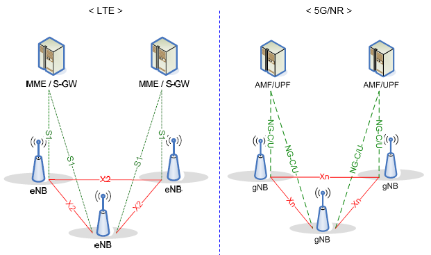
Figure 12. The interfaces were renamed rather than redesigned. X2 between eNBs becomes Xn between gNBs, and S1 to the MME and S-GW becomes NG-C and NG-U to the AMF and UPF.
Bearer Architecture for Dual Connectivity between LTE and NR
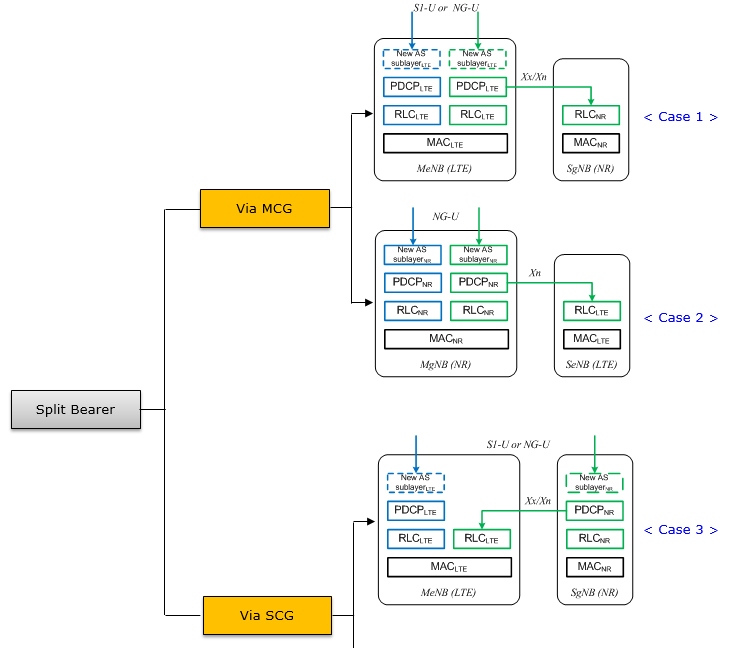
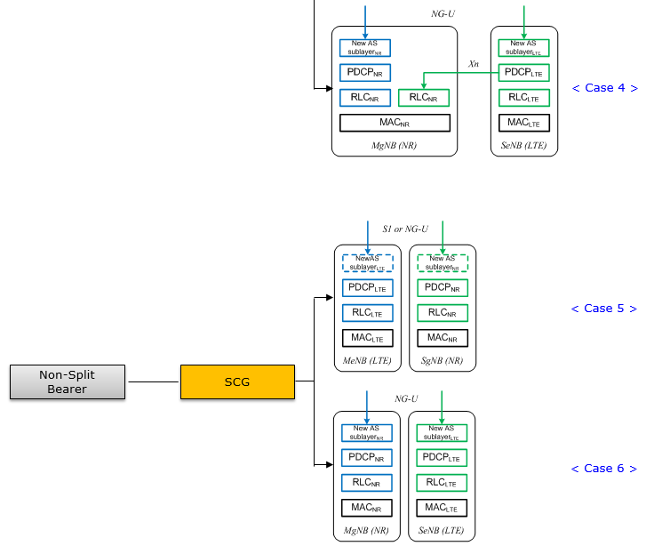
Dual connectivity is decided per bearer, and not per cell. A UE in EN-DC does not send every bearer over both nodes. Each bearer is configured as one of a small number of types, and the type decides which node terminates PDCP. That choice also decides whether the traffic can be split across the two legs at all. Three bearer types cover every case in the figures. An MCG bearer terminates entirely in the master node. An SCG bearer terminates entirely in the secondary node. A split bearer has one PDCP entity and two RLC legs, so a single flow can use both radios at once. The figures sort these by which node holds the PDCP entity, and by whether a second leg exists at all. Case 3 is the one that matters most in practice. It is the split bearer with PDCP in the secondary NR node, and that is the architecture the industry calls Option 3x.
Reference
TR 38.804 and RP-161266 are the two documents that supplied the figures on this page. The two number the same deployments differently, and that is the reason the mapping section above exists. TS 37.340 is the document to read next, because it is where the MR-DC bearer types and the master and secondary roles are specified. The two WirelessMoves articles cover the migration debate at a level of business detail this page does not attempt.
[1] 3GPP TR 38.804 V1.0.0 (2017-03) Study on New Radio Access Technology;Radio Interface Protocol Aspects
[2] 3GPP TR 36.842 V12.0.0 (2013-12) Study on Small Cell enhancements for E-UTRA and E-UTRAN; Higher layer aspects
[3] RP-161266 : 5G architecture options full set
[4] WirelessMoves : 5G Beyond Option 3 Pt. 1
[5] WirelessMoves : 5G Beyond Option 3 Pt. 2
[6] 3GPP TS 37.340 : Multi-connectivity; Overall description; Stage-2
[7] 3GPP TS 38.300 : NR; NR and NG-RAN Overall description; Stage-2