|
CORESET 0 and SIB1 Scheduling in Detail
Type 0 PDCCH Common Search Space is a subset of NR PDCCH Search Space that is dedicated to transmit the PDCCH for SI message (SIB). Therefore, what I am going to explain on this page is related to transmitting/decoding SIB1 in SA(Standalone) mode.
- Why we need a special procedure ?
- Basic Questions
- RRC Parameters defining CORESET 0
- CORESET 0 Position in Time Domain
- CORESET 0 Position in Frequency Domain
- Example 01 > SSB/PDCCH SCS = {30,30}, Index 10 in Table 13-4
- Example 02 > SSB/PDCCH SCS = {30,30}, Index 11 in Table 13-4
- Example 03 > SSB/PDCCH SCS = {30,30}, Index 12 in Table 13-4
- CORESET 0 Transmission Slots
- Example 01 > SSB/PDCCH SCS = {30,30}, SSB Index = 0, Table 13-11 = 4
- Example 02 > n0 , SSB/PDCCH SCS = {30,30}, SSB Index = 0, Table 13-11
- Example 03 > SFNc , SSB/PDCCH SCS = {30,30}, SSB Index = 0, Table 13-11
- Example 04 > SFNc for SSB/PDCCH SCS = {30,30}, Varrying SSB index, O/N Index in Table 13-11 = 4
- Example 05 > n0 for SSB/PDCCH SCS = {30,30}, Varrying SSB index, O/N Index in Table 13-11 = 4
- CORESET 0 Aggregation Level
- Whole Table
- Visual Summary
- Tips for CORESET0 Index Selection
- Time Domain Resource Allocation for SIB1 PDSCH
- Get the Test Procedure and Log / Amarisoft TechAcademy
Why we need a special procedure ?
SIB1 is carried by a PDSCH like any other user data (or other Over The Air message : OTA). Then, why we need a special algorithm for transmitting and decoding a PDSCH carrying SIB1 ?
Before answering the question, let's briefly summarize a mechanism in which other user data or downlink OTA message is scheduled and decoded. It goes as follows.
i) network defines a specific physical resources for transmitting DCI (CORESET)
ii) network defines a specific set of candidate physical resources that UE has to monitor (Search Space) to find scheduling information
iii) network defines a list of symbol allocation (TimeDomainResourceAllocation) for PDSCH
iv) Network notifies UE of all of these configuration information via RRC message (like SIB1, RRCSetup or RRCReconfiguration)
v) When the network want to send a specific PDSCH, it sends a DCI and transmits PDSCH as scheduled in the DCI.
The keyword for this process is RRC message. In case of user data or other OTA message, PDSCH is transmitted after all the detailed configuration information is informed to UE. But SIB1 transmission/decoding should happen before any RRC message is delivered to UE. The only RRC message delivered to UE before SIB1 transmission is MIB message. As you know, MIB can carry only a handful of information.. not enough space to carry all the detailed information mentioned above. Then how can UE figure out all the detailed information at this point ? A common technique to handle this kind of situation (i.e, letting UE know of the long/detailed information without relying on a lengthy RRC message) is to use some predefined table (predefined configuration) and algorithm known to both UE and NW by the specification. This is the basic idea of transmitting and decoding SIB1 in NR.
3GPP defined many of predefined tables and algorithms to process it and a few information elements in MIB specifies which of the predefined table should be used.
Basic Questions.
This process is very complicated and confusing. It would be good idea to have a set of clear questions in your mind. Followings are my own version of the questions that I have before reading the details.
How Can we figure out physical resources for the CORESET ? : How can we figure out how many RBs and OFDM symbols are assigned for the CORESET ? you can figure this out from controlResourceSetZero parameter expained in RRC Parameters defining CORESET 0 and CORESET 0 position in frequency domain. This plays the same role as coreset definition parameters in RRC message that is explained here.How Can we figure out which OFDM symbols to monitor to search the CORESET ? : You can figure it out from from searchSpaceZero parameter expained in RRC Parameters defining CORESET 0. More specifically, the first symbol index in table 13-11,13-12,13-13,13-14 tells you the starting symbol of the search space. This plays similar role as monitoringSymbolsWithinSlot as explained here.How Can we figure out on which slots the CORESET is transmitted ? : You can figure it out from searchSpaceZero parameter as explained in CORESET 0 transmission slot section.
RRC Parameters defining CORESET 0
The Common Search Space is defined in 38.213 - section 13. This is long / complicated process. I will take some time for me to digest the process and update this page. One of the key parameter defining the common search space is MIB.pdcchConfigSIB1 (this corresponds to RMSI-PDCCH-Config defined in 38.213 - section 13 as stated below)
If a UE determines that a control resource set for Type0-PDCCH common search space is present, as described in Subclause 4.1, the UE determines a number of consecutive resource blocks and a number of consecutive symbols for the control resource set of the Type0-PDCCH common search space from the four most significant bits of RMSI-PDCCH-Config as described in Tables 13-1 through 13-10 and determines PDCCH monitoring occasions from the four least significant bits of RMSI-PDCCH-Config, included in MasterInformationBlock, as described in Tables 13-11 through 13-15
My translation for this statement is what I want to describe in this page.
The CORESET and PDCCH Occasion(time domain location for the PDCCH) are determined by a MIB parameter and many predefined tables as shown below.
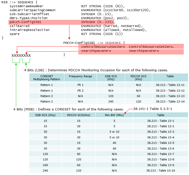
NOTE : SCS stands for SubCarrier Spacing
NOTE 1 : You need to figure out which of the PDCCH Monitoring Occassion table (CORESET Multiplexing Pattern) to be used, by looking at FR or SSB SCS / PDCCH SCS which is given to you.
NOTE 2 : You need to figure out which of CORESET defintion table to be used, by looking at FR or SSB SCS / PDCCH SCS which is given to you
Since there are many tables associated with these two parameters, the size of permutations of these two parameters is huge as summarized in the following table.
|
38.213-Table |
Index Range |
Multiplex Pattern |
38.213-Table |
Index Range |
Permutations |
|
0~14 |
1 |
0~15 |
240 |
||
|
0~13 |
1 |
0~15 |
224 |
||
|
0~8 |
1 |
0~15 |
144 |
||
|
0~15 |
1 |
0~15 |
256 |
||
|
0~8 |
1 |
0~15 |
144 |
||
|
0~9 |
1 |
0~15 |
160 |
||
|
0~7 |
1 |
0~13 |
112 |
||
|
8~11 |
2 |
0 |
4 |
||
|
0~3 |
1 |
0~13 |
14 |
||
|
4~7 |
3 |
0 |
4 |
||
|
0~3 |
1 |
0~14 |
56 |
||
|
0~3 |
1 |
0~14 |
56 |
||
|
4~7 |
2 |
0 |
4 |
||
|
Total Permutations |
1,418 |
||||
Example 01 > pdcch-ConfigSIB1 = 0 (INTEGER). SSB SCS = 30 Khz, PDCCH SCS = 30 Khz
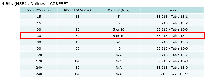
With the given condition of SSB SCS = 30 Khz, PDCCH SCS = 30 Khz and assume that the band is n78. From SSB SCS and PDCCH SCS, we can find two candidates Table 13-4 and Table 13-6. To find which of the two candidate to choose, we need additional information Min BW. This min BW varies depending NR band and the channel BW that are supported by the band. This is defined in 38.101-1 Table 5.3.5-1. From this table, you would notice the minimum Bandwidth that n78 support is 10Mhz.
In conclusion, you would know the CORESET table we need to look into is 38.213-Table 13-4.
With the conclusion above and MSB 4 bit of pdcch-ConfigSIB1 = 0000, we get to the conclusion that we need to use the CORESET configuration as shown below. From the values given in this table, you may visualize the CORESET as explained in this page.
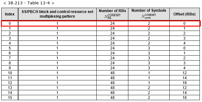
From the conclusion above, we got a parameter that is necessry for the next step. It is 'SS/PBCH block and control resource set multiplexing pattern'. The multiplexing pattern for this case is '1'. Also from the fact that SSB SCS is 30 Khz, we can figure out that the frequency range is FR1 (Sub 6).
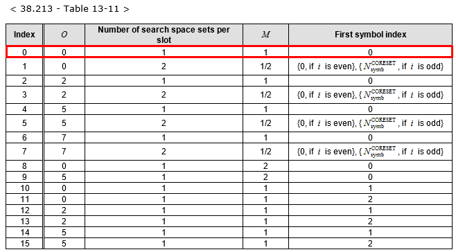
With all the information we got above (i.e, multiplexing patter = 1, frequency range = FR1), we can get to the conclusion that we need to look into 38.213-Table 13-11. And with the fact that LSB 4 bit of pdcch-ConfigSIB1 = 0000, we get to the conclusion that search space for PDCCH is defined as follows.
CORESET 0 Position in Time Domain
In regular CORESET (i.e, CORESETs other than CORESET 0), the time domain position is determined by the following two RRC IE(information element).
- SearchSpace -> monitoringSymbolsWithinSlot : Specifies the start position of the coreset
- ControlResourceSet -> duration : Specifies the symbol length of the coreset.
In case of CORESET 0, these two parameters are specified in predefined table as shown in previous sections.
- SearchSpace -> monitoringSymbolsWithinSlot : 'First symbol index' column from table 13-11 and onwards
- ControlResourceSet -> duration : 'Number of symbols' column from table 13-1 through table 13-11.
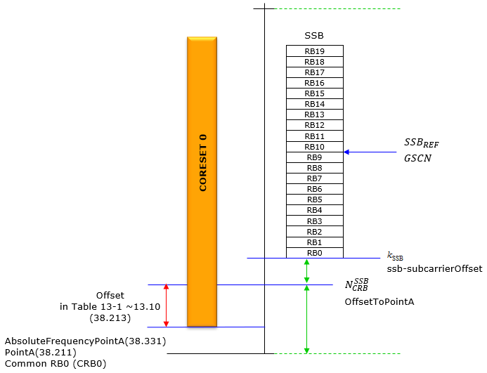
CORESET 0 Position in Frequency Domain
The CORESET 0 Location in frequency domain is determined based on following statement in 38.213.
- k_ssb : always 15 Khz subcarrier spacing for FR1, 60 Khz subcarrier spacing for FR2 regardless of SSB subcarrier spacing.
- OffsetToPointA : the unit of this parameter is number of RB. Subcarrier spacing within this RB is always 15 Khz subcarrier spacing for FR1, 60 Khz subcarrier spacing for FR2 regardless of SSB subcarrier spacing.
- SSB Subcarrier Spacing : this varies depending on subCarrierSpacingCommon value in MIB. It can be summarized as follows.
- When subCarrierSpacingCommon = scs15or60,
- Subcarrier Spacing for FR1 = 15 Khz
- Subcarrier Spacing for FR2 = 60 Khz
- When subCarrierSpacingCommon = scs30or120,
- Subcarrier Spacing for FR1 = 30 Khz
- Subcarrier Spacing for FR2 = 120 Khz
The offset in Tables 13-1 through 13-10 is defined with respect to the SCS of the CORESET for Type0-PDCCH CSS set, provided by subCarrierSpacingCommon, from the smallest RB index of the CORESET for Type0-PDCCH CSS set to the smallest RB index of the common RB overlapping with the first RB of the corresponding SS/PBCH block
Based on this statement, I illustrate the CORESET 0 position as shown below.
- Simulation on where to place coreset 0 : WebSim note in Sharetechnote
- 5G NR frequency band : https://www.sqimway.com/nr_band.php
- NR Reference Point A : https://www.sqimway.com/nr_refA.php
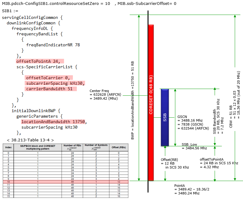
Example 01 > SSB/PDCCH SCS = {30,30}, Index 10 in Table 13-4
Following illustration is based on a SA log from Amarisoft. GSCN and Center Frequency is set as hardware configuration of the equipment.
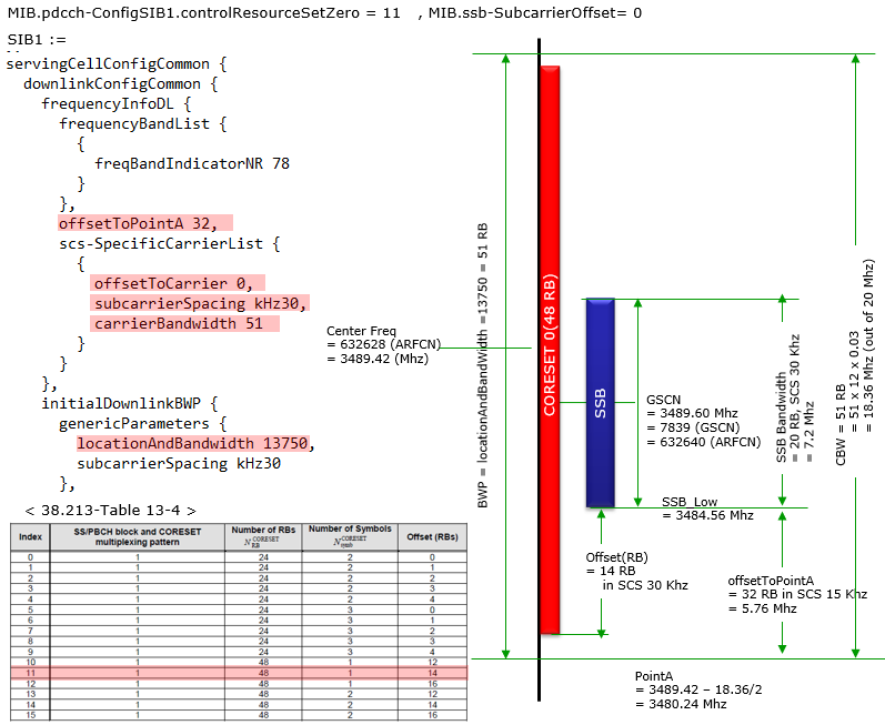
Example 02 > SSB/PDCCH SCS = {30,30}, Index 11 in Table 13-4
Following illustration is based on a SA log from Amarisoft. GSCN and Center Frequency is set as hardware configuration of the equipment.
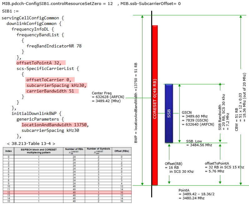
Example 03 > SSB/PDCCH SCS = {30,30}, Index 12 in Table 13-4
Following illustration is based on a SA log from Amarisoft. GSCN and Center Frequency is set as hardware configuration of the equipment.
CORESET 0 Transmission Slots
The transmission and monitoring is defined by the 3GPP TS 38.213 - Section 13. This process involves determining the timing and slot positions for CORESET 0 transmission in relation to theSSB blocks, using multiplexing pattern. It ensures that the UE can efficiently monitor the PDCCH in the correct slots and symbols, based on parameters like slot offsets, scaling factors, and numerology, enabling successful initial access and synchronization with the 5G network.
The overall logic of determining the Coreset 0 transmission is illustrated as below
![]()
![]()
Let’s break down the process.
PDCCH monitoring for Type0-PDCCH CSS (Common Search Space) set is associated with SS/PBCH blocks and CORESET multiplexing pattern. The key points are:
- CORESET 0 Transmission Timing:
- CORESET 0 is transmitted in even frames when [(O · 2μ + ⌊i · M⌋) / Nslotframe,μ] mod 2 = 0.
- CORESET 0 is transmitted in odd frames when [(O · 2μ + ⌊i · M⌋) / Nslotframe,μ] mod 2 = 1.
- Slot Index for Monitoring:
- The slot index n0 where the UE monitors PDCCH is given by:
- n0 = (O · 2μ + ⌊i · M⌋) mod Nslotframe,μ
- The UE monitors two consecutive slots starting from slot n0, i.e., slots n0 and n0 + 1.
The imprtant point of this process (calculation) is to figure out n0. n0represents the starting slot index within a radio frame where the UE begins monitoring the PDCCH for the Type0-PDCCH Common Search Space (CSS) set, which is associated with CORESET 0
Practically, n0 determines the exact timing (in terms of slots) within a radio frame where the UE should look for CORESET 0, which contains the PDCCH. With 38.213 Table 13-11, as an example, for μ = 1 (where Nslotframe,μ = 20), O = 0, and M = 1/2, the values of n0 are calculated as 0, 1, 2, and 3 for SS/PBCH block indices i = 0, 2, 4, 6, respectively. This means the UE monitors slots 0 and 1 for i = 0, slots 1 and 2 for i = 2, and so on. This slot index ensures that the UE aligns its monitoring with the network’s transmission schedule for CORESET 0, which is tied to the SS/PBCH block transmissions.
Example 01 > SSB/PDCCH SCS = {30,30}, SSB Index = 0, Table 13-11 = 4
This example is the case where FR1 and Pattern 1 is used, SSB index is 0 (the first SSB) and the index within the table 13-11 is 4 (This index is configured by the IE SearchSpaceZero in MIB).
According to the calculation shown below, CORESET 0 is scheduled at slot 10 in the radio frame that meets the SFNc criteria.
![]()
According to following calculation, CORESET 0 is scheduled to be every EVEN radio frame. (This determined the radio frame where the SSB is transmitted)
![]()
Example 02 > n0 , SSB/PDCCH SCS = {30,30}, SSB Index = 0, Table 13-11
Followng table lists the calculated n0 for every indexes of Table 13-11. You may try calculating n0 on your own as explained above. Just for practice.
|
index |
O |
M |
n0 |
|
0 |
0 |
1 |
0 |
|
1 |
0 |
1/2 |
0 |
|
2 |
2 |
1 |
4 |
|
3 |
2 |
1/2 |
4 |
|
4 |
5 |
1 |
10 |
|
5 |
5 |
1/2 |
10 |
|
6 |
7 |
1 |
14 |
|
7 |
7 |
1/2 |
14 |
|
8 |
0 |
2 |
0 |
|
9 |
5 |
2 |
10 |
|
10 |
0 |
1 |
0 |
|
11 |
0 |
1 |
0 |
|
12 |
2 |
1 |
4 |
|
13 |
2 |
1 |
4 |
|
14 |
5 |
1 |
10 |
|
15 |
5 |
1 |
10 |
Example 03 > SFNc , SSB/PDCCH SCS = {30,30}, SSB Index = 0, Table 13-11
Followng table lists the calculated SFNc for every indexes of Table 13-11. You may try calculating n0 on your own as explained above. Just for practice.
|
index |
O |
M |
SFNc |
|
0 |
0 |
1 |
0 |
|
1 |
0 |
1/2 |
0 |
|
2 |
2 |
1 |
0 |
|
3 |
2 |
1/2 |
0 |
|
4 |
5 |
1 |
0 |
|
5 |
5 |
1/2 |
0 |
|
6 |
7 |
1 |
0 |
|
7 |
7 |
1/2 |
0 |
|
8 |
0 |
2 |
0 |
|
9 |
5 |
2 |
0 |
|
10 |
0 |
1 |
0 |
|
11 |
0 |
1 |
0 |
|
12 |
2 |
1 |
0 |
|
13 |
2 |
1 |
0 |
|
14 |
5 |
1 |
0 |
|
15 |
5 |
1 |
0 |
Example 04 > SFNc for SSB/PDCCH SCS = {30,30}, Varrying SSB index, O/M Index in Table 13-11 = 4
Following table shows the SFNc for every SSB burst in FR1 assuming that the index in Table 13-11 (i.e, the IE SearchSpaceZero in MIB) is configured to be 4. For practice, try to make table when SearchSpaceZero in MIB is configured to different value.
|
SSB index |
O |
M |
SFNc |
|
0 |
5 |
1 |
0 |
|
1 |
5 |
1 |
0 |
|
2 |
5 |
1 |
0 |
|
3 |
5 |
1 |
0 |
|
4 |
5 |
1 |
0 |
|
5 |
5 |
1 |
0 |
|
6 |
5 |
1 |
0 |
|
7 |
5 |
1 |
0 |
Example 05 : n0 for SSB/PDCCH SCS = {30,30}, Varrying SSB index, O/M Index in Table 13-11 = 4
Following table shows the n0 for every SSB burst in FR1 assuming that the index in Table 13-11 (i.e, the IE SearchSpaceZero in MIB) is configured to be 4. For practice, try to make table when SearchSpaceZero in MIB is configured to different value.
|
SSB index |
O |
M |
n0 |
|
0 |
5 |
1 |
10 |
|
1 |
5 |
1 |
11 |
|
2 |
5 |
1 |
12 |
|
3 |
5 |
1 |
13 |
|
4 |
5 |
1 |
14 |
|
5 |
5 |
1 |
15 |
|
6 |
5 |
1 |
16 |
|
7 |
5 |
1 |
17 |
CORESET 0 Aggregation Level
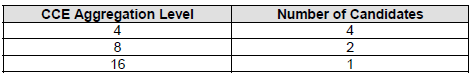
What is the aggregation level that are applicable to CORESET 0 for SIB1 decoding ? I haven't found any explicit statement yet from the specification, but I guess that at least following aggregation levels would be applicable to CORESET 0 as per 38.213 - Section 10.
< 38.213 - Table 10.1-1: CCE aggregation levels and maximum number of PDCCH candidates per CCE aggregation level for CSS sets configured by searchSpaceSIB1 >
Whole Table
All of the following tables are from 38.213 v15.7
Table 13-1: Set of resource blocks and slot symbols of CORESET for Type0-PDCCH search space set when {SS/PBCH block, PDCCH} SCS is {15, 15} kHz for frequency bands with minimum channel bandwidth 5 MHz or 10 MHz
|
Index |
SS/PBCH block and CORESET |
Number of RBs |
Number of Symbols |
Offset (RBs) |
|---|---|---|---|---|
|
0 |
1 |
24 |
2 |
0 |
|
1 |
1 |
24 |
2 |
2 |
|
2 |
1 |
24 |
2 |
4 |
|
3 |
1 |
24 |
3 |
0 |
|
4 |
1 |
24 |
3 |
2 |
|
5 |
1 |
24 |
3 |
4 |
|
6 |
1 |
48 |
1 |
12 |
|
7 |
1 |
48 |
1 |
16 |
|
8 |
1 |
48 |
2 |
12 |
|
9 |
1 |
48 |
2 |
16 |
|
10 |
1 |
48 |
3 |
12 |
|
11 |
1 |
48 |
3 |
16 |
|
12 |
1 |
96 |
1 |
38 |
|
13 |
1 |
96 |
2 |
38 |
|
14 |
1 |
96 |
3 |
38 |
|
15 |
Reserved |
|||
Table 13-2: Set of resource blocks and slot symbols of CORESET for Type0-PDCCH search space set when {SS/PBCH block, PDCCH} SCS is {15, 30} kHz for frequency bands with minimum channel bandwidth 5 MHz or 10 MHz
|
Index |
SS/PBCH block and CORESET |
Number of RBs |
Number of Symbols |
Offset (RBs) |
|---|---|---|---|---|
|
0 |
1 |
24 |
2 |
5 |
|
1 |
1 |
24 |
2 |
6 |
|
2 |
1 |
24 |
2 |
7 |
|
3 |
1 |
24 |
2 |
8 |
|
4 |
1 |
24 |
3 |
5 |
|
5 |
1 |
24 |
3 |
6 |
|
6 |
1 |
24 |
3 |
7 |
|
7 |
1 |
24 |
3 |
8 |
|
8 |
1 |
48 |
1 |
18 |
|
9 |
1 |
48 |
1 |
20 |
|
10 |
1 |
48 |
2 |
18 |
|
11 |
1 |
48 |
2 |
20 |
|
12 |
1 |
48 |
3 |
18 |
|
13 |
1 |
48 |
3 |
20 |
|
14 |
Reserved |
|||
|
15 |
Reserved |
|||
Table 13-3: Set of resource blocks and slot symbols of CORESET for Type0-PDCCH search space set when {SS/PBCH block, PDCCH} SCS is {30, 15} kHz for frequency bands with minimum channel bandwidth 5 MHz or 10 MHz
|
Index |
SS/PBCH block and CORESET |
Number of RBs |
Number of Symbols |
Offset (RBs) |
|---|---|---|---|---|
|
0 |
1 |
48 |
1 |
2 |
|
1 |
1 |
48 |
1 |
6 |
|
2 |
1 |
48 |
2 |
2 |
|
3 |
1 |
48 |
2 |
6 |
|
4 |
1 |
48 |
3 |
2 |
|
5 |
1 |
48 |
3 |
6 |
|
6 |
1 |
96 |
1 |
28 |
|
7 |
1 |
96 |
2 |
28 |
|
8 |
1 |
96 |
3 |
28 |
|
9 |
Reserved |
|||
|
10 |
Reserved |
|||
|
11 |
Reserved |
|||
|
12 |
Reserved |
|||
|
13 |
Reserved |
|||
|
14 |
Reserved |
|||
|
15 |
Reserved |
|||
Table 13-4: Set of resource blocks and slot symbols of CORESET for Type0-PDCCH search space set when {SS/PBCH block, PDCCH} SCS is {30, 30} kHz for frequency bands with minimum channel bandwidth 5 MHz or 10 MHz
|
Index |
SS/PBCH block and CORESET |
Number of RBs |
Number of Symbols |
Offset (RBs) |
|---|---|---|---|---|
|
0 |
1 |
24 |
2 |
0 |
|
1 |
1 |
24 |
2 |
1 |
|
2 |
1 |
24 |
2 |
2 |
|
3 |
1 |
24 |
2 |
3 |
|
4 |
1 |
24 |
2 |
4 |
|
5 |
1 |
24 |
3 |
0 |
|
6 |
1 |
24 |
3 |
1 |
|
7 |
1 |
24 |
3 |
2 |
|
8 |
1 |
24 |
3 |
3 |
|
9 |
1 |
24 |
3 |
4 |
|
10 |
1 |
48 |
1 |
12 |
|
11 |
1 |
48 |
1 |
14 |
|
12 |
1 |
48 |
1 |
16 |
|
13 |
1 |
48 |
2 |
12 |
|
14 |
1 |
48 |
2 |
14 |
|
15 |
1 |
48 |
2 |
16 |
Table 13-5: Set of resource blocks and slot symbols of CORESET for Type0-PDCCH search space set when {SS/PBCH block, PDCCH} SCS is {30, 15} kHz for frequency bands with minimum channel bandwidth 40MHz
|
Index |
SS/PBCH block and CORESET |
Number of RBs |
Number of Symbols |
Offset (RBs) |
|---|---|---|---|---|
|
0 |
1 |
48 |
1 |
4 |
|
1 |
1 |
48 |
2 |
4 |
|
2 |
1 |
48 |
3 |
4 |
|
3 |
1 |
96 |
1 |
0 |
|
4 |
1 |
96 |
1 |
56 |
|
5 |
1 |
96 |
2 |
0 |
|
6 |
1 |
96 |
2 |
56 |
|
7 |
1 |
96 |
3 |
0 |
|
8 |
1 |
96 |
3 |
56 |
|
9 |
Reserved |
|||
|
10 |
Reserved |
|||
|
11 |
Reserved |
|||
|
12 |
Reserved |
|||
|
13 |
Reserved |
|||
|
14 |
Reserved |
|||
|
15 |
Reserved |
|||
Table 13-6: Set of resource blocks and slot symbols of CORESET for Type0-PDCCH search space set when {SS/PBCH block, PDCCH} SCS is {30, 30} kHz for frequency bands with minimum channel bandwidth 40MHz
|
Index |
SS/PBCH block and CORESET |
Number of RBs |
Number of Symbols |
Offset (RBs) |
|---|---|---|---|---|
|
0 |
1 |
24 |
2 |
0 |
|
1 |
1 |
24 |
2 |
4 |
|
2 |
1 |
24 |
3 |
0 |
|
3 |
1 |
24 |
3 |
4 |
|
4 |
1 |
48 |
1 |
0 |
|
5 |
1 |
48 |
1 |
28 |
|
6 |
1 |
48 |
2 |
0 |
|
7 |
1 |
48 |
2 |
28 |
|
8 |
1 |
48 |
3 |
0 |
|
9 |
1 |
48 |
3 |
28 |
|
10 |
Reserved |
|||
|
11 |
Reserved |
|||
|
12 |
Reserved |
|||
|
13 |
Reserved |
|||
|
14 |
Reserved |
|||
|
15 |
Reserved |
|||
Table 13-7: Set of resource blocks and slot symbols of CORESET for Type0-PDCCH search space set when {SS/PBCH block, PDCCH} SCS is {120, 60} kHz
|
Index |
SS/PBCH block and CORESET |
Number of RBs |
Number of |
Offset (RBs) |
|---|---|---|---|---|
|
0 |
1 |
48 |
1 |
0 |
|
1 |
1 |
48 |
1 |
8 |
|
2 |
1 |
48 |
2 |
0 |
|
3 |
1 |
48 |
2 |
8 |
|
4 |
1 |
48 |
3 |
0 |
|
5 |
1 |
48 |
3 |
8 |
|
6 |
1 |
96 |
1 |
28 |
|
7 |
1 |
96 |
2 |
28 |
|
8 |
2 |
48 |
1 |
-41 if kSSB = 0 |
|
9 |
2 |
48 |
1 |
49 |
|
10 |
2 |
96 |
1 |
-41 if kSSB = 0 |
|
11 |
2 |
96 |
1 |
97 |
|
12 |
Reserved |
|||
|
13 |
Reserved |
|||
|
14 |
Reserved |
|||
|
15 |
Reserved |
|||
Table 13-8: Set of resource blocks and slot symbols of CORESET for Type0-PDCCH search space set when {SS/PBCH block, PDCCH} SCS is {120, 120} kHz
|
Index |
SS/PBCH block and CORESET |
Number of RBs |
Number of |
Offset (RBs) |
|---|---|---|---|---|
|
0 |
1 |
24 |
2 |
0 |
|
1 |
1 |
24 |
2 |
4 |
|
2 |
1 |
48 |
1 |
14 |
|
3 |
1 |
48 |
2 |
14 |
|
4 |
3 |
24 |
2 |
-20 if kSSB = 0 |
|
5 |
3 |
24 |
2 |
24 |
|
6 |
3 |
48 |
2 |
-20 if kSSB = 0 |
|
7 |
3 |
48 |
2 |
48 |
|
8 |
Reserved |
|||
|
9 |
Reserved |
|||
|
10 |
Reserved |
|||
|
11 |
Reserved |
|||
|
12 |
Reserved |
|||
|
13 |
Reserved |
|||
|
14 |
Reserved |
|||
|
15 |
Reserved |
|||
Table 13-9: Set of resource blocks and slot symbols of CORESET for Type0-PDCCH search space set when {SS/PBCH block, PDCCH} SCS is {240, 60} kHz
|
Index |
SS/PBCH block and CORESET |
Number of RBs |
Number of Symbols |
Offset (RBs) |
|---|---|---|---|---|
|
0 |
1 |
96 |
1 |
0 |
|
1 |
1 |
96 |
1 |
16 |
|
2 |
1 |
96 |
2 |
0 |
|
3 |
1 |
96 |
2 |
16 |
|
4 |
Reserved |
|||
|
5 |
Reserved |
|||
|
6 |
Reserved |
|||
|
7 |
Reserved |
|||
|
8 |
Reserved |
|||
|
9 |
Reserved |
|||
|
10 |
Reserved |
|||
|
11 |
Reserved |
|||
|
12 |
Reserved |
|||
|
13 |
Reserved |
|||
|
14 |
Reserved |
|||
|
15 |
Reserved |
|||
Table 13-10: Set of resource blocks and slot symbols of CORESET for Type0-PDCCH search spaceset when {SS/PBCH block, PDCCH} SCS is {240, 120} kHz
|
Index |
SS/PBCH block and CORESET |
Number of RBs |
Number of |
Offset (RBs) |
|---|---|---|---|---|
|
0 |
1 |
48 |
1 |
0 |
|
1 |
1 |
48 |
1 |
8 |
|
2 |
1 |
48 |
2 |
0 |
|
3 |
1 |
48 |
2 |
8 |
|
4 |
2 |
24 |
1 |
-41 if kSSB = 0 |
|
5 |
2 |
24 |
1 |
25 |
|
6 |
2 |
48 |
1 |
-41 if kSSB = 0 |
|
7 |
2 |
48 |
1 |
49 |
|
8 |
Reserved |
|||
|
9 |
Reserved |
|||
|
10 |
Reserved |
|||
|
11 |
Reserved |
|||
|
12 |
Reserved |
|||
|
13 |
Reserved |
|||
|
14 |
Reserved |
|||
|
15 |
Reserved |
|||
Table 13-11: Parameters for PDCCH monitoring occasions for Type0-PDCCH CSS set - SS/PBCH block and CORESET multiplexing pattern 1 and FR1
|
Index |
O |
Number of search space sets per |
M |
First symbol index |
|---|---|---|---|---|
|
0 |
0 |
1 |
1 |
0 |
|
1 |
0 |
2 |
1/2 |
{0, if i is even}, {CORESETNsymb, if i is odd} |
|
2 |
2 |
1 |
1 |
0 |
|
3 |
2 |
2 |
1/2 |
{0, if i is even}, {CORESETNsymb, if i is odd} |
|
4 |
5 |
1 |
1 |
0 |
|
5 |
5 |
2 |
1/2 |
{0, if i is even}, {CORESETNsymb, if i is odd} |
|
6 |
7 |
1 |
1 |
0 |
|
7 |
7 |
2 |
1/2 |
{0, if i is even}, {CORESETNsymb, if i is odd} |
|
8 |
0 |
1 |
2 |
0 |
|
9 |
5 |
1 |
2 |
0 |
|
10 |
0 |
1 |
1 |
1 |
|
11 |
0 |
1 |
1 |
2 |
|
12 |
2 |
1 |
1 |
1 |
|
13 |
2 |
1 |
1 |
2 |
|
14 |
5 |
1 |
1 |
1 |
|
15 |
5 |
1 |
1 |
2 |
Table 13-12: Parameters for PDCCH monitoring occasions for Type0-PDCCH CSS set - SS/PBCH block and CORESET multiplexing pattern 1 and FR2
|
Index |
O |
Number of search space sets per |
M |
First symbol index |
|---|---|---|---|---|
|
0 |
0 |
1 |
1 |
0 |
|
1 |
0 |
2 |
1/2 |
{0, if i is even}, {7, if i is odd} |
|
2 |
2.5 |
1 |
1 |
0 |
|
3 |
2.5 |
2 |
1/2 |
{0, if i is even}, {7, if i is odd} |
|
4 |
5 |
1 |
1 |
0 |
|
5 |
5 |
2 |
1/2 |
{0, if i is even}, {7, if i is odd} |
|
6 |
0 |
2 |
1/2 |
{0, if i is even}, {CORESETNsymb, if i is odd} |
|
7 |
2.5 |
2 |
1/2 |
{0, if i is even}, {CORESETNsymb, if i is odd} |
|
8 |
5 |
2 |
1/2 |
{0, if i is even}, {CORESETNsymb, if i is odd} |
|
9 |
7.5 |
1 |
1 |
0 |
|
10 |
7.5 |
2 |
1/2 |
{0, if i is even}, {7, if i is odd} |
|
11 |
7.5 |
2 |
1/2 |
{0, if i is even}, {CORESETNsymb, if i is odd} |
|
12 |
0 |
1 |
2 |
0 |
|
13 |
5 |
1 |
2 |
0 |
|
14 |
Reserved |
|||
|
15 |
Reserved |
|||
Table 13-13: PDCCH monitoring occasions for Type0-PDCCH CSS set - SS/PBCH block and CORESET multiplexing pattern 2 and {SS/PBCH block, PDCCH} SCS {120, 60} kHz
|
Index |
PDCCH monitoring occasions (SFN and slot number) |
First symbol index |
|---|---|---|
|
0 |
SFNc = SFNSSB,i nc = nSSB,i |
0, 1, 6, 7 for i = 4k, i = 4k + 1, i = 4k + 2, i = 4k + 3 |
|
1 |
Reserved |
|
|
2 |
Reserved |
|
|
3 |
Reserved |
|
|
4 |
Reserved |
|
|
5 |
Reserved |
|
|
6 |
Reserved |
|
|
7 |
Reserved |
|
|
8 |
Reserved |
|
|
9 |
Reserved |
|
|
10 |
Reserved |
|
|
11 |
Reserved |
|
|
12 |
Reserved |
|
|
13 |
Reserved |
|
|
14 |
Reserved |
|
|
15 |
Reserved |
|
Table 13-14: PDCCH monitoring occasions for Type0-PDCCH CSS set - SS/PBCH block and CORESET multiplexing pattern 2 and {SS/PBCH block, PDCCH} SCS {240, 120} kHz
|
Index |
PDCCH monitoring occasions |
First symbol index |
|---|---|---|
|
0 |
SFNc = SFNSSB,i nc = nSSB,i or nc = nSSB,i - 1 |
0, 1, 2, 3, 0, 1 in i = 8k, i = 8k + 1, i = 8k + 2, i = 8k + 3, i = 8k + 6, i = 8k + 7 (nc = nSSB,i) 12, 13 in i = 8k + 4, i = 8k + 5 (nc = nSSB,i - 1) |
|
1 |
Reserved |
|
|
2 |
Reserved |
|
|
3 |
Reserved |
|
|
4 |
Reserved |
|
|
5 |
Reserved |
|
|
6 |
Reserved |
|
|
7 |
Reserved |
|
|
8 |
Reserved |
|
|
9 |
Reserved |
|
|
10 |
Reserved |
|
|
11 |
Reserved |
|
|
12 |
Reserved |
|
|
13 |
Reserved |
|
|
14 |
Reserved |
|
|
15 |
Reserved |
|
Table 13-15: PDCCH monitoring occasions for Type0-PDCCH CSS set - SS/PBCH block and CORESET multiplexing pattern 3 and {SS/PBCH block, PDCCH} SCS {120, 120} kHz
|
Index |
PDCCH monitoring occasions (SFN and slot number) |
First symbol index |
|---|---|---|
|
0 |
SFNc = SFNSSB,i nc = nSSB,i |
4, 8, 2, 6 in i = 4k, i = 4k + 1, i = 4k + 2, i = 4k + 3 |
|
1 |
Reserved |
|
|
2 |
Reserved |
|
|
3 |
Reserved |
|
|
4 |
Reserved |
|
|
5 |
Reserved |
|
|
6 |
Reserved |
|
|
7 |
Reserved |
|
|
8 |
Reserved |
|
|
9 |
Reserved |
|
|
10 |
Reserved |
|
|
11 |
Reserved |
|
|
12 |
Reserved |
|
|
13 |
Reserved |
|
|
14 |
Reserved |
|
|
15 |
Reserved |
|
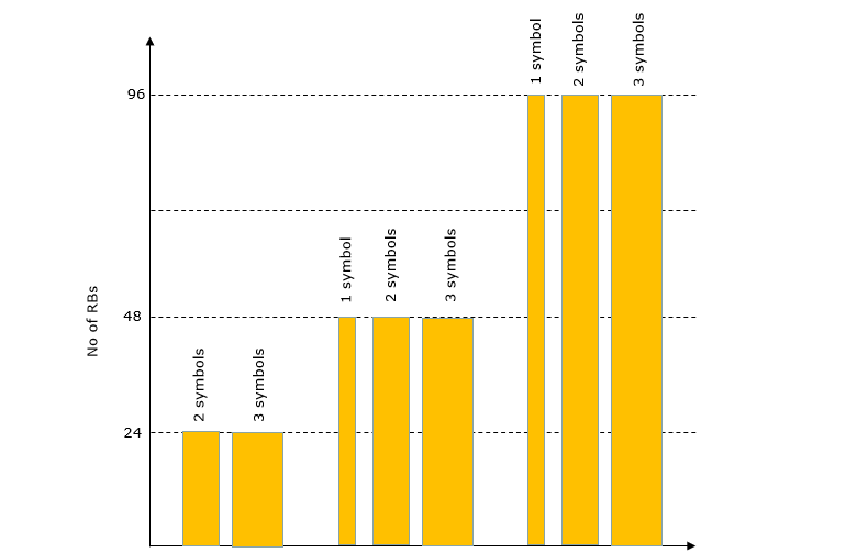
Visual Summary
It would not be easy to get some big picture (intuitive understandings) peneterating through all the tables listed above. To help with this, I tried to get some intuitive image consolidating all the tables as shown below. I hope this helps rather than confusing further :)
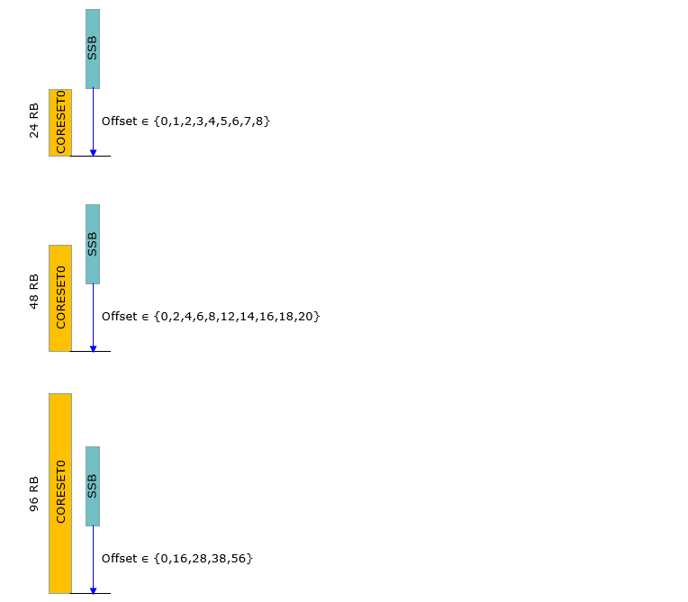
Following is the summary of Number of RB and Symbol Length of Coreset. The frequency span for each case would vary depending on subcarrier spacing.
Following is the summary of possible Offset value from SSB.
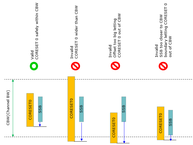
Tips for CORESET0 Index Selection
Even if you got overall understanding on what has been explained above, you may have difficulties with selecting a proper CORESET 0 index if you are asked to pick for a specific case. My tip for picking up a appropriate the index is illustrated below. Just try to remove the index that may fall into the invalid cases shown below and pick one from the remaining indices. It is highly likely that your selection is correct.
Time Domain Resource Allocation for SIB1 PDSCH
Once all the information about CORESET 0 is determined, UE need to figure of PDSCH resource informtion from DCI. The DCI for SIB1 PDSCH is DCI 1_0 explained here. From the DCI, UE need to figure out the frequency and time domain resource information of the SIB1 PDSCH. There is no problem with figuring out the frequency domain resource information since it is directly encoded in the DCI, but there is problem with figuring out the time domain resource information since it is not directly encoded in the DCI. The time domain resource information is indicated by an index value pointing to a special form of table (called PDSCH-TimeDomainResourceAllocation). Usually this table is informed to UE via RRC message as explained in this note, but at the point of SIB1 decoding these RRC message has not been delivered to UE yet. So there should be some predefined table known to UE by 3GPP specification. In SIB1 PDSCH case, the table 38.214 -Table 5.1.2.1.1-2 (shown in this note) is used.
Reference
[1] Type0-PDCCH common search space
[2] 3GPP TSG RAN WG1 Meeting AH 1801 - R1-1800230 : Summary of Offline Discussion on RMSI
[3] 3GPP TSG RAN WG1 Meeting #92bis - R1-1805600 : Summary of Offline Discussion on RMSI