Matlab Toolbox - 4G/LTE
The PUSCH carries the uplink user data of an LTE UE. Unlike the downlink, each SC-FDMA symbol goes through a DFT before it is mapped to the subcarriers. This page builds a PUSCH with the toolbox, and then shows its symbols before and after that DFT and on the resource grid.
Description/explanation will come later !
Followings are the topics to be covered in this page.
- Generation of PUSCH Symbol
- Displaying PUSCH OFDM Symbol Data
- Displaying PUSCH Constellation
- Symbol to RE Mapping
- Reference
Generation of PUSCH Symbol
How does a block of user bits become PUSCH symbols? This example allocates all 6 RB of a 1.4 MHz carrier with QPSK, runs the transport block through lteULSCH and ltePUSCH, and plots the result.
ue1.NCellID = 0;
ue1.CyclicPrefixUL = 'Normal';
ue1.NSubframe = 1;
ue1.Hopping = 'Off';
ue1.NULRB = 6;
ue1.Shortened = 0;
ue1.NTxAnts = 1;
ue1.SeqGroup = 0;
ue1.CyclicShift = 0;
ue1.RNTI = 1;
pusch.PRBSet = (0:5).';
pusch.Modulation = 'QPSK';
pusch.RV = 0;
pusch.DynCyclicShift = 0;
pusch.NLayers = 1;
pusch.OrthCover = 'Off';
pusch_dmrs_sym = ltePUSCHDRS(ue1,pusch);
pusch_dmrs_sym_arrayIndex = 0:length(pusch_dmrs_sym)-1;
pusch_dmrs_sym_ind = ltePUSCHDRSIndices(ue1,pusch);
pusch_trblk = round(rand(1,504));
pusch_cw = lteULSCH(ue1,pusch,pusch_trblk);
pusch_sym = ltePUSCH(ue1,pusch,pusch_cw);
pusch_sym_arrayIndex = 0:length(pusch_sym)-1;
pusch_sym_ind = ltePUSCHIndices(ue1,pusch);
subplot(1,3,1);
plot(real(pusch_sym),imag(pusch_sym),'ro','MarkerFaceColor',[1 0 0]);
axis([-3 3 -3 3]);
title('Constellation');
subplot(1,3,[2 3]);
plot(pusch_sym_arrayIndex,real(pusch_sym),'ro-',pusch_sym_arrayIndex,imag(pusch_sym),'bo-');
xlim([0 max(pusch_sym_arrayIndex)]);
title('PUSCH index vs PUSCH value. Red -> real, Blue -> Imaginary');
The function lteULSCH adds a 24-bit CRC to the 504 random bits, turbo encodes them and rate matches the result to the PUSCH capacity. With 6 RB, the capacity is 12 SC-FDMA symbols of 72 subcarriers, because symbols 3 and 10 carry the DMRS. That gives 864 REs and 1728 coded bits with QPSK. The function ltePUSCH then scrambles, modulates and transform precodes these bits into the 864 complex values plotted below.
The plot below shows the 864 values of pusch_sym as a constellation on the left, and as real and imaginary parts against the index on the right.
|
ue1.NCellID = 0; ue1.NSubframe = 0; ue1.NULRB = 6; ue1.Shortened = 0; ue1.NTxAnts = 1;
pusch.PRBSet = (0:5).'; pusch.Modulation = 'QPSK'; pusch.RV = 0; pusch.DynCyclicShift = 0; |
|
|
|
|
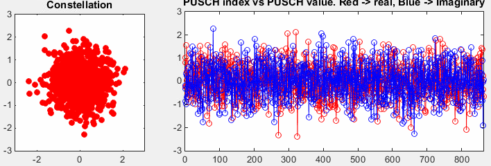
The output of ltePUSCH with 6 RB and QPSK: 864 values that form a cloud rather than four QPSK points.
The constellation is a cloud because ltePUSCH includes the transform precoding of 36.211 v19.3.0 clause 5.3.3. Each group of 72 QPSK symbols goes through a DFT of size 72, and every output value is a weighted sum of all 72 inputs. The sum of many random QPSK values has a distribution close to Gaussian, which is what the plot shows. The QPSK points appear again only after an inverse DFT, as the Displaying PUSCH Constellation section shows.
The DFT size must be 12 times a number of RBs of the form 2a 3b 5c, so that the transform stays efficient. 6 RB meets that rule. The parameter table beside the plot lists ue1.NSubframe = 0, while the code sets ue1.NSubframe = 1. The subframe number changes the scrambling sequence, so the individual values differ between the two, but the shape of the cloud does not.
864 PUSCH values with 6 RB : 12 SC-FDMA symbols of 72 subcarriers.ltePUSCH includes transform precoding : the output is DFT-spread, not plain QPSK.DFT size of 12 x 2a 3b 5c : 36.211 clause 5.3.3.
Displaying PUSCH OFDM Symbol Data
The PUSCH values of the previous section form one long vector. This section places them on the uplink resource grid, and then reads them back one SC-FDMA symbol at a time, so each of the 12 data symbols gets its own row.
ue1.NCellID = 0;
ue1.CyclicPrefixUL = 'Normal';
ue1.NSubframe = 1;
ue1.Hopping = 'Off';
ue1.NULRB = 6;
ue1.Shortened = 0;
ue1.NTxAnts = 1;
ue1.SeqGroup = 0;
ue1.CyclicShift = 0;
ue1.RNTI = 1;
pusch.PRBSet = (0:5).';
pusch.Modulation = 'QPSK';
pusch.RV = 0;
pusch.DynCyclicShift = 0;
pusch.NLayers = 1;
pusch.OrthCover = 'Off';
pusch_dmrs_sym = ltePUSCHDRS(ue1,pusch);
pusch_dmrs_sym_arrayIndex = 0:length(pusch_dmrs_sym)-1;
pusch_dmrs_sym_ind = ltePUSCHDRSIndices(ue1,pusch);
pusch_trblk = round(rand(1,504));
pusch_cw = lteULSCH(ue1,pusch,pusch_trblk);
pusch_sym = ltePUSCH(ue1,pusch,pusch_cw);
pusch_sym_arrayIndex = 0:length(pusch_sym)-1;
pusch_sym_ind = ltePUSCHIndices(ue1,pusch);
resourceGridUL = lteULResourceGrid(ue1);
resourceGridUL(pusch_dmrs_sym_ind) = pusch_dmrs_sym;
resourceGridUL(pusch_sym_ind) = pusch_sym;
phy_sym_length = ue1.NULRB * 12;
pusch_sym_ind_matrix = reshape(pusch_sym_ind,phy_sym_length,12);
phy_sym_ind = pusch_sym_ind(1:phy_sym_length);
plot_sym_range = 1:length(phy_sym_ind);
for pusch_sym_no = 1:12
phy_sym_data = resourceGridUL(pusch_sym_ind_matrix(:,pusch_sym_no));
subplot(12,6,6*(pusch_sym_no-1) + 1);
plot(real(phy_sym_data),imag(phy_sym_data),'ro','MarkerFaceColor',[1 0 0]);
axis([-3 3 -3 3]);
set(gca,'xticklabel',[]); set(gca,'yticklabel',[]);
set(gca,'xtick',[]);set(gca,'ytick',[]);
subplot(12,6,[(6*(pusch_sym_no-1) + 2) : (6*(pusch_sym_no-1) + 6)]);
plot(plot_sym_range,real(phy_sym_data),'ro-',...
plot_sym_range,imag(phy_sym_data),'bo-');
xlim([0 max(plot_sym_range)]);
set(gca,'xticklabel',[]); set(gca,'yticklabel',[]);
set(gca,'xtick',[]);set(gca,'ytick',[]);
end;
The code writes the DMRS and the PUSCH into the grid from lteULResourceGrid. It then reshapes the 864 PUSCH indices into a 72 by 12 matrix, one column per SC-FDMA symbol that carries data. The loop plots each column in its own row: the constellation on the left, and the real and imaginary parts across the 72 subcarriers on the right. The DMRS symbols 3 and 10 are not part of the loop.
|
ue1.NCellID = 0; ue1.NSubframe = 0; ue1.NULRB = 6; ue1.Shortened = 0; ue1.NTxAnts = 1;
pusch.PRBSet = (0:5).'; pusch.Modulation = 'QPSK'; pusch.RV = 0; pusch.DynCyclicShift = 0; |
|
|
|
|
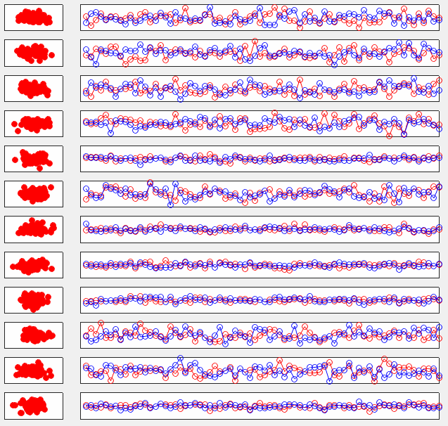
The 12 PUSCH SC-FDMA symbols as they sit on the subcarriers. Each row shows the same kind of cloud as the plot above.
These are the values that the subcarriers carry, so each row still shows the output of the DFT. Some rows vary more than others, because each row is the DFT of a different set of 72 QPSK symbols. The resource grid of the uplink therefore does not show the modulation directly, which is the main visible difference from a downlink OFDM grid.
One row per SC-FDMA symbol : 12 data symbols, DMRS symbols excluded.Subcarrier values are DFT outputs : no QPSK points on the grid itself.
Displaying PUSCH Constellation
If the grid does not show QPSK, where are the QPSK symbols? This section applies an inverse DFT to each SC-FDMA symbol of the grid, which reverses the transform precoding and brings the modulation symbols back.
ue1.NCellID = 0;
ue1.CyclicPrefixUL = 'Normal';
ue1.NSubframe = 1;
ue1.Hopping = 'Off';
ue1.NULRB = 6;
ue1.Shortened = 0;
ue1.NTxAnts = 1;
ue1.SeqGroup = 0;
ue1.CyclicShift = 0;
ue1.RNTI = 1;
pusch.PRBSet = (0:5).';
pusch.Modulation = 'QPSK';
pusch.RV = 0;
pusch.DynCyclicShift = 0;
pusch.NLayers = 1;
pusch.OrthCover = 'Off';
pusch_dmrs_sym = ltePUSCHDRS(ue1,pusch);
pusch_dmrs_sym_arrayIndex = 0:length(pusch_dmrs_sym)-1;
pusch_dmrs_sym_ind = ltePUSCHDRSIndices(ue1,pusch);
pusch_trblk = round(rand(1,504));
pusch_cw = lteULSCH(ue1,pusch,pusch_trblk);
pusch_sym = ltePUSCH(ue1,pusch,pusch_cw);
pusch_sym_arrayIndex = 0:length(pusch_sym)-1;
pusch_sym_ind = ltePUSCHIndices(ue1,pusch);
resourceGridUL = lteULResourceGrid(ue1);
resourceGridUL(pusch_dmrs_sym_ind) = pusch_dmrs_sym;
resourceGridUL(pusch_sym_ind) = pusch_sym;
phy_sym_length = ue1.NULRB * 12;
pusch_sym_ind_matrix = reshape(pusch_sym_ind,phy_sym_length,12);
phy_sym_ind = pusch_sym_ind(1:phy_sym_length);
plot_sym_range = 1:length(phy_sym_ind);
for pusch_sym_no = 1:12
phy_sym_freq_data = ifft(resourceGridUL(pusch_sym_ind_matrix(:,pusch_sym_no)));
subplot(12,6,6*(pusch_sym_no-1) + 1);
plot(real(phy_sym_freq_data),imag(phy_sym_freq_data),'ro','MarkerFaceColor',[1 0 0]);
axis([-0.2 0.2 -0.2 0.2]);
set(gca,'xticklabel',[]); set(gca,'yticklabel',[]);
set(gca,'xtick',[]);set(gca,'ytick',[]);
subplot(12,6,[(6*(pusch_sym_no-1) + 2) : (6*(pusch_sym_no-1) + 6)]);
plot(plot_sym_range,real(phy_sym_freq_data),'ro-',...
plot_sym_range,imag(phy_sym_freq_data),'bo-');
xlim([0 max(plot_sym_range)]);
set(gca,'xticklabel',[]); set(gca,'yticklabel',[]);
set(gca,'xtick',[]);set(gca,'ytick',[]);
end;
The only change from the previous code is the call ifft(...) on each column of the grid. 36.211 scales the transform precoding by 1/√M, and the Matlab ifft scales by 1/M. The two together leave the QPSK symbols scaled by 1/√72, so the points sit near 0.707 / 8.49 = 0.083. That is why the axis runs from -0.2 to 0.2 here, and not from -3 to 3.
|
ue1.NCellID = 0; ue1.NSubframe = 0; ue1.NULRB = 6; ue1.Shortened = 0; ue1.NTxAnts = 1;
pusch.PRBSet = (0:5).'; pusch.Modulation = 'QPSK'; pusch.RV = 0; pusch.DynCyclicShift = 0; |
|
|
|
|
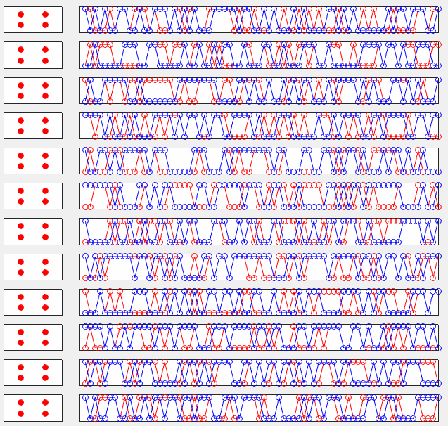
The same 12 symbols after an inverse DFT. Every row shows the four QPSK points, and the values jump between two levels.
The variable phy_sym_freq_data holds the result of the inverse DFT. Despite its name, it contains the modulation symbols before transform precoding, which is the domain the receiver works in after its own inverse DFT. A receiver does the same thing: it equalizes each subcarrier with the DMRS, applies an inverse DFT, and only then demodulates.
ifft reverses the transform precoding : the QPSK points reappear.Points near +/- 0.083 : QPSK scaled by 1/√72.phy_sym_freq_data holds symbols before the DFT : not frequency domain data.
Symbol to RE Mapping
Where on the grid does the PUSCH sit? This section marks the PUSCH and DMRS REs with fixed values, so the grid shows the allocation rather than the data. It allocates 5 RB, PRBSet = 0:4, on carriers of 6 and 25 RB.
ue1.NCellID = 0;
ue1.CyclicPrefixUL = 'Normal';
ue1.NSubframe = 0;
ue1.Hopping = 'Off';
ue1.NULRB = 6;
ue1.Shortened = 0;
ue1.NTxAnts = 1;
ue1.SeqGroup = 0;
ue1.CyclicShift = 0;
ue1.RNTI = 1;
pusch.PRBSet = (0:4).';
pusch.Modulation = 'QPSK';
pusch.RV = 0;
pusch.DynCyclicShift = 0;
pusch.NLayers = 1;
pusch.OrthCover = 'Off';
pusch_dmrs_sym = ltePUSCHDRS(ue1,pusch);
pusch_dmrs_sym_arrayIndex = 0:length(pusch_dmrs_sym)-1;
pusch_dmrs_sym_ind = ltePUSCHDRSIndices(ue1,pusch);
pusch_trblk = round(rand(1,504));
pusch_cw = lteULSCH(ue1,pusch,pusch_trblk);
pusch_sym = ltePUSCH(ue1,pusch,pusch_cw);
pusch_sym_arrayIndex = 0:length(pusch_sym)-1;
pusch_sym_ind = ltePUSCHIndices(ue1,pusch);
resourceGridUL = lteULResourceGrid(ue1);
pusch_scale = 0.5;
pusch_dmrs_scale = 1.0;
resourceGridUL(pusch_dmrs_sym_ind) = pusch_dmrs_scale; % * pusch_dmrs_sym;
resourceGridUL(pusch_sym_ind) = pusch_scale; % * pusch_sym;
resourceGridUL = [ resourceGridUL resourceGridUL(:,13)];
resourceGridUL = [ resourceGridUL; resourceGridUL((ue1.NULRB*12-1),:) ];
xStep = 0:14;
yStep = 0:(ue1.NULRB*12);
surface(xStep,yStep,abs(resourceGridUL));
axis([0 14 0 (ue1.NULRB*12) 0 2]);
view([0,90]);
set(gca,'xtick',[0 6 7 13]);
set(gca,'ytick',[[0:12:ue1.NULRB*12-1] [ue1.NULRB*12-1]]);
The code sets every PUSCH RE to 0.5 and every DMRS RE to 1.0. It then adds one extra row and column to the grid, because the function surface draws cells between grid points and would otherwise drop the last row and column.
|
ue1.NCellID = 0; ue1.NSubframe = 0; ue1.NULRB = 6; ue1.Shortened = 0; ue1.NTxAnts = 1;
pusch.PRBSet = (0:4).'; pusch.Modulation = 'QPSK'; pusch.RV = 0; pusch.DynCyclicShift = 0; |
ue1.NCellID = 0; ue1.NSubframe = 0; ue1.NULRB = 25; ue1.Shortened = 0; ue1.NTxAnts = 1;
pusch.PRBSet = (0:4).'; pusch.Modulation = 'QPSK'; pusch.RV = 0; pusch.DynCyclicShift = 0; |
|
|
|
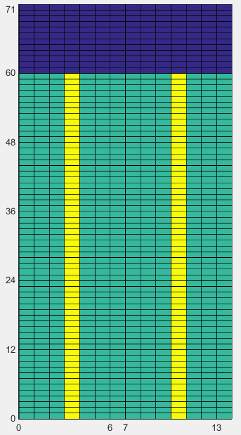
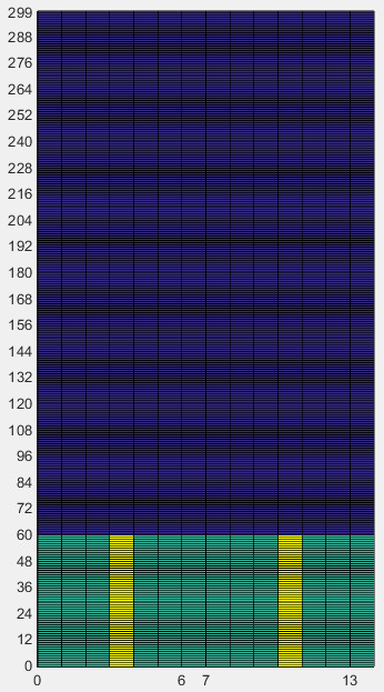
PUSCH on RB 0 to 4, subcarriers 0 to 59, with 6 RB on the left and 25 RB on the right. The DMRS in yellow take symbols 3 and 10.
The PUSCH fills subcarriers 0 to 59 in every symbol except 3 and 10, where the DMRS sit, as 36.211 clause 5.5.2.1.2 places them for the normal cyclic prefix. The PUSCH DMRS page covers those reference signals. The carrier size changes nothing in the allocation. On the 25 RB carrier, subcarriers 60 to 299 stay empty, and the dark horizontal bands there are cell edges drawn by surface, not signal.
Shortened PUSCH
A UE that sends an SRS in the same subframe must keep the last SC-FDMA symbol free for it. The same code with ue1.Shortened = 1 shows how the PUSCH gives up that symbol.
|
ue1.NCellID = 0; ue1.NSubframe = 0; ue1.NULRB = 6; ue1.Shortened = 1; ue1.NTxAnts = 1;
pusch.PRBSet = (0:4).'; pusch.Modulation = 'QPSK'; pusch.RV = 0; pusch.DynCyclicShift = 0; |
ue1.NCellID = 0; ue1.NSubframe = 0; ue1.NULRB = 25; ue1.Shortened = 1; ue1.NTxAnts = 1;
pusch.PRBSet = (0:4).'; pusch.Modulation = 'QPSK'; pusch.RV = 0; pusch.DynCyclicShift = 0; |
|
|
|
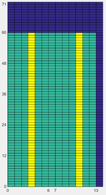
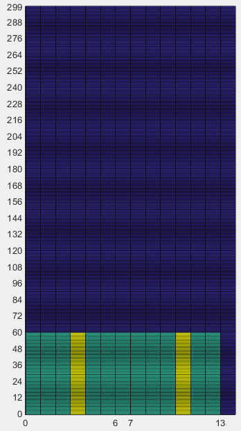
Shortened PUSCH on RB 0 to 4. Symbol 13 is now empty on both carriers.
36.211 clause 5.3.4 excludes the last SC-FDMA symbol from the PUSCH when the UE transmits SRS in the same subframe. The PUSCH then carries 11 data symbols instead of 12, which is 660 REs instead of 720 with 5 RB, and rate matching fits the codeword to the smaller size. The DMRS positions do not change. The UL SRS page shows the signal that uses that last symbol.
PUSCH on the allocated RBs : every symbol except the DMRS symbols 3 and 10.5 RB allocation : subcarriers 0 to 59 on either carrier.Shortened = 1 : symbol 13 left free for SRS.
Disclaimer !
This page is only to show you the overall logics and visualization for various LTE physical layer channels. I haven't investigated much about verifying about the accuracy.
If you think the code is not so efficient, it is 100% my fault. I haven't made any effort for effiecient code. I just tried to create code as simple as possible for the readers. As you know, easy-to-read code is not always efficient for a specific chipset.
If you find any mistake in terms of accuracy, it is also very highly likely be my fault. Not the problem of Matlab tool box itself.
Any comment and corrections if you find any mistake will be welcome and appreciated.
Reference
[1] 3GPP TS 36.211 v19.3.0 - clauses 5.3.3 and 5.3.4, Transform precoding and PUSCH mapping; clause 5.5.2.1.2, DMRS mapping