|
Data Throughput |
||
|
Data Throughput Overview
I have been being asked to troubleshot the throughput issue so many times. Unfortunately my experience says "There is no clear/logical/deterministic way to troubleshoot for throughput test". Then what are we supposed to do ? Are we supposed to rely on "Hit and Miss" strategy everytime we do the throughput test ? Is this process totally random ? No at least we are not in such a worst case, fortunately. I think we can set some guidelines at least.
Almost every time when a new technology comes, what we we hear most frequently would be 'you can download a movie in less than a minuite (in early LTE case)' or 'you can download a movie in a few seconds (in early 5G case)'. Usually the most common reaction to this kind of (marketing ?) statement would be
I don't think I need to answer to the first question. Everybody says 'who would need such a high speed ?', but nobody complains when it really comes and start complaining about the low throughput a few years later. However high speed you get, a lot of new applications or use cases comes that let such a big pipe look limiting. In my personal experience, I think I've heard the same question (i.e, 'who would need such a high speed) since early HSDAP which is just a few Mbps) and I am still hearing complaints about the low throughput at the period of tens of Mbps. So.. my answer to this question is 'don't worry, you will soon want to get the big pipe'.
What I am trying to do in this section is more about answering the second question : Why I don't see the same throughput on my phone ? In short, it is very unlikely that you would see the same throughput on your phone if you are trying it in live network as a regular subscriber. Why not ? There are two common reason as below
For example, if you are talking about around 6 Gbps speed for 5G(NR), it would belong to the first case. If you are talking about 20 Gbps, it would belong to the second case at the time of writing this (Nov 2020). I am not going to talk more about the second case. I will be focusing more on the first case.... i.e, what would be the special condition that let such a tremendous speed come true ?
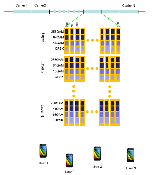
There are several factors that is critical to determine the throughput can be summarized in an illustration as shown below. This logic applies at least to 4G and 5G. 3G throughput (i.e, HSPA) is determined by a little bit different set of factors(parameters) but I would focus more on 4G/5G throughput. If you are interested in 3G throughput, refer to this note. Let me comment a little bit about this illustration this illustration. The comments written below is just written description of the illustration.. meaning the description and the illustration represents a same thing.
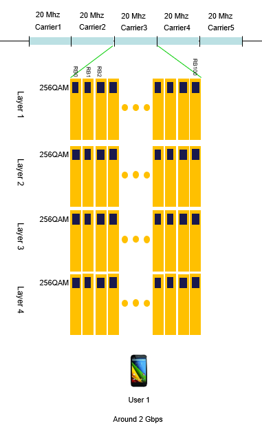
Typical condition for LTE max throughput
At the point of writing this part (Nov 2020), I think the typical condition for achieving the max throughput in LTE can be illustrated as follows.
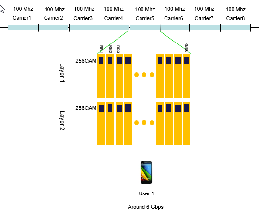
Typical Condition for 5G/NR max throughput
At the point of writing this part (Nov 2020), I think the typical condition for achieving the max throughput in 5G/NR can be illustrated as follows.
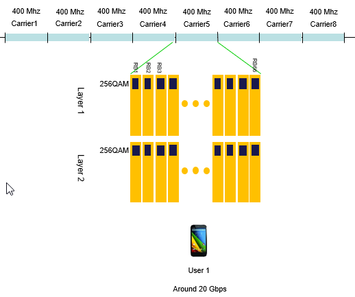
As far as I know as of now (Nov 2020), I don't see anything that supports the speed shown below, but this would be realizable at least in terms of 3GPP specification.
NOTE : In NR TDD case, there are ofther factors affecting the achievable throughput. They are the scheduling ratio of Downlink and Uplink, and the number of symbols assigned for each slots. It is assumed that slot and symbols are scheduled for downlink as much as possible.
First thing to remember for throughput troubleshooting
One sentence. "Throughput troubleshooting is not simple at all.", "Don't expect it to be simple.". If I solved the problem with single shot, I would say "I was just lucky, It is not because I am technically competent".
Even troubleshooting with wired communication is not easy. Think about how many more factors would get involved in the data path.
That's all for the first thing. Now let's move to the second important thing for this issue. What is the second thing ?
It's "Don't give up. You will eventually find the solution!" -:). It is just matter of time and depend on how much dedicated you are during the troubleshoot.
Now the third things comes (Many people think this is the first thing since it sound more technical, but I don't think it is the case). What I want you to do as the third item is "list up all the nodes from the data transmitter to the reciever, and follow all the steps without skipping anything.". One example I can give you is (this is an example where you use a Network Emulator for the test). i) IP Application Software on PC (e.g, iperf, FileZilla) ii) TE port on PC (e.g, Ethernet Card). iii) TE port on throughput test equipment (e.g, Data packet port on Network Emulator) iv) PDCP layer on test equipment v) RLC layer on test equipment vi) MAC layer on test equipment vii) L1 (Transport and PHY) layer on test equipment viii) L1 (Transport and PHY) layer on UE (mobile phone or data card) ix) MAC layer on UE x) RLC Layer on UE xi) PDCP layer on UE xii) TE port on UE (e.g, Modem connector) xiii) TE port on PC (e.g, USB port the UE is connected to) xiv) IP Application Software on PC to which the UE is connected.
The more you understand on each of these items, the better position you are in for troubleshooting. (If you really enjoy your job as engineer, one of the topic I would recommend you is to try with throughput troubleshoot or optimization. To me it looks like an art at the same time being a technology).
Now you would ask "Which component on the list is most important, most critical factor for the throughput ?". I wish I had a simple/clear answer to this, but my experience says "the answer varies depending on the situation". Especially it would differ depending on what kind of radio technoloty your device is using. (e.g, Is it R99 WCDMA Device, HSDPA, HSPA+, LTE ?)
In addition to the major technical factors listed above, sometimes very simple things as follows make you spend several hours to several weeks for troubleshoot if you are in bad luck. i) LAN Cable type (Sometimes you have to use 'direct cable' and sometimes you have to use 'cross over' cable). ii) Category of LAN cable. (Is it Cat 5 cable or Cat 6 cable ?) iii) Ethernet Port Capability (Is it only for 10/100 M, or Gigabit ethernet ?) iv) Firewall setting on your PC (I will go back to this later in a separate section).
I will try to go through each type of radio technology and try to point out the important factor for that specific technology. (Try to memorize all the steps listed above sicne I will talk about the steps for each of the following sections).
I often see two extreme opinion on the result of throughput test result. Followings are those two with example LTE Cat3 MIMO download throughput.
Opinion 1 : I know the ideal max throughput is 100 Mbps, but I think it doesn't make much sense at least for a mobile device because in live network, you would never be in such a situation where a network allow such a huge resource allocation for any single UE and Radio Signal Quality also would not be good enough to achieve those throughput. so I am happy if the throughput result gives 30~40 Mbps. <== I wrote this comments around 6 years (2011) ago when LTE is at relatively early stage of deployment. But now (Jun 2018), the device supporting 1Gbps is not uncommon and we are talking about 1.6 Gbps and even 2.0 Gbps device. Nobody think 100 Mbps is too high throughput. My point is that all the technology evolve like this. When a technology comes out, many people think it is 'too much' but just in a few years it becomes 'too little'.
Opinion 2 : The 3GPP sepecfication says the Max throughput for LTE Cat 3 is 100 Mbps, so I want to get exact 100 Mbps throughput displayed on my IP traffic monitoring tool.
I think there is problem with both opinion, but I would not say much on Opinion 1. Just think you are lucky if your customer has this kind of opinion -:).
I will talk something about Opinion 2 in this section. What would be the problem of this opinion ? First he should not expect to get the same number on IP traffic monitor as 3GPP spec sheet shows, because what 3GPP spec sheets shows is the physical layer throughput, not the IP layer throughput. Between physical layer and IP layer, there are various kinds of overhead getting inserted. So it is natural to see a little bit less throughput on IP traffic monitor than the number on 3GPP spec sheets. Then you may ask.. what if we want to measure only PHY throughput. Will I get the same Max throughput as the 3GPP spec document says ? In WCDMA, HSDPA, HSUPA probably 'Yes', but in LTE you would still have a little low throughput than the 3GPP spec value even in PHY throughput. It is because there is some subframes where you cannot allocate full RBs (100 RBs in case of 20Mhz, Cat 3). These frames are where SIBs are scheduled. Especailly SIB2 is causing a lot of overhead because it is supposed to be transmitted at subframe 5 at every two SFN. The amount of phyiscal layer overhead varies depending on how eNodeB allocate RBs for user data for the subframe where the SIB is transmitted. According to my experience, I saw roughly three different strategies for this case.
Option 1 : eNodeB still allocate RBs for the SIB transmission subframe, but the number of RB is a little bit lower than the Max RB Option 2 : eNodeB does not allocate any RBs for user data at SIB transmission subframe. Option 3 : eNodeB stop transmitting SIBs when connected state and allocate the MAX RBs even for the SIB transmission subframe.
I think live network eNodeB is using Option 1 and I saw most of test equipment is using Option 2 or Option 3. But Option 3 may cause some unexpected side effect and this options is not widely used. So in theory, you may get a little bit higher throughput if you use real eNodeB in 'test lab' (not in live network) comparing to test equipment. (You would get much less throughput in live network because you cannot control the eNodeB as you want and the signal quality is not as good as in the test lab. ).
In concolusion, whatever method you use you would not get the 100% same as specified in 3GPP specification. In my personal opinion, it would be considered OK if you can achieve around 90% of the ideal Max throughput without much of packet error. (If the difference between the test throughput and ideal throughput is due to packet area, not much due to overhead.. you'd better investigate further to find the root cause of the problem).
Milestones in the history of throughput evolution
I've been involved in throughput testing for Cellular devices since UMTS HSPA and I had seen some stumbling blocks for almost each and every steps of evolution. These stumbling block is not only from the DUT (Cellular device) but also from other components which constitues the test system. In this section, I would list up some of the milestones (stepping stones) that I've gone through. Some of the items list I will add some troubleshoot tips for each of the milestones, but it may not be a direct solution to the problem that you are facing since there are so many factors get involved in the data path and root cause of a problem may be different for different problem even though the symptom looks similar. However, the factors that I am listing here might be at least something worth considering for your own troubleshooting process.
This was around 6 or 7 years ago (around 2010/2011). Nobody would think this is any big problem these days and they would classfy this as a very low throughput case. However, when LTE first came out this was pushing the limit not only on DUT(Cellular protocol) but also many other parts a well. Followings are some of the factors that would cause issues.
< LTE Category 18,19,20 : 1.2.1.6,2.0 Gbps >
|
||