I would say PDCP is a kind of interface between inside world and outside world. By "Inside World", I roughly mean "Network Access Network(mainly eNodeB) and Controller for eNodeB", "Network Emulator Hardware and internal firmware", and "Mobile Device (UE)". PDCP is a layer sitting at the top most part of the radio stack. In terms of basic operation, what PDCP does seems very simple. Just "adding the PDCP header to the incoming data and forward to RLC in downlink", or "removing the PDCP header from the incoming packet and forward it to IP layer in case of uplink" is all that it does. However, this layer can be pretty busy stack if you enables various additional features like Integrity, Ciphering and Header Compression. Recently (from Rel 12) as Dual Connectivity (Split Bearer) is supported, this layer has become much busier.
This page follows PDCP from the outside in. It starts with the functions and the two 36.323 diagrams. It then shows the NAS and RRC messages that configure PDCP, the maximum packet size, the PDU formats and the integrity protection inputs. It ends with four PDCP PDUs decoded byte by byte.
- Overview / Overall Functionality
- RRC Parameters for PDCP Configuration
- Maximu PDCP Packet Size
- PDCP Data Structure
- Integrity Protection Process
- Examples of PDCP Data Structure
- Reference
Overview / Overall Functionality
The data coming into the box (eNB or UE) first go through PDCP and then gets into RLC (Downlink Path). Data waiting in RLC trying to go out to the outside world has to go through PDCP to reach outside world(Uplink Path).
In the case when everything goes OK, you don't see any problems in protocol stack and just check protocol log you may think the function of PDCP looks simple and all it does is just to add/remove a small header to each packet and send/recieve it from/to RLC. But if you list up all the detailed functions of PDCP, you would get pretty long list as shown below.
- Transfer of Data (C-Plane and U-Plane) between RLC and Higher U-Plane interface
- Maintenance of PDCP SN(Sequence Number)
- Transfer of SN Status (for use Upon Handover)
- ROHC (Robust Header Compression)
- In-Sequence delivery of Upper Layer PDUs at re-establishment of lower layer
- Elimination of duplicate of lower layer SDUs at re-establishment of lower layer for RLC AM
- Ciphering and Deciphering of C-Plane and U-Plane data
- Integrity Protection and Integrity verification of C-Plane Data
- Timer based Discard
- Duplicate Discard
- For split and LWA bearers, routing and reordering.
The list above is the Release 13 view. 36.323 v19.0.0 clause 4.4 keeps every one of these functions and adds more. Release 15 added uplink data compression, UDC, and duplicate transmission for PDCP duplication. Release 16 added Ethernet header compression, EHC, and routing and reordering for DAPS bearers, which serve DAPS handover. Integrity protection also reaches beyond SRBs. A relay node can protect its DRBs, and sidelink one-to-one communication protects its SLRBs.
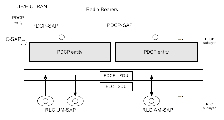
As in other layers, let's start looking into the diagram from 3GPP specification (TS 36.323). The first diagram is as follows.
What are we supposed to do ?
Yes, Verbalize it (describe it). i.e, explain the diagram in your own words.
In the following diagram, you see that PDCP is directly connected to RLC Layer (RLC UM and RLC AM).
Do you find anything strange or missing ?
Yes, PDCP has no connection to RLC TM mode, meaning RLC TM mode data does not go through PDCP.
The reason is the logical channel. 36.323 clause 4.4 says that PDCP serves only DCCH, DTCH and STCH. SRB0 uses CCCH on RLC TM, so RRC Connection Request and RRC Connection Setup reach RLC without any PDCP header. SRB1bis, which NB-IoT uses, does not go through PDCP either.
< 36.323 - Figure 4.2.1.1 - PDCP layer, structure view >
Following Diagram would give you more detailed information about PDCP Operation. Of course, all of the these functionality is listed in the 3GPP specification, but it would not become yours unless you combine these diagrams and the written descriptions in your own words.
Now let's follow through the diagram from left side.
- i) Data coming into PDCP first go through "Sequence Numbering" Procedure. It means that PDCP add "Sequence Number" to each of incoming data block. Once it add 'Sequence Number', it has to manage the number. On reciever side, we can figure out many things like "Is the data getting delivered in order ? Is there any duplicate data ? How can I combine the multiple chunks of data block into an original big chunk data ?"
- ii) Then it goes through Header Compression. But it says "this applies only to U-plane data". It means that Signaling Message does not go through this Header Compression. Even though not shown in this diagram, we can disable Header Compression even for U-plane data (e.g, IP Packet data).
- iii) From here we see two paths, one through "Integrity/Ciphering" and the other one directly goes to the last step. Integrity Protection applies only to C-Plane data (C-Plane data means RRC/NAS message, i.e DCCH data, not DTCH data). Again you can disable "Integrity Protection" setp by applying EIA0 to this process.
- iv) Then it goes to Ciphering process. Ciphering applies both C-Plane and U-Plane Data. Ciphering process can also be disabled by applying EEA0.
- v) Eventually at the last step of transmission PDCP, a header is added and get out of PDCP layer.
The other side (right side, receiving side) is simply reverse process of transmission process. So I will leave this to the readers to interpret the diagram.
< 36.323 - Figure 4.2.2.1 - PDCP layer, functional view >
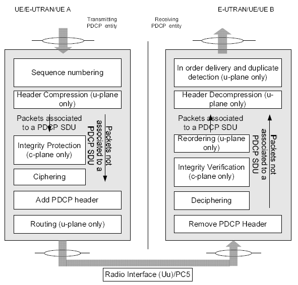
Notice two boxes that the step list above does not cover. On the transmitting side, Routing (u-plane only) sits under Add PDCP header. On the receiving side, Reordering (u-plane only) sits above Integrity Verification. Both arrived with dual connectivity in Release 12 and LWA in Release 13. A split bearer has one PDCP entity and two RLC entities, so the transmitter chooses a path for each PDU. The receiver then gets PDUs from two paths out of order. It reorders them under the t-Reordering timer before in-order delivery.
PDCP serves DCCH, DTCH and STCH only : CCCH traffic on RLC TM, such as SRB0, carries no PDCP header.Integrity protection is for the C-plane : ciphering covers both planes, and the MAC-I exists only on SRBs, apart from relay node DRBs.Split bearers add routing and reordering : one PDCP entity feeds two RLC entities from Release 12.The function list keeps growing : UDC and duplication in Release 15, EHC and DAPS in Release 16.
RRC Parameters for PDCP Configuration
As you might have noticed at the descriptions in previous section, the PDCP operation can be very simple or pretty complex depending configuration. Then you may ask 'how we can configure PDCP operation ?'. These are configured by Higher Layer Signaling message (i.e, RRC or NAS message).
Ciphering and Integrity functionality of PDCP is configured by Security Mode Command message and other PDCP functionality is configured by RRC Connection Reconfiguration or RRC Connection Setup message as shown in the following examples.
From very basic PDCP configuration based on Release 8 and pretty complicated configurations based on Release 13, you would notice how PDCP has evolved from old specification to more recent specification. Of course, you don't need to enable all of those features shown in Release 13 example, but it would be obvious that the set of possible options has been expanded greatly as it evolves to recent standard.
EMM : Security Mode Command
The NAS Security Mode Command comes first. The MME uses it to select the algorithms for NAS messages, and this capture selects EEA0 and 128-EIA2. These algorithms protect NAS messages only. PDCP gets its own algorithms from the RRC message in the next block.
Decoded message from a tester log,
Security mode command ::= DIVISION
  +-Security header type ::= V
  | +-Security header type ::= CHOICE [Plain NAS message, not security protected]
  +-EPS mobility management protocol discriminator ::= V
  +-Security mode command message identity ::= V
  +-Selected NAS security algorithms ::= V
  | +-Octet1 ::= DIVISION
  |   +-spare ::= FIX [0]
  |   +-Type of ciphering algorithm ::= EPS encryption algorithm EEA0 (null ciphering algorithm)
  |   +-spare ::= FIX [0]
  |   +-Type of integrity protection algorithm ::= EPS integrity algorithm 128-EIA2
  +-Spare half octet ::= V
  +-NAS key set identifier ::= V
  | +-TSC ::= CHOICE [native security context (for KSI ASME)]
  | +-NAS key set identifier ::= CHOICE [possible values for the NAS key set identifier 0]
  +-Replayed UE security capabilities ::= LV
  +-IMEISV request ::= TV OPTIONAL:Omit
  +-Replayed nonce UE ::= TV OPTIONAL:Omit
  +-Nonce MME ::= TV OPTIONAL:Omit
The capture shows Security header type as a plain NAS message. On the air, 24.301 v20.0.0 clause 5.4.3.2 has the MME send this message integrity protected with the new EPS security context, but unciphered. The capture therefore shows the plain NAS message inside that protected wrapper.
RRC : Security Mode Command
The RRC Security Mode Command does the same job for the AS. The eNB uses it to set the algorithms that PDCP applies to SRBs and DRBs. This capture selects eea0 and eia2, so the UE gets integrity protection without ciphering.
Decoded message from a tester log,
+-securityModeCommand-r8 ::= SEQUENCE [0]
  +-securityConfigSMC ::= SEQUENCE
  | +-securityAlgorithmConfig ::= SEQUENCE
  | | +-cipheringAlgorithm ::= ENUMERATED [eea0]
  | | +-integrityProtAlgorithm ::= ENUMERATED [eia2]
  | +-EXTENSION ::= SEQUENCE
  +-nonCriticalExtension ::= SEQUENCE OPTIONAL:Omit
Following is based on
SecurityAlgorithmConfig ::=         SEQUENCE {
    cipheringAlgorithm                  CipheringAlgorithm-r12,
    integrityProtAlgorithm              ENUMERATED {
                                            eia0-v920, eia1, eia2, eia3-v1130, spare4, spare3,
                                            spare2, spare1, ...}
}

CipheringAlgorithm-r12 ::=              ENUMERATED {
                                            eea0, eea1, eea2, eea3-v1130, spare4, spare3,
                                            spare2, spare1, ...}
In the current release, cipheringAlgorithm has the type CipheringAlgorithm-r12, and the list of values has not changed. The suffix on a value shows when it was added. The value eia0-v920 came in Release 9, and the ZUC based eea3-v1130 and eia3-v1130 came in Release 11. Keep one limit in mind here. 33.401 v19.2.0 clause 5.1.4 allows EIA0 only for unauthenticated emergency calls, so eia0 is not a normal way to switch integrity protection off.
Both captures select null ciphering with integrity protection. That is why the RRC message in the first example on this page can be read directly after the PDCP header, while its MAC-I still carries a real value.
RRC Connection Reconfiguration / RRC Connection Setup - Basic Configuration / Release 8
The Release 8 configuration is the minimum a DRB needs. The discardTimer is infinity, and the RLC AM bearer sends a PDCP status report after re-establishment. Header compression is not used. The pdcp-Config IE sits inside DRB-ToAddMod, next to rlc-Config, because PDCP is configured per DRB. SRB-ToAddMod has no PDCP configuration at all.
Decoded message from a tester log,
+-rrcConnectionReconfiguration-r8 ::= SEQUENCE [001100]
  +-measConfig ::= SEQUENCE OPTIONAL:Omit
  +-mobilityControlInfo ::= SEQUENCE OPTIONAL:Omit
  +-dedicatedInfoNASList ::= SEQUENCE OF SIZE(1..maxDRB[11]) [1] OPTIONAL:Exist
  +-radioResourceConfigDedicated ::= SEQUENCE [110101] OPTIONAL:Exist
  | +-srb-ToAddModList ::= SEQUENCE OF SIZE(1..2) [1] OPTIONAL:Exist
  | +-drb-ToAddModList ::= SEQUENCE OF SIZE(1..maxDRB[11]) [1] OPTIONAL:Exist
  | | +-DRB-ToAddMod ::= SEQUENCE [11111]
  | |   +-eps-BearerIdentity ::= INTEGER (0..15) [5] OPTIONAL:Exist
  | |   +-drb-Identity ::= INTEGER (1..32) [1]
  | |   +-pdcp-Config ::= SEQUENCE [110] OPTIONAL:Exist
  | |   | +-discardTimer ::= ENUMERATED [infinity] OPTIONAL:Exist
  | |   | +-rlc-AM ::= SEQUENCE OPTIONAL:Exist
  | |   | | +-statusReportRequired ::= BOOLEAN [TRUE]
  | |   | +-rlc-UM ::= SEQUENCE OPTIONAL:Omit
  | |   | +-headerCompression ::= CHOICE [notUsed]
  | |   | | +-notUsed ::= NULL
  | |   +-rlc-Config ::= CHOICE [am] OPTIONAL:Exist
  | |   +-logicalChannelIdentity ::= INTEGER (3..10) [3] OPTIONAL:Exist
  | |   +-logicalChannelConfig ::= SEQUENCE [1] OPTIONAL:Exist
  | +-drb-ToReleaseList ::= SEQUENCE OF OPTIONAL:Omit
  | +-mac-MainConfig ::= CHOICE [explicitValue] OPTIONAL:Exist
  | +-sps-Config ::= SEQUENCE OPTIONAL:Omit
  | +-physicalConfigDedicated ::= SEQUENCE [0000111010] OPTIONAL:Exist
  +-securityConfigHO ::= SEQUENCE OPTIONAL:Omit
  +-nonCriticalExtension ::= SEQUENCE OPTIONAL:Omit
RRC Connection Reconfiguration / RRC Connection Setup - Full Configuration / Release 13
The Release 13 capture shows how far the same IE had grown. Each field added from Release 10 to Release 13 sits in its own extension group, and the tester labels these groups VERSION-BRACKETS1 to VERSION-BRACKETS4.
Decoded message from a tester log,
+-rrcConnectionReconfiguration-r8 ::= SEQUENCE [001100]
  +-measConfig ::= SEQUENCE OPTIONAL:Omit
  +-mobilityControlInfo ::= SEQUENCE OPTIONAL:Omit
  +-dedicatedInfoNASList ::= SEQUENCE OF SIZE(1..maxDRB[11]) [1] OPTIONAL:Exist
  +-radioResourceConfigDedicated ::= SEQUENCE [110101] OPTIONAL:Exist
  | +-srb-ToAddModList ::= SEQUENCE OF SIZE(1..2) [1] OPTIONAL:Exist
  | +-drb-ToAddModList ::= SEQUENCE OF SIZE(1..maxDRB[11]) [1] OPTIONAL:Exist
  | | +-DRB-ToAddMod ::= SEQUENCE [11111]
  | |   +-eps-BearerIdentity ::= INTEGER (0..15) [5] OPTIONAL:Exist
  | |   +-drb-Identity ::= INTEGER (1..32) [1]
  | |   +-pdcp-Config ::= SEQUENCE [111] OPTIONAL:Exist
  | |   | +-discardTimer ::= ENUMERATED [infinity] OPTIONAL:Exist
  | |   | +-rlc-AM ::= SEQUENCE OPTIONAL:Exist
  | |   | | +-statusReportRequired ::= BOOLEAN [TRUE]
  | |   | +-rlc-UM ::= SEQUENCE OPTIONAL:Exist
  | |   | | +-pdcp-SN-Size ::= ENUMERATED [len7bits]
  | |   | +-headerCompression ::= CHOICE [rohc]
  | |   | | +-rohc ::= SEQUENCE [1]
  | |   | |   +-maxCID ::= INTEGER (1..16383) [1] OPTIONAL:Exist
  | |   | |   +-profiles ::= SEQUENCE
  | |   | |   | +-profile0x0001 ::= BOOLEAN [TRUE]
  | |   | |   | +-profile0x0002 ::= BOOLEAN [TRUE]
  | |   | |   | +-profile0x0003 ::= BOOLEAN [FALSE]
  | |   | |   | +-profile0x0004 ::= BOOLEAN [FALSE]
  | |   | |   | +-profile0x0006 ::= BOOLEAN [FALSE]
  | |   | |   | +-profile0x0101 ::= BOOLEAN [FALSE]
  | |   | |   | +-profile0x0102 ::= BOOLEAN [FALSE]
  | |   | |   | +-profile0x0103 ::= BOOLEAN [FALSE]
  | |   | |   | +-profile0x0104 ::= BOOLEAN [FALSE]
  | |   | |   +-EXTENSION ::= SEQUENCE
  | |   | +-EXTENSION ::= SEQUENCE [1111]
  | |   |   +-VERSION-BRACKETS1 ::= SEQUENCE [1] OPTIONAL:Exist
  | |   |   | +-rn-IntegrityProtection-r10 ::= ENUMERATED [enabled] OPTIONAL:Exist
  | |   |   +-VERSION-BRACKETS2 ::= SEQUENCE [1] OPTIONAL:Exist
  | |   |   | +-pdcp-SN-Size-v1130 ::= ENUMERATED [len15bits] OPTIONAL:Exist
  | |   |   +-VERSION-BRACKETS3 ::= SEQUENCE [11] OPTIONAL:Exist
  | |   |   | +-ul-DataSplitDRB-ViaSCG-r12 ::= BOOLEAN [TRUE] OPTIONAL:Exist
  | |   |   | +-t-Reordering-r12 ::= ENUMERATED [ms0] OPTIONAL:Exist
  | |   |   +-VERSION-BRACKETS4 ::= SEQUENCE [111] OPTIONAL:Exist
  | |   |     +-ul-DataSplitThreshold-r13 ::= CHOICE [setup] OPTIONAL:Exist
  | |   |     | +-setup ::= ENUMERATED [b0]
  | |   |     +-pdcp-SN-Size-v1310 ::= ENUMERATED [len18bits] OPTIONAL:Exist
  | |   |     +-statusFeedback-r13 ::= CHOICE [setup] OPTIONAL:Exist
  | |   |       +-setup ::= SEQUENCE [1111]
  | |   |         +-statusPDU-TypeForPolling-r13 ::= ENUMERATED [type1] OPTIONAL:Exist
  | |   |         +-statusPDU-Periodicity-Type1-r13 ::= ENUMERATED [ms5] OPTIONAL:Exist
  | |   |         +-statusPDU-Periodicity-Type2-r13 ::= ENUMERATED [ms5] OPTIONAL:Exist
  | |   |         +-statusPDU-Periodicity-Offset-r13 ::= ENUMERATED [ms1] OPTIONAL:Exist
  | |   +-rlc-Config ::= CHOICE [am] OPTIONAL:Exist
  | |   +-logicalChannelIdentity ::= INTEGER (3..10) [3] OPTIONAL:Exist
  | |   +-logicalChannelConfig ::= SEQUENCE [1] OPTIONAL:Exist
  | |   +-EXTENSION ::= SEQUENCE [00]
  | +-drb-ToReleaseList ::= SEQUENCE OF OPTIONAL:Omit
  | +-mac-MainConfig ::= CHOICE [explicitValue] OPTIONAL:Exist
  | +-sps-Config ::= SEQUENCE OPTIONAL:Omit
  | +-physicalConfigDedicated ::= SEQUENCE [0000111010] OPTIONAL:Exist
  +-securityConfigHO ::= SEQUENCE OPTIONAL:Omit
  +-nonCriticalExtension ::= SEQUENCE OPTIONAL:Omit
Read this capture as a list of fields, not as a working configuration. 36.331 would not allow several combinations in it. First, rlc-AM and rlc-UM are both present, but the conditions Rlc-AM-UM and Rlc-UM allow only the one that matches the RLC mode. Second, pdcp-SN-Size-v1310 is present together with pdcp-SN-Size-v1130, but condition Rlc-AM3 allows it only when pdcp-SN-Size-v1130 is absent. Third, rn-IntegrityProtection-r10 is signalled only to a relay node, and statusFeedback-r13 is configured only for an LWA DRB.
PDCP-Config in the Latest Release
The captures above stop at Release 13. The current definition shows what Release 14 to Release 17 added after the Release 13 extension group. The listing below is the whole IE, with the two types it refers to.
Following is based on
PDCP-Config ::=                     SEQUENCE {
    discardTimer                        ENUMERATED {
                                            ms50, ms100, ms150, ms300, ms500,
                                            ms750, ms1500, infinity
    }                                                           OPTIONAL,           -- Cond Setup
    rlc-AM                              SEQUENCE {
        statusReportRequired                BOOLEAN
    }                                                           OPTIONAL,           -- Cond Rlc-AM-UM
    rlc-UM                              SEQUENCE {
        pdcp-SN-Size                        ENUMERATED {len7bits, len12bits}
    }                                                           OPTIONAL,           -- Cond Rlc-UM
    headerCompression                   CHOICE {
        notUsed                             NULL,
        rohc                                SEQUENCE {
            maxCID                              INTEGER (1..16383)              DEFAULT 15,
            profiles                            SEQUENCE {
                profile0x0001                       BOOLEAN,
                profile0x0002                       BOOLEAN,
                profile0x0003                       BOOLEAN,
                profile0x0004                       BOOLEAN,
                profile0x0006                       BOOLEAN,
                profile0x0101                       BOOLEAN,
                profile0x0102                       BOOLEAN,
                profile0x0103                       BOOLEAN,
                profile0x0104                       BOOLEAN
            },
            ...
        }
    },
    ...,
    [[  rn-IntegrityProtection-r10      ENUMERATED {enabled}    OPTIONAL    -- Cond RN
    ]],
    [[  pdcp-SN-Size-v1130              ENUMERATED {len15bits}  OPTIONAL    -- Cond Rlc-AM2
    ]],
    [[  ul-DataSplitDRB-ViaSCG-r12      BOOLEAN     OPTIONAL,   -- Need ON
        t-Reordering-r12                ENUMERATED {
                                        ms0, ms20, ms40, ms60, ms80, ms100, ms120, ms140,
                                        ms160, ms180, ms200, ms220, ms240, ms260, ms280, ms300,
                                        ms500, ms750, spare14, spare13, spare12, spare11, spare10,
                                        spare9, spare8, spare7, spare6, spare5, spare4, spare3,
                                        spare2, spare1}                 OPTIONAL    -- Cond SetupS
    ]],
    [[  ul-DataSplitThreshold-r13       CHOICE {
            release                     NULL,
            setup                       ENUMERATED {
                                        b0, b100, b200, b400, b800, b1600, b3200, b6400, b12800,
                                        b25600, b51200, b102400, b204800, b409600, b819200,
                                        spare1}
        }                                                               OPTIONAL,   -- Need ON
        pdcp-SN-Size-v1310              ENUMERATED {len18bits}  OPTIONAL,   -- Cond Rlc-AM3
        statusFeedback-r13              CHOICE {
            release                     NULL,
            setup                       SEQUENCE {
                statusPDU-TypeForPolling-r13        ENUMERATED {type1, type2}       OPTIONAL,   -- Need ON
                statusPDU-Periodicity-Type1-r13     ENUMERATED {
                                        ms5, ms10, ms20, ms30, ms40, ms50, ms60, ms70, ms80, ms90,
                                        ms100, ms150, ms200, ms300, ms500, ms1000, ms2000, ms5000,
                                        ms10000, ms20000, ms50000}      OPTIONAL,   -- Need ON
                statusPDU-Periodicity-Type2-r13     ENUMERATED {
                                        ms5, ms10, ms20, ms30, ms40, ms50, ms60, ms70, ms80, ms90,
                                        ms100, ms150, ms200, ms300, ms500, ms1000, ms2000, ms5000,
                                        ms10000, ms20000, ms50000}      OPTIONAL,   -- Need ON
                statusPDU-Periodicity-Offset-r13    ENUMERATED {
                                        ms1, ms2, ms5, ms10, ms25, ms50, ms100, ms250, ms500,
                                        ms2500, ms5000, ms25000}    OPTIONAL    -- Need ON
            }
        }                                                               OPTIONAL    -- Need ON
    ]],
    [[  ul-LWA-Config-r14           CHOICE {
            release                     NULL,
            setup                       SEQUENCE {
                ul-LWA-DRB-ViaWLAN-r14      BOOLEAN,
                ul-LWA-DataSplitThreshold-r14   ENUMERATED {
                                        b0, b100, b200, b400, b800, b1600, b3200, b6400,
                                        b12800, b25600, b51200, b102400, b204800, b409600,
                                        b819200 }           OPTIONAL    -- Need OR
            }
        }                                                       OPTIONAL,       -- Need ON
        uplinkOnlyHeaderCompression-r14     CHOICE {
            notUsed-r14                         NULL,
            rohc-r14                                SEQUENCE {
                maxCID-r14                              INTEGER (1..16383)      DEFAULT 15,
                profiles-r14                            SEQUENCE {
                    profile0x0006-r14                       BOOLEAN
                },
                ...
            }
        }                                                   OPTIONAL -- Need ON
    ]],
    [[  uplinkDataCompression-r15   SEQUENCE {
            bufferSize-r15              ENUMERATED {kbyte2, kbyte4, kbyte8, spare1},
            dictionary-r15              ENUMERATED {sip-SDP, operator}  OPTIONAL, -- Need OR
            ...
        }                                                           OPTIONAL,-- Cond Rlc-AM4
        pdcp-DuplicationConfig-r15  CHOICE {
            release                     NULL,
            setup                       SEQUENCE {
                pdcp-Duplication-r15        ENUMERATED {configured, activated}
            }
        }                                                   OPTIONAL -- Need ON
    ]],
    [[
    ethernetHeaderCompression-r16   SetupRelease {EthernetHeaderCompression-r16}    OPTIONAL -- Need ON
    ]],
    [[  discardTimerExt-r17     SetupRelease {DiscardTimerExt-r17}  OPTIONAL    -- Need ON
    ]]
}

EthernetHeaderCompression-r16   ::= SEQUENCE {
    ehc-Common-r16      SEQUENCE {
        ehc-CID-Length-r16      ENUMERATED {bits7, bits15}
    },
    ehc-Downlink-r16    SEQUENCE {
        drb-ContinueEHC-DL-r16      ENUMERATED {true}       OPTIONAL -- Need OR
    }   OPTIONAL,-- Need ON
    ehc-Uplink-r16      SEQUENCE {
        maxCID-EHC-UL-r16               INTEGER (1..32767),
        drb-ContinueEHC-UL-r16      ENUMERATED {true}       OPTIONAL -- Need OR
    }   OPTIONAL,   -- Need ON
    ...
}

DiscardTimerExt-r17 ::= ENUMERATED {ms2000, spare}
Four extension groups follow the Release 13 group. In the Release 14 group, ul-LWA-Config-r14 lets the UE send LWA data in the uplink. The field uplinkOnlyHeaderCompression-r14 runs ROHC in the uplink only, with profile 0x0006. In the Release 15 group, uplinkDataCompression-r15 configures UDC. UDC compresses whole uplink SDUs with a 2048, 4096 or 8192 byte buffer and an optional SIP/SDP dictionary. The field pdcp-DuplicationConfig-r15 configures PDCP duplication, either configured and inactive or activated at once.
In Release 16, ethernetHeaderCompression-r16 configures EHC for Ethernet data flows, with its own CID length and uplink context limit. In Release 17, discardTimerExt-r17 adds a discard timer of 2000 ms. When discardTimerExt is present, the UE ignores discardTimer. The field descriptions also exclude some mixes. For example, E-UTRAN does not configure uplinkDataCompression on a DRB that already has headerCompression, uplinkOnlyHeaderCompression or ethernetHeaderCompression.
NAS and AS security are separate : the NAS Security Mode Command selects algorithms for NAS, and the RRC one selects them for PDCP.PDCP-Config is per DRB : it sits in DRB-ToAddMod, and SRBs have no PDCP-Config.Every later feature is an extension group : fields from Release 10 to Release 17 sit after the ... marker, each group in [[ ]].A capture can show combinations the spec excludes : the Release 13 capture sets fields that the 36.331 conditions do not allow together.
Maximu PDCP Packet Size
How large can one packet be when it passes through PDCP? The answer matters for jumbo frames, and for NB-IoT, whose limit is much smaller. 36.323 sets one limit for PDCP SDUs and one for PDCP Control PDUs.
According to 36.323 4.3.1 Services provided to upper layers, the maximum size of a PDCP SDU is defined as follows.
|
Type |
Standard |
Max Size (in Byte) |
|
PDCP SDU |
LTE |
8188 |
|
LTE-NB |
1600 |
|
|
PDCP Control PDCU |
LTE |
8188 |
|
LTE-NB |
1600 |
According to this table, you would notice that a regular IP packet (smaller than 1500 Bytes) can be easily packed into a single PDCP SDU regardless of LTE standards. In case of Jumbo frame, it wouldn't be packed into a single SDU in case of LTE-NB if the IP packet size goes over 1600 bytes. However, even such a jumbo packets can be packed into a single PDCP SDU in legacy LTE unless the IP packet size does not go over 8188 bytes.
Then, how about the jumbo frame with the size of greater than 8188 bytes ?
PDCP itself has no answer, because PDCP never segments an SDU. Segmentation happens in RLC, below PDCP, and only on PDCP PDUs. An IP packet larger than the maximum SDU size therefore has to be fragmented above PDCP, at the IP layer. The network can avoid this by telling the UE the link MTU. The Protocol Configuration Options of 24.008 carry an IPv4 Link MTU container, 0010H, during PDN connection setup. The IP stack of the UE then fragments larger packets before they reach PDCP.
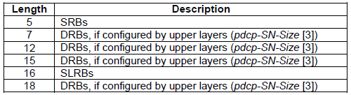
The limit applies to the SDU, so the PDCP PDU on the air is a little larger. The header adds 1 byte with a 5 or 7 bit SN, 2 bytes with a 12 or 15 bit SN, and 3 bytes with an 18 bit SN. An SRB PDU also carries the 4 byte MAC-I.
The same limit also applies to PDCP Control PDUs. For example, when a PDCP status report has many missing SDUs to report, the UE stops extending the Bitmap once the Control PDU reaches 8188 bytes, as 36.323 v19.0.0 clause 5.3.1 says.
8188 bytes in LTE, 1600 bytes in NB-IoT : for PDCP SDUs and for PDCP Control PDUs.PDCP does not segment : RLC segments PDCP PDUs, and an oversized IP packet is fragmented at the IP layer.The link MTU comes from PCO : the IPv4 Link MTU container 0010H of 24.008.
PDCP Data Structure
As in MAC PDU, RLC PDU.. PDCP also has it's own data structure and again you would never understand this structure in detail unless you get some real data and anlayze the data manually. But putting all together the following diagram (from 3GPP 36.323) would guide you to decode PDCP Data.
The only key question when you try to decode real PDCP data would be "Which diagram I have to use to decode this data ?". Only practice would give you the quick answer.
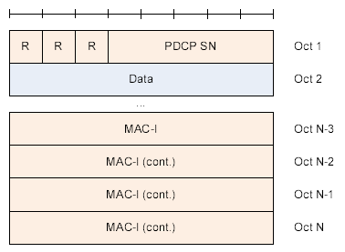
First Let's briefly look at the data structure. Following is the data structure for SRB. It means all the C plane data (RRC/NAS message) use this data structure. As you see, the first three bits are reserved. and next comes 5 bits PDCP SN(Sequence Number) and at the end of the block 4 bytes of MAC-I data is attached.
< 36.323 Figure 6.2.2.1 : PDCP Data PDU Format for SRBs >
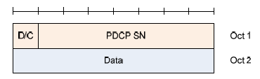
Following two diagram shows the PDCP structure for DRB. It means U-Plane data, DTCH data is using this kind of data structure. The only differences between these two data type is the size of SN (Sequence Number). One is using 7 bit and the other is 12 bits.
Comparing to SRB PDCP structure, you would find two differences. D/C bit at the first bit of the structure. This tells you whether the PDCP data is for user data or PDCP control data (This control data does not mean C-Plane data. It is control data being used in PDCP layer). And the other difference is that you do not have the MAC-I at the end of the data. MAC-I is the special information for Integrity protection. Do you remember Integrity Protection applies only to C-Plane data, not to U-Plane data ?
< 36.323 Figure 6.2.4.1 : PDCP Data PDU Format for DRBs using a 7 bit SN >
< 36.323 Figure 6.2.3.1 : PDCP Data PDU Format for DRBs using a 12 bit SN >
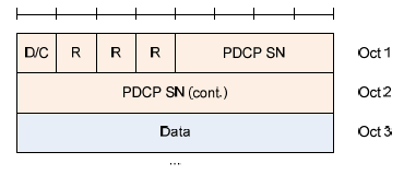
< 36.323 Figure 6.2.9.1: PDCP Data PDU format for DRBs using a 15 bit SN >
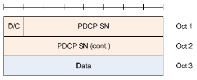
< 36.323 Figure 6.2.11.1: PDCP Data PDU format for DRBs using an 18 bit SN >
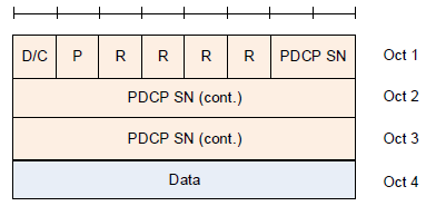
The 15 bit and 18 bit formats came later, with pdcp-SN-Size-v1130 in Release 11 and pdcp-SN-Size-v1310 in Release 13. Both are only for DRBs on RLC AM. The 18 bit format also carries a P bit. The eNB sets it in a downlink PDU to request a PDCP status report or an LWA status report. A UE that does not support LWA considers a PDU with P set to 1 invalid.
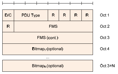
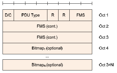
Following two data structure is a kind of PDCP layer control packet. Most of the LTE PDCP PDU you woud see would be the Data PDU. However, you may see the PDCP packet with D/C field = 0 (i.e, Control PDU) when PDCP PDU(s) get lost during the communication or you will often see these packets when ROHC is in action. In the case of missing PDCP packets, you would see Figure 6.2.6.1 structure and in ROHC case you would see Figure 6.2.5.1 structure as shown below.
< 36.323 Figure 6.2.5.1: PDCP Control PDU format for interspersed ROHC feedback packet >
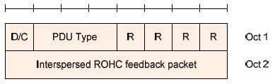
< 36.323 Figure 6.2.6.1: PDCP Control PDU format for PDCP status report using a 12 bit SN >
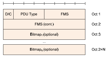
NOTE : FMS stands for First missing PDCP SN
< 36.323 Figure 6.2.6.2: PDCP Control PDU format for PDCP status report using a 15 bit SN >
< 36.323 Figure 6.2.6.3: PDCP Control PDU format for PDCP status report using an 18 bit SN >
All of the following tables shows the meaning of each data field shown in the diagrams we saw above. You will refer to this table a lot when you try to decode PDCP data yourself. Otherwise, you would read now and forget as your click to another page.
< 36.323 Table 6.3.2.1: PDCP SN length >
< 36.323 Table 6.3.7.1: D/C field >

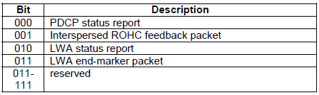
< 36.323 Table 6.3.8.1: PDU type >
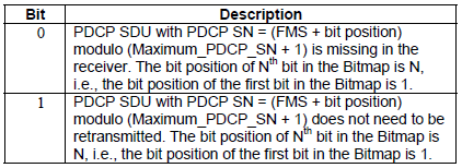
< 36.323 Table 6.3.10.1 Bitmap >
The PDU type table above is from Release 13. In 36.323 v19.0.0, value 100 is the UDC feedback packet and value 101 is the EHC feedback packet, so only 110 and 111 are reserved. The current specification also has formats that this page does not draw. These are the RN DRB PDU with MAC-I, the SLRB PDUs with a 16 bit SN, the LWA status report and end-marker, the UDC Data PDUs and the UDC and EHC feedback PDUs.
5 bit SN and MAC-I for SRBs : the MAC-I field is always there, padded with zeros when integrity protection is not active.D/C bit for DRBs : 1 for a Data PDU, 0 for a Control PDU.RRC sets the SN length : pdcp-SN-Size and its -v1130 and -v1310 extensions select 7, 12, 15 or 18 bits.PDU type identifies the Control PDU : status report, ROHC feedback, LWA, UDC or EHC feedback.
Integrity Protection Process
My perception of any process is "a black box that convert a set of inputs into a set of output". So for any process, I usually try to define what is the inputs and out is the final outputs.. and then try to find the all of the steps one by one to convert the input into the outputs.
If I define LTE Integrity Protection Procedure with this logic, it would be "a process that convert 'K' value from USIM into PDCP MAC-I and NAS MAC(Message Authentication Code)". Describing this process with illustration would be as follows. Just try to go through this illustration whenever you have chance and try to have your own idea first.
The process described here apply only to C-Plane data. Actually this is a huge topic and hard to be described here in detail (Refer to NAS Integrity page for further detail).
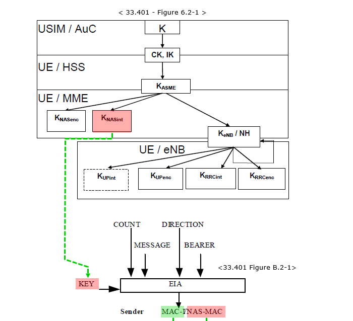
The diagram above joins two figures of 33.401. Figure 6.2-1 at the top is the key hierarchy, from K in the USIM down to the keys that the eNB uses. Figure B.2-1 at the bottom is the EIA algorithm, with its inputs COUNT, MESSAGE, DIRECTION, BEARER and KEY. The green dashed line follows the NAS case, where KNASint is the KEY. For PDCP, the KEY is KRRCint instead. The diagram below shows where the two outputs end up.
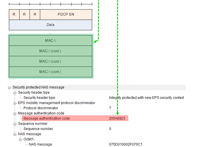
The MAC-I fills the last four octets of the PDCP Data PDU for an SRB. The NAS-MAC, 205A8923 in this capture, sits in the header of the security protected NAS message. The two values come from different keys and different COUNT values. So a NAS message inside an RRC message carries both of them, the NAS-MAC from the MME and the MAC-I from the eNB or the UE.
36.323 clause 5.7 lists the PDCP inputs. COUNT is the 32 bit PDCP COUNT, made of the HFN followed by the PDCP SN. BEARER is the radio bearer identity minus 1. DIRECTION is 0 for uplink and 1 for downlink. The protected data is the PDU header and the data part before ciphering. On an SRB, ciphering then covers the data part and the MAC-I together, as 36.323 clause 5.6 says.
At the receiver, PDCP computes the X-MAC with the same inputs and compares it with the received MAC-I. If they differ on SRB1 or SRB2, PDCP reports an integrity check failure to RRC. 36.331 v19.3.0 clause 5.3.7.2 then has the UE start RRC connection re-establishment. So a wrong KEY or a COUNT that is out of step between UE and eNB drops the connection, even when the radio link is good.
Five inputs give the MAC-I : KEY, COUNT, BEARER, DIRECTION and MESSAGE.KRRCint for PDCP, KNASint for NAS : the two MACs come from different keys and different COUNT values.Integrity first, then ciphering : on SRBs, the MAC-I is ciphered together with the data.EIA0 only for emergency calls : 33.401 allows it only for unauthenticated emergency calls.
Examples of PDCP Data Structure
Four PDUs from protocol logs show how the formats of the section above look in bytes. Each one is decoded by hand, from the PDCP header to the payload.
In this section, I will show you some of the examples of PDCP data structure.
Each example starts from the bytes that enter or leave PDCP, and the PDCP header is marked in red. The first three are Data PDUs, on DL DCCH, UL DCCH and DL DTCH. The last one is a Control PDU that carries ROHC feedback. Check the bearer type and the SN length first, because they decide which format from the section above applies.
Example : PDCP <-- DL DCCH : RRC Connection Reconfiguration
This is a downlink SRB PDU, so the 5 bit SN format with MAC-I applies. The RRC message starts with 20 in hex. In DL-DCCH-Message, that first byte selects rrcConnectionReconfiguration. The bytes decode directly as an RRC message, so this PDU was sent with null ciphering, like eea0 in the security mode captures above.
This example PDCP PDU has following structure. The SDU/PDU is from eNB PDCP.
PDCP bytes from a protocol log,
DL DCCH RRC : 20 06 03 59 3D 11 4D E1 B8 18 3A 10 17 00 30 00 07 88 80 00 08 01 B2 91 26 08 08 48 68 23 4B 73 2B A0 23 13 2B 63 60 13 1B 08 28 0E 05 40 08 09 38 DC 04 01 08 80 18 00 00 84 08 36 05 40 08 14 18 36 05 40 08 10 00 68 26 05 40 08 12 80 5F B0 07 88 84 00 08 00 00 00 00 08 98 07 88 80 00 09 18 2F A0 00 00 00 08 BF 02 CF 03 20 08 1F 93 53 E0 FA 81 BC 0F A8 E0 60 78 26 3E 9D 52 D2 E8 00 FB 50 65 03 FF 04 07 E8 10
PDCP PDU : 06 20 06 03 59 3D 11 4D E1 B8 18 3A 10 17 00 30 00 07 88 80 00 08 01 B2 91 26 08 08 48 68 23 4B 73 2B A0 23 13 2B 63 60 13 1B 08 28 0E 05 40 08 09 38 DC 04 01 08 80 18 00 00 84 08 36 05 40 08 14 18 36 05 40 08 10 00 68 26 05 40 08 12 80 5F B0 07 88 84 00 08 00 00 00 00 08 98 07 88 80 00 09 18 2F A0 00 00 00 08 BF 02 CF 03 20 08 1F 93 53 E0 FA 81 BC 0F A8 E0 60 78 26 3E 9D 52 D2 E8 00 FB 50 65 03 FF 04 07 E8 10 0C F3 6E 17
Header : 06 (Hex), 00000110 (Bin)
R - 0
R - 0
R - 0
SN - 00110 (Bin), 6 (Dec)
MAC-I : 0C F3 6E 17 // This is added by eNB PDCP Layer. UE is comparing this with the one it calculated internally.
Example : UL DCCH --> PDCP : RRC Connection Reconfiguration Complete
This is the uplink answer on SRB1. The log shows the RLC AM PDU, so the two byte RLC header A0 07 comes before the PDCP PDU. The PDCP header 07 gives SN 7. The RRC message 10 00 is an RRCConnectionReconfigurationComplete, because 10 in hex selects that message in UL-DCCH-Message.
This example PDCP PDU has following structure. The SDU/PDU is from UE PDCP.
PDCP bytes from a protocol log,
UL DCCH RLC : A0 07 07 10 00 C4 8E 9A A7
PDCP PDU : 07 10 00 C4 8E 9A A7
Header : 07 (Hex), 00000111 (Bin)
R - 0
R - 0
R - 0
SN - 00111 (Bin), 7 (Dec)
MAC-I : C4 8E 9A A7 // This is added by UEPDCP Layer. eNB is comparing this with the one it calculated internally.
Example : DL DTCH -> PDCP : IP Data
This is user plane data on a DRB with a 12 bit SN. The header is two bytes and there is no MAC-I. The SDU is a plain IPv4 packet that starts with 45, so neither ROHC nor ciphering was active on this bearer.
This example PDCP PDU has following structure. The SDU/PDU is from eNB PDCP.
PDCP bytes from a protocol log,
DL DTCH (from IP Interface) : 45 00 00 C8 04 12 40 00 80 11 72 BF C0 A8 01 02 C0 A8 01 01 EA 60 4A 12 00 B4 AE 8B 80 08 32 60 69 14 46 F2 18 69 D6 05 D5 57 57 D7 D3 55 57 5C 41 45 5E D6 DC D4 53 5E 5F 53 D6 D0 D2 DE D8 D0 55 56 D6 DE D0 D1 57 D4 54 54 57 5D 58 5C D5 D0 D2 55 D5 D6 54 51 55 D5 55 D4 D2 D3 D1 D5 51 5C D4 D9 D2 D5 51 5D 58 5E 56 DB DB 55 54 57 52 53 52 D7 D0 D0 D2 D6 55 D5 D1 D1 D3 D3 D7 D5 D4 53 53 50 55 D7 D5 55 57 57 52 54 56 56 50 56 54 D5 54 56 55 D1 D2 D1 DD D3 D3 DD D5 D3 D7 5E 5D 51 D6 DC D6 51 5D 58 5C D2 D2 D0 51 50 D4 52 54 D6 57 51 54 55 D4 D4 D6 50 D7 DF D7 D7 54 D2 DD D3 50 5B 5D 55 D7 D1 D7 D3
PDCP PDU : 80 48 45 00 00 C8 04 12 40 00 80 11 72 BF C0 A8 01 02 C0 A8 01 01 EA 60 4A 12 00 B4 AE 8B 80 08 32 60 69 14 46 F2 18 69 D6 05 D5 57 57 D7 D3 55 57 5C 41 45 5E D6 DC D4 53 5E 5F 53 D6 D0 D2 DE D8 D0 55 56 D6 DE D0 D1 57 D4 54 54 57 5D 58 5C D5 D0 D2 55 D5 D6 54 51 55 D5 55 D4 D2 D3 D1 D5 51 5C D4 D9 D2 D5 51 5D 58 5E 56 DB DB 55 54 57 52 53 52 D7 D0 D0 D2 D6 55 D5 D1 D1 D3 D3 D7 D5 D4 53 53 50 55 D7 D5 55 57 57 52 54 56 56 50 56 54 D5 54 56 55 D1 D2 D1 DD D3 D3 DD D5 D3 D7 5E 5D 51 D6 DC D6 51 5D 58 5C D2 D2 D0 51 50 D4 52 54 D6 57 51 54 55 D4 D4 D6 50 D7 DF D7 D7 54 D2 DD D3 50 5B 5D 55 D7 D1 D7 D3
Header : 80 48 (Hex) , 10000000 01001000 (Bin)
D/C - 1 // indicate that this is Data PDU
R - 0
R - 0
R - 0
SN - 0000 01001000 (Bin), 72 (Dec)
Following is the decoded IP Packet for your reference : (Blue and Pink part in the above PDU indicate Source and Destination IP address)
Decoded IP packet in Wireshark format,
Internet Protocol Version 4, Src: 192.168.1.2, Dst: 192.168.1.1
    0100 .... = Version: 4
    .... 0101 = Header Length: 20 bytes
    Differentiated Services Field: 0x00 (DSCP: CS0, ECN: Not-ECT)
        0000 00.. = Differentiated Services Codepoint: Default (0)
        .... ..00 = Explicit Congestion Notification: Not ECN-Capable Transport (0)
    Total Length: 200
    Identification: 0x0412 (1042)
    Flags: 0x02 (Don't Fragment)
        0... .... = Reserved bit: Not set
        .1.. .... = Don't fragment: Set
        ..0. .... = More fragments: Not set
    Fragment offset: 0
    Time to live: 128
    Protocol: UDP (17)
    Header checksum: 0x72bf [validation disabled]
        [Good: False]
        [Bad: False]
    Source: 192.168.1.2
    Destination: 192.168.1.1
    [Source GeoIP: Unknown]
    [Destination GeoIP: Unknown]
User Datagram Protocol, Src Port: 60000 (60000), Dst Port: 18962 (18962)
    Source Port: 60000
    Destination Port: 18962
    Length: 180
    Checksum: 0xae8b [validation disabled]
        [Good Checksum: False]
        [Bad Checksum: False]
    [Stream index: 0]
Data (172 bytes)
Example : ROHC Feedback
The last example is a PDCP Control PDU. The ROHC decompressor uses it to send feedback to the compressor on the other side. The PDCP header follows 36.323, but the payload follows the ROHC RFCs.
To decode the PDU in this example, 3GPP specification is not enough because this PDCP PDU contains ROHC feedback defined in RFC 4995 as shown below. (If you are interested only in PDCP header, 3GPP is enough .. but if you want to decode it a little bit further into the palyload of the PDU, you need to look into RFC 4995 in this case)
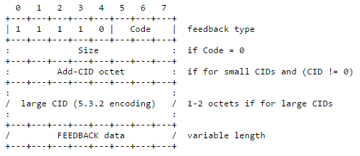
Code: 0 indicates that a Size octet is present.
1-7 indicates the size of the feedback data field, in octets.
Size: Indicates the size of the feedback data field, in octets.
FEEDBACK data: FEEDBACK-1 or FEEDBACK-2 (see below).
CID information in a feedback element indicates the context for which feedback is sent. The LARGE_CIDS parameter that controls whether a large CID is present is taken from the channel state of the receiving compressor's channel, not from the state of the channel carrying the feedback.
Following is an example of PDCP Control PDU captured during ROHC Operation.
PDCP bytes from a protocol log,
PDCP PDU : 10 F6 20 00 41 16 11 39 (HEX)
PDCP PDU : 00010000 11110110 00100000 00000000 01000001 00010110 00010001 00111001 (Bin)
Header : 10 F6 (Hex) , 00010000 11110110(Bin)
D/C - 0 // indicate that this is Control PDU
PDU Type - 001 // Indicate that this is Interspersed ROHC Feedback
R - 0
R - 0
R - 0
R - 0
Interspersed ROHC Feedback - 11110110 (Bin) // If you further decode this based on RFC, it goes as follows
11110 - Fixed in RFC4995
110 - Size of the feedback Data Field in Octets
The decode above stops at the Code field, so let's decode the remaining six octets, 20 00 41 16 11 39. With small CIDs and CID 0 there is no Add-CID octet, and with Code 6 there is no Size octet. Six octets are too many for FEEDBACK-1, so this is FEEDBACK-2. Assuming the context uses one of the RFC 3095 profiles, the format is RFC 3095 section 5.7.6.1.
20 = 00 10 0000 : Acktype 0 is ACK, Mode 2 is Bidirectional Optimistic mode, and the first 4 SN bits are 0000.00 : the next 8 SN bits, so the 12 bit SN is 0.41 16 : option type 4, the SN option, with length 1. It adds 8 more SN bits, 16 in hex.11 39 : option type 1, the CRC option, with length 1 and CRC 39 in hex.
So the decompressor acknowledges a packet and reports Bidirectional Optimistic mode. With the SN option, the SN it acknowledges is 0x016, which is 22.
06 and 07 are SRB headers : three R bits and the 5 bit SN, 6 and 7.80 48 is a DRB Data PDU : D/C 1 and the 12 bit SN 72.10 F6 is ROHC feedback : D/C 0, PDU type 001, and then the RFC 4995 feedback packet.A readable payload means no ciphering : all three Data PDUs show their payload in clear.
Reference
[1] 3GPP TS 36.323 v19.0.0 - clauses 4.3.1, 4.4, 5.6, 5.7, 6.2 and 6.3, PDCP functions, security and PDU formats
[2] 3GPP TS 36.331 v19.3.0 - PDCP-Config, SecurityAlgorithmConfig and the PDCP-Config field descriptions
[3] 3GPP TS 33.401 v19.2.0 - clause 5.1.4, Figure 6.2-1 and Annex B
[4] 3GPP TS 24.301 v20.0.0 - clause 5.4.3.2, NAS security mode control initiation by the network
[5] 3GPP TS 24.008 v20.0.0 - clause 10.5.6.3, Protocol configuration options, IPv4 Link MTU
[6] IETF RFC 4995 - The RObust Header Compression Framework, clause 5.2.4.1
[7] IETF RFC 3095 - RObust Header Compression, clause 5.7.6, feedback formats and options