|
IP/Network |
|||||||||||||||||||||||||||||||||||||||||||||||||||||||||||||||||||||||||||||||||||||||||||||||||||||||||||||||||||||||||||||||||||||||||||||||||||||||
|
IPv6
IPv6 is not a small topics at all and I am not the expert on this area to explain all the details of it. But I would like to share a couple of basic things on IPv6 which I think is important in mobile phone testing.
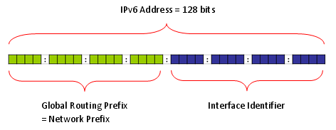
Anybody who is interested in IPv6 and read any IPv6 material would know IPv6 has 128 bits address space whereas IPv4 has 32 bit address space. There is one more thing you have to keep in mind expecially in relation to LTE. It is the fact that the IPv6 address is made up of two big chunks as follows. One of the chunk (the first 64 bits of address space) is called Network Prefix. The second chunk(the second 64 bits of the address space) is called 'Inferface Identifier'. The Network Prefix is called in many different name depending on the bit values assigned to this field. For example, sometimes it is called Site Local address and sometmes it is called Link Local address(Regarding the meaning of Site Local and Link Local adress, refer to the first two link at the end of this section. At least to me, they are the ones which explains the IPv6 address scheme in the easiest and the most intuitive manner).
As I mentioned above, "Network Prefix" part is called in many different name depeding on the bit values allocated to the field. Following shows the most frequently used Prefix.
If you capture the wireshark log during the test, you will see many different types of multicast address and this table would help you understand the meaning of those addresses. According to the table show above, all of the addresses in the following table represents Multicast address. As you see in the table, Multicast address has its own structure as shown in the table depending on the bit fields coming after the initial 'FF'.
Note : More details on Multicase prefix (Following description is quoted from http://computernetworkingnotes.com/ccna_certifications/ipv6_address_types_and_formats.htm)
For example, a multicast address that begins with FF02::/16 is a permanent link address, whereas an address of FF15::/16 is a temporary address for a site.
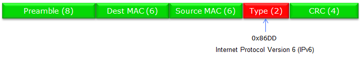
IPv6 is specially marked as follows in Ethernet Frame.( The number in (*) represents the number of bytes of each field)
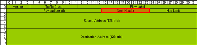
IPv6 IP Header and Next Header
IPv6 Packet (as in IPv4) can carry various types other packets (IPv6 Payload) and the type of these payload packet is marked in a special field called 'Next Header' as indicated below. Sometimes this "Next Header" field is called as 'Protocol Field".
There are many different types of Next Header, but I would put down only some of the field which you might see frequently.
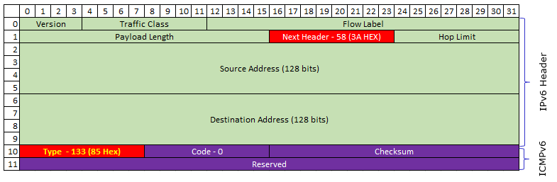
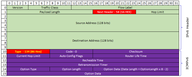
This is a generic description of IPv6 with the focus on the application to LTE. If everything goes well with this, just understanding overall procedure would be enough. But if you are in a position to do some troubleshooting or want to dig into the packet structure of IPv6, following illustration would be helpful. This is an example of IPv6 packet showing Ipv6 header and ICMPv6. There are many different types in ICMPv6 as listed here , but I will show you the most common two ICMPv6 packet structure - Router Solicitation and Router Advertisement message.
Following is the IPv6/ICMPv6 packet structure for Router Solicitation. As you see here, Next Header field of IPv6 header is set to be 58 (3A) and the Type field in ICMPv6 is set to be 133. (Refer to rfc4861 Router Solicitation Message Format for the formal description of each fields)
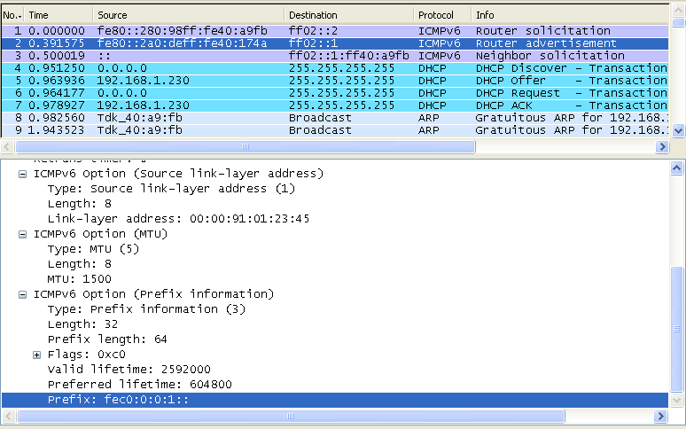
Following is the IPv6/ICMPv6 packet structure for Router Advertisement. As you see here, Next Header field of IPv6 header is set to be 58 (3A) and the Type field in ICMPv6 is set to be 134. Router Advertisement packet is much more complicated than Router Solicitation and this complication comes from the Option field. One Router Advertisement packet may have multiple Option field and the length of each option field can vary depending on option type. The length of each option field is specified in the length field of each option section. (Refer to rfc4861 4.2.Router Advertisement Message Format for the formal description of each fields)
One example of IPv6/Router Advertisement packet decoded by my personal Python script is as shown below. As you see, in this example there are three options .. but you may different number of options and different types of options depending on situations.
IPv6 Header ======================================================================= Version : 6 Traffic Class : 00000000(Bin) FlowLabel : 00000000000000000000(Bin) payloadLen : 64(Dec) Next Header : 58(Dec) : ICMPv6 Hop Limit : 255(Dec) Source Address : FE80:0:0:0:D1DE:AE75:2E92:1C33 Destination Address : FF02:0:0:0:0:0:0:1 Router Advertisement ========================================= Type : 134(Dec) : Router Advertisement (NDP) Code : 0(Dec) Checksum : 0x7399(HEX) Current Hop Limit : 0(Dec) AutoConfig Flag : 00000000(Bin) Router Life Time : 0(Dec) Reachable Time : 0(Dec) Retransmission Timer : 0(Dec) Link Address ---------------------------------------- (First Option) Type : 1(Dec) Length : 1(Dec) - 8 Bytes Link Address : 90:E2:BA:2D:C3:FE MTU ------------------------------------------------(Second Option) Type : MTU : 5(Dec) Length : 1(8 Bytes) Reserved : 0000(HEX) MTU : 1500(Dec) Prefix Information ------------------------------------(Third Option) Type : Prefix Information : 3(Dec) Length : 4(32 Bytes) Prefix Length : 64bits Flags : 11000000(BIN) Valid Lifetime : 2592000(Dec) Preferred Lifetime : 604800(Dec) Reserved : 00000000(HEX) Prefix Address : 2001:468:181:F100:0:0:0:0
Whenever you want to understand any form of packet structure, you would never understand it clearly unless you try to decode those packets by hand.Try decode the following examples of IPv6 packets according to the stucture as illustrated above.
Note : "Type" field in the structure shown above is showing "134" which means that this is for Router Advertisement. You will have different values in this field depending on the types of ICMPv6 messages.
Example : Router Solicitation (the HEX 85, Dec 134 at the array index 40 indicates it is Router Solicitation) 60 00 00 00 00 08 3A FF FE 80 00 00 00 00 00 00 00 00 00 00 01 01 00 02 FF 02 00 00 00 00 00 00 00 00 00 00 00 00 00 02 85 00 7C 34 00 00 00 00
Example : Router Advertisement(the HEX 86, Dec 135 at the array index 40 indicates it is Router Solicitation) 60 00 00 00 00 40 3A FF FE 80 00 00 00 00 00 00 02 1C 58 FF FE 7E 16 C9 FF 02 00 00 00 00 00 00 00 00 00 00 00 00 00 01 86 00 68 08 40 00 00 C8 00 00 00 00 00 00 00 00 01 01 00 1C 58 7E 16 C9 05 01 00 00 00 00 05 DC 03 04 40 C0 00 00 70 80 00 00 62 70 00 00 00 00 FD D3 C0 61 8C D7 85 C8 00 00 00 00 00 00 00 00
In most cases especially when there is no problem, you can do most of IP layer traffic analysis with Wireshark. But there are some cases where you cannot use Wireshark. On server side, there would be no problem to use Wireshark and capture all the packet. But on UE side, Wireshark would be able to capture any Packet unless UE completes the IP setup and in many case UE does not exposure it's interface unless it completes some specified procedure (like Router Solicitation / Router Advertisement). So if something happens in such early stages of IP transaction on UE side, you would not be able to analyze those IP packet with Wireshark on UE PC. In this case, you may have to turn to Network (Network Simulator) log or UE log and analyze the raw data of the IP packets manually. In this case, following table will help you a lot to identify what kind of packet it is. This is the table showing the meaning of the value in "Type" field of the IP packet structure shown above.
Types of ICMPv6. For more details, please refer to http://en.wikipedia.org/wiki/ICMPv6
Initial Transactions for IPv6 Connectivity
Following is the most common initial transactions for IPv6 connectivity. Router Discovery is performed whenever your IPv6 interface card boots up (refere to next section for details) and Neibour discovery would happen when you start the first data traffic (e.g, ping or UDP/TCP).
When you test your device with network simulator and a server PC directly connected to the network simulator, you may not have to care about this IPv6 process. But in some UE (in most of Verizon UEs as far as I experienced), UE would automatically send 'EMM : Detatch' request if it does not recieve any Router Advertisement within a certain time frame. So it would be good to understanding the basics of this Router Discovery process.
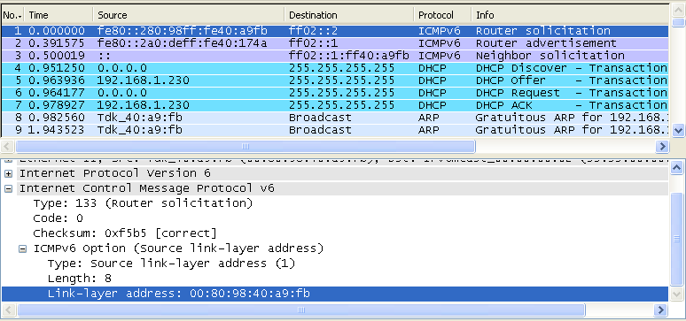
In IPv6, the user device (network interface card) automatically finds the router it is connected by using a special process called 'Router Discovery' process. You may think this is pretty similar to DHCP in IPv4. The basic idea of the process is simple. i) a Network device (user device) sends "Router Solicitation" packet to every body saying "I am a network interface device, please identify yourself if there is any router who is listening to me". ii) Router sends "Router Advertisement" packet saying "I am the router you are connected to and use this 'prefix' for any packets which should be delivered to outside networks".
Actually you can configure your router to send 'Router Advertisement' with a certain periodicity. But this periodicity (normally 10 seconds) can be too long in some case, in this case the host device (user device) can explicitely send 'Router Solicitation' and Router send 'Router Advertisement' .
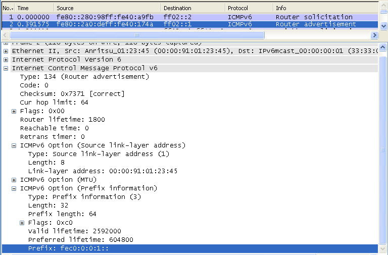
As shown in the following screenshot, a device informs all routers (ff02::2) of its Link-Layer address (MAC address) saying ""I am a network interface device with this MAC address, please identify yourself if there is any router who is listening to me"
The router that received "Router Solicitation" sends to all nodes (ff02::1), "I am the router you are connected to and use this 'prefix' for any packets which should be delivered to outside networks"
When you test your device with network simulator and a server PC directly connected to the network simulator, you may not have to care about this IPv6 process. As far as I experienced, there has been no problem even if I do nothing about this. But in some case, you will see a lot of additional negotiation processes in your wireshark log. One of the most frequently seen negotiation would be Neighbour Discovery process. Due to the curiosity of an engineer by nature, I decided to figure out the rough picture of this process at least.
Neighbor Discovery process has several different usages and depending on who (Router? or Host PC?) initiate the process, the purpose of the process can be different.
I found a good description of the purpose of ND(Neighbor Discovery) from msdn (http://msdn.microsoft.com/en-us/library/ms883129.aspx) as follows.
As you noticed, Neighbor Solicitation and Neighbor Adverdisement is used in several different situation and analyzing the packet log can be a little tricky. Making the practice of analyzing the various packet log (Wireshark log) would be a good way to understand this in detail.
Good Tutorials :
< Neighbor Solicitation >
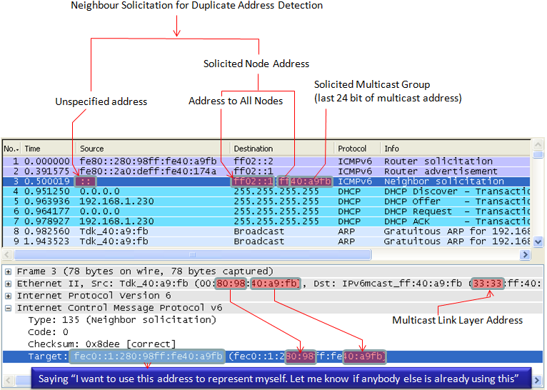
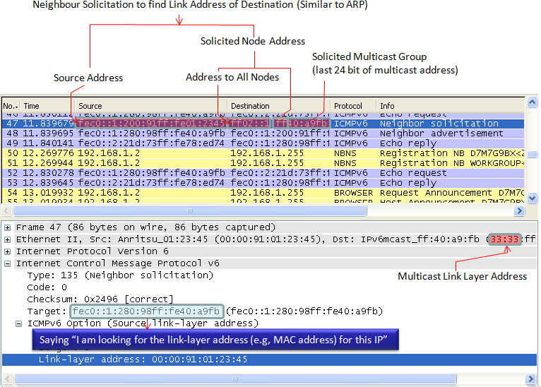
These messages have 3 main purposes. i) The first is to discover the link layer address of a neighbour as part of the address resolution process. This process replaces the use of ARP requests and replies in IPv4. ii) The second purpose is to determine the reachability of a neighbour. iii) The last is to detect the presence of duplicate IPv6 addresses during the address autoconfiguration process
Example 1 >
One example case where a Node (e.g, PC) send Neighbour Solicitation is to check if there is any other Node which uses the same IP address. Usually this message is sent before a Node fix (autoconfigures) its IP address. Basically this is to say "Hey.. everybody listen.. I want to use this IP for me, is there anybody who is currently use this IP ? If I don't hear any reply from anybody, I would use this IP for me". So if nobody send "Neighbour Advertisement", this Node use the IP.
Example 2 >
Next case where a Node (e.g, PC) send Neighbour Solicitation as for similar purpose as ARP in IPv4. Basically it is to say "I want to send something to this IP address, if there is anybody who has this IP, let me know the link layer address (MAC Address)". So in this case, the node should get the Neighbour Advertisement first to proceed next step.
< Neighbour Advertisement >
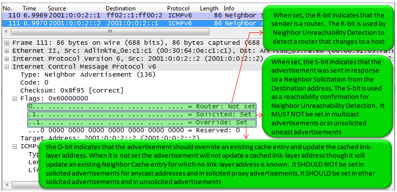
These messages are either in response to Neighbour Solicitations, or sent by a neighbour to announce a change in its link layer address. Upon receipt of a Neighbour Advertisement, a node will update its neighbour cache which contains mappings between IPv6 and link layer addresses of neighbours.
Since this neighbour discovery process happens in many different situations, it is very tricky to figure out the exact meaning when you get a Neighbour Advertisement message. In other words, it would not be easy to figure out right away to find out the answer to the questions like "Is this for Duplicate Address Detection ?", "Is this for Link Layer Address finding (like ARP) ?", "Is this for any other purpose ?". Unfortunately I haven't found any single line information in the message that gives me a clear answer. I need to check many different points in the message to figure out the purpose of the message. The option flag as described in RFC RFC 2461 4.4. Neighbor Advertisement Message Format and some examples in this sections are the points that I normally use. There would be some additional information that would give me even more clear answers and I will keep adding as I find more.
Example 1 >
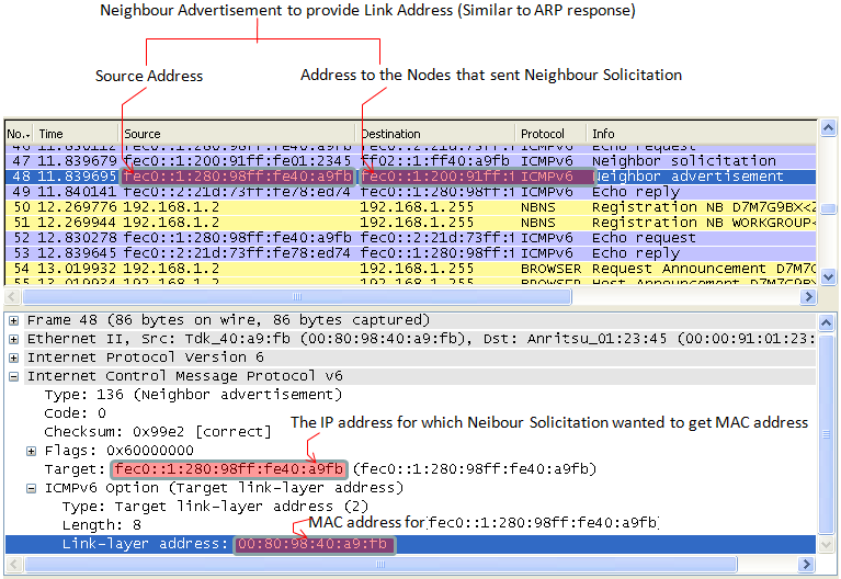
This examples shows the case where a Node send Neighbour Advertisement to provide 'Link Layer Address' in response to Neighbour Solicitation.
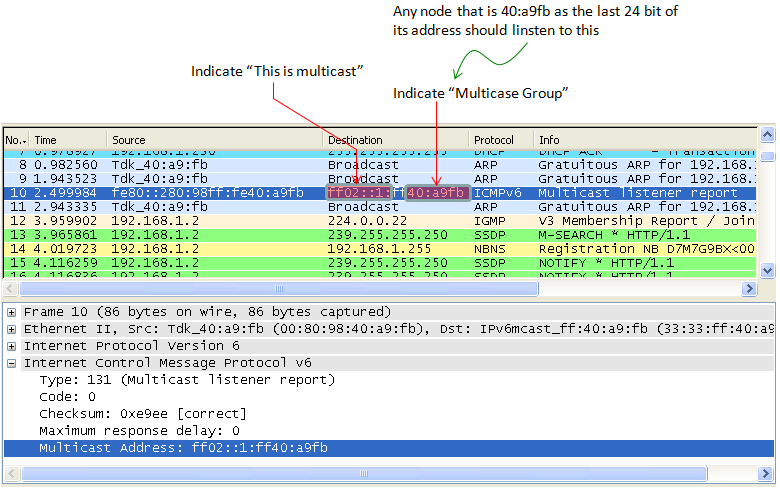
Multicast is "to send a packet from a single source to multiple destination simultaneosuly". For this, the group of the multiple destination which will receive the packet should be defined. Multicast Listener Discovery (MLD) is a specific IPv6 procedure to find and define the destination group that will receive the multicast packet.
PC to PC Connection Test - Case I
As in IPv4 test, the easiest way to learn and the best way for troubleshooting for IPv6 is to connect two PCs directly and try basic things.
Disclaimer : This tutorial may not work with your PC depending on the configuration and operating system that you are using. (For example, in Windows7 it seems that ping6 command is not supported and you have to use "ping -6". there may be some other differences that I haven't noticed).
I used the two PCs as follows and connect them directly each other using a Cat 6 ethernet cable.
PC A : Windows XP Professional Service Pack 3 PC B : Windows XP Professional Service Pack 2
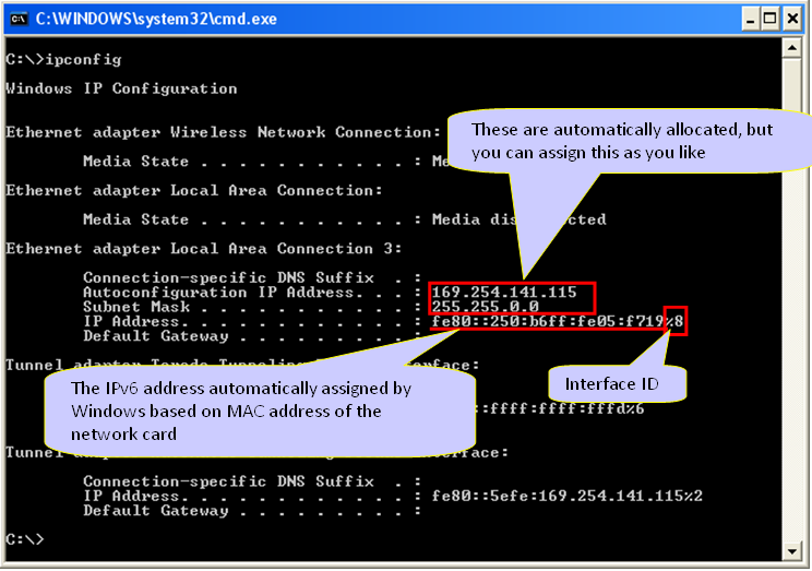
Following is the ipconfig result of my PC A. I have multile Ethernet cards in PC A and I will use the card labeled "Local Area Connection 3". I haven't specified any IPv4 address for this interface, but IPv4 address was automatically generated by IPv6 address allocation mechanism. (You may have 0.0.0.0 for Autoconfiguration IP Address and Subnet mask when you first connected the two PCs if you haven't specified it manually. But this IP would be configured automatically once you ping to other PC with IPv6. If you haven't set these IPv4 manually, the IP is set automatically to belong to the same subnet as the other PC). Note : For now, the IP Address that is assigned by the OS starts with fe80. Do you remember what kind of address is this ? (See 'Address Scheme' section for details). It is a Link Local Address which is a kind of private IP. At this point, this PC has only Link Local Address because it is not connected to any IPv6 router and I didn't perform any Router Discovery/Neighbour Discovery process.
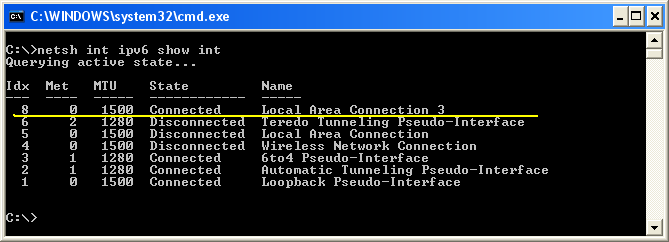
In IPv6 case, Inferface ID (Interface Index) of each ethernet card is important. You can figure out the interface ID for each network card using the command "netsh int ipv6 show int". The first column (labeled as "Idx") is the interface ID.
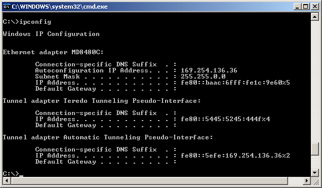
Following is the ipconfig result for PC B. I will use the ethernet card named MD8480C. I haven't specified any IPv4 address for this interface, but IPv4 address was automatically generated by IPv6 address allocation mechanism.
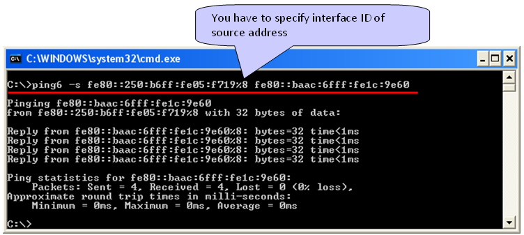
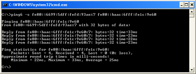
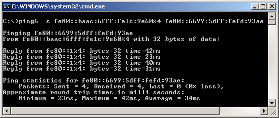
Now you have all the information ready for basic connection test, ping. Notice that I used the command "ping6" and specify the source address as well. The most difficult part of IPv6 ping test would be memorize and type the IP address -:)
Note : It is important to append interface ID to the source address especially when you have multiple ethernet inferface on the source PC. If you don't specify the interface ID, you may get the following errors.
Pinging fe80::baac:6fff:fe1c:9e60 from fe80::250:b6ff:fe05:f719 with 32 bytes of data:
Invalid source route specified. Problem with source address or scope-id. Invalid source route specified. Problem with source address or scope-id. Invalid source route specified. Problem with source address or scope-id. Invalid source route specified. Problem with source address or scope-id.
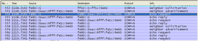
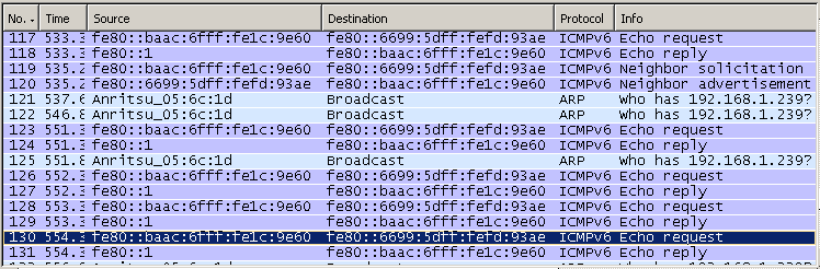
Ping statistics for fe80::baac:6fff:fe1c:9e60: Packets: Sent = 4, Received = 0, Lost = 4 (100% loss), If you don't have any error and capture Wireshark log, you will see a transaction as follows.
For the complete connection test, I always recommend you to try the other direction as well (ping from PC B to PC A), but I will not explain about it since the procedure is exactly same as above.
NOTE : If ping request (Echo Request) goes out from the source PC (verify with Wireshark on source PC) and comes into the target PC(verify with Wireshark on target PC), but Echo Reply (ping reply) does not issued by the target PC. A high possibility would be that target PC firewall is not allowing ICMP reply. I saw a lot of PCs configured this way.
PC to PC Connection Test - Case II
Following is another example for IPv6 test that I did at home using two PCs connected over WiFi access point (The ISP started supporing IPv6). This can be an easy and simple setup with which you can practice for IPv6.
< IP Configuration for one PC - Linux >
# ifconfig
eth0 Link encap:Ethernet HWaddr 08:9e:01:8c:15:be UP BROADCAST MULTICAST MTU:1500 Metric:1 RX packets:0 errors:0 dropped:0 overruns:0 frame:0 TX packets:0 errors:0 dropped:0 overruns:0 carrier:0 collisions:0 txqueuelen:1000 RX bytes:0 (0.0 B) TX bytes:0 (0.0 B) Interrupt:18
wlan0 Link encap:Ethernet HWaddr f4:b7:e2:9a:56:7b inet6 addr: fe80::f6b7:e2ff:fe9a:567b/64 Scope:Link UP BROADCAST MULTICAST MTU:1500 Metric:1 RX packets:482775 errors:0 dropped:0 overruns:0 frame:0 TX packets:280959 errors:0 dropped:0 overruns:0 carrier:0 collisions:0 txqueuelen:1000 RX bytes:658376982 (658.3 MB) TX bytes:29354535 (29.3 MB)
< IP Configuration for another PC - Windows 7 >
# ipconfig
Wireless LAN adapter Wireless Network Connection:
Connection-specific DNS Suffix . : Link-local IPv6 Address . . . . . : fe80::9154:c66f:8d0e:33cb%15 IPv4 Address. . . . . . . . . . . : 192.168.0.13 Subnet Mask . . . . . . . . . . . : 255.255.255.0 Default Gateway . . . . . . . . . : 192.168.0.1
< Ping from the Linux PC to Windows 7 PC >
# ping6 fe80::9154:c66f:8d0e:33cb -I wlan0 <-- In Linux(Ubuntus), you have to specify Interface ID using '-I'
PING fe80::9154:c66f:8d0e:33cb(fe80::9154:c66f:8d0e:33cb) from fe80::f6b7:e2ff:fe9a:567b wlan0: 56 data bytes
64 bytes from fe80::9154:c66f:8d0e:33cb: icmp_seq=2 ttl=128 time=109 ms 64 bytes from fe80::9154:c66f:8d0e:33cb: icmp_seq=3 ttl=128 time=10.8 ms 64 bytes from fe80::9154:c66f:8d0e:33cb: icmp_seq=4 ttl=128 time=34.0 ms 64 bytes from fe80::9154:c66f:8d0e:33cb: icmp_seq=7 ttl=128 time=89.4 ms
< Ping from the Windows 7 PC to the Linux PC>
# ping -6 fe80::f6b7:e2ff:fe9a:567b%15 <-- In Windows, you have to specify Interface ID using %
Pinging fe80::f6b7:e2ff:fe9a:567b%15 with 32 bytes of data: Reply from fe80::f6b7:e2ff:fe9a:567b%15: time=417ms Reply from fe80::f6b7:e2ff:fe9a:567b%15: time=237ms Reply from fe80::f6b7:e2ff:fe9a:567b%15: time=59ms
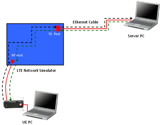
Before we get into the test procedure using a Network Simulator (UE tester), let's briefly look into the data path from the source to the destination. If you are in a position to test or troubleshoot IP related test, you'd better have logging tools to check the data flow of all these nodes. (High quality UE protocol log, Wireshark, High Quality Network Simulator logging tool would be a minimum requirement. Otherwise, you have to leave all those troubleshooting as a matter of luck). i) IP Client (e.g, ICMP-Ping) on UE PC ii) UE Packet Driver iii) UE LTE Protocol Stack iv) RF Channel v) LTE Network Simulator Radio Protocol Stack vi) TE port of Network Simulator vii) LAN Cable viii) LAN Card (NIC) on Server PC ix) IP Server(e.g, ICMP-Ping) on Server PC
If you do ping from UE PC to Server PC, the data path would be i) --> ii) --> iii) --> iv) --> v) --> vi) --> vii) --> viii) --> ix) : Echo Request ix) --> viii) --> vii) --> vi) --> v) --> iv) --> iii) --> ii) --> i) : Echo Reply We do ping (ping6) using the UE's IPv6 allocated by PC operating system (The one you get from 'ipconfig'). The ICMP client create a Echo Request ICMP packet with this IPv6 address. (I am not sure about this, but this is my observation) UE Packet Driver changes the source IP address that ICMP client assigned into the one the UE got from the NAS message (PDN Information). The remaining path is as you already know. If you see the Wireshark log on Server PC, you will see the IP address specified in the NAS message on Wireshark log. (This is different from what you typed in for ping6 command).
IPv6 Testing with Network Simulator
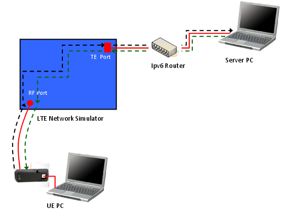
The configuration that I have used for this tutorial is as follows. Note that a server PC is directly connected to the equipment without using any router in the middle. So if a UE mandate to have Routing Advertisement as soon as it establishes EPS bearer, this test would not work. UE would disconnect EPS just a couple of seconds after it establishes EPS bearer in that case. But there would be such a UE which would not disconnect EPS even though it does not get Router Advertisement because there is possibility for direct/local connection.
For this tutorial, I used IPv4v6 dual stack. In this case, UE tend to remain connected even though it would not get Router Advertisement after EPS bearer setup. (But this also depends on UE implmentation).
In this test configuration, there are many different IP addresses you have to take into account. This is one of the biggest difficulties of IPv6 test. Followings are the list of IPv6 address involved in this setup.
i) Link Local address assigned by UE PC to the UE (You can get this from Ipconfig) ii) Link Local address created based on interface id in PDN address info iii) Destination IP address that the server PC is using when it reply to the packet from UE. iv) IP address to configure the TFT (Traffic Flow Template) of the TE port. (This would be the most tricky part).
You have to consider all of these IP addresses and have clear idea on how/when to use each of these IP addresses.
Let's try an example to show the complete process of this test.
< IP Config for UE PC >
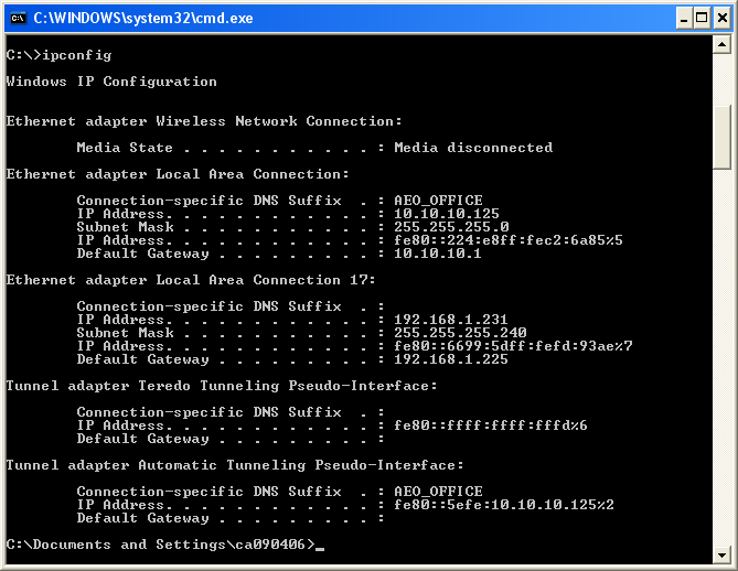
This is the ipconfig result for UE PC and "Ethernet Local Area Connection 17" is for the LTE UE when it is in Default EPS Bearer Connection with my LTE Network Simulator.
< IP Config for Server PC >
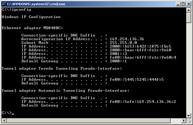
This is the ipconfig result for Server PC and "Ethernet adapter MD8480C" is the one that I will use. For now, disregard all IPv4 address and IPv6 address starting with 2000/2001. I will use the IP starting with fe80:: in this section.
< Interface ID on PDN - Activate Default EPS Bearer Context Request >
Following is the PDN address information that I set in Activate Default EPS Bearer Context Request. 0000000000000001 is the interface id for IPv6 and C0A891E7 is for IPv4.
+-PDN address ::= LV | +-Octet1 ::= DIVISION | | +-Length of PDN address contents ::= LEN (0..255) [13] | +-Octet2 ::= DIVISION | | +-spare ::= FIX [0] | | +-PDN type value ::= CHOICE [IPv4v6] | +-Octet3-14 ::= DIVISION | +-PDN address information ::= OCTETARRAY SIZE(0..12) [0000000000000001C0A891E7]
< TE Port filter Setting >
I configure the TFT (Traffic Flow Template) of the TE port of my BTS Emulator in such a way to allow the all incoming IP packet which has the destination address to be FE80::1 (FE80:0000:0000:0000:0000:0000:0000:0001). Exact way on how to configure this would vary with the equipment (BTS simulator).
You may need to go through some troubleshooting process to figure out which IP address you have to set for this TFT. Since this address may be different depending on the operating system and any IPv6 tools running the PC etc.
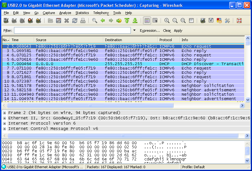
The way that I figure out this address is to capture Wireshark Log between the equipment TE port and Server PC and check the IP address for echo reply from the server. (If this TFT filter setting is wrong, the packet would not get into the equipment and reach the UE, but you can still get the packet from Wireshark running on the server PC). For example, following is the wireshark log captured on the server PC when I ping from UE PC to Server PC. The "echo reply" may not reach the UE depending on TFT settings, but you would get the destination address from this log. Configure your TFT filter so that I can allow the packets headed for the destination address.
< Ping from UE to Server PC >
Now we are ready for the ping. I did the ping from UE to Server PC as follows. Note that I used the UE's link local address that I got from ipconfig as a source address, not the address that I set in PDN address information.
Now let's look into Wireshark log for this transaction. There is no problem with Echo Request and Echo Reply. But don't you find any strage thing here ? If you see the source address of 'Echo request', it is different from the address that you specified in your ping command. It is the 'fe80:0000:0000:0000' (Network prefix for Link Local) + '0000:0000:0000:0001' (the interface ID you specified in PDN address info)'. It seems that the UE network driver translate the IP address you specified from ping command to this address. It imply that you would have different result for this depending on UE implementation.
< Ping from Server PC to UE >
Now let's ping from Server PC to UE to make it sure it works for both direction.
Following is the Wireshark log for this ping transaction. If you see 'Echo Request', Server PC does not do any IP translation for UE, but you would see UE is translating the IP in 'Echo Reply' to the one specified by PDN address information.
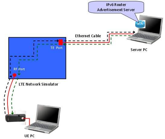
IPv6 Testing with Network Simulator and Router
There are some cases where UE must recieve Router Advertisement, otherwise it send EMM detach within a couple of seconds. In this case, you need to add proper tools to send the Router advertisement in response to the Router Solicitation from UE.
There are two ways to do this, one is to use a real IPv6 router and the other way is to use a special software which can send Router Advertisement.
As the first method, you can add an IPv6 router to the test equipment and connect the server PC to the router as follows. If you connect the test equipment to your company network. The configuration will be the most likely as follows. In this case, you have to know the details of Router configuration or have one of your IT people as a close friend -:)
Another way to do this is to use special software (program) simulating the IPv6 router and send 'Router Advertisement'. You can download such a software at http://sourceforge.net/projects/wradvs/ for windows XP and at http://www.litech.org/radvd/ for linux.
Overall test flow is similar to the case of direct connection, but there will some additional details you have to consider router setup/router software setup.
One of the biggest problem is to configure TFT filter on network (network emulator) side. Usually the network emulator would get through any packet from UE to out of the equipment, but they tend to apply very strict rule to incoming packets (Packets coming into the equipment). In case of Router Solicitation and Router Advertisement process, usually Router Solicitation would go through freely, but Router Advertisement would not get into the box unless you configure the IP filters at TE port. Then why don't we simply set the IP filter for it ? Unfortunately the answer is not easy mainly because there can be so many different combination of IP address for a same network interface.
Following is a Wireshark capture of IP packing captured at the TE port of an equipment.
Let's assume that we want to confiture the TE port (TFT filter) so that it allow Router Advertisement packet destined to the UE IP. What we have to do is simple and clear. Just to specify the proper UE IP address to TFT filter. But "How" part of this step is not so easy because there are too many different way of defining the UE IP address in this case.
What should be the one I have to use ? It is totally upto the network (network simulator) TE port implementation. so there would be no clear answer for it. (In case of the network simulator that I am using, I am supposed to use the type iii), but the answer would be different for your equipment).
There is even trickier case. In some equipment, the TFT filer works differently depending on whether the incomming packet is for Router Advertisement or it is for other generic packets (e.g, ping or ftp/udp etc). If the equipment support multiple TFT filter criteria you can simply set those multiple criteria, but if it is not the case you have to change TFT filter configuration after you complete Router Solicitation / Router Advertisement.
Configuring Windows XP to simulate IPv6 Router
As I mentioned above, you can make WindowsXP to work as IPv6 router. By doing this, you can do the basic IPv6 testing without using any hardware IPv6 router.
The way to do this is to use special software (program) simulating the IPv6 router and send 'Router Advertisement'. You can download such a software at http://sourceforge.net/projects/wradvs/ for windows XP and at http://www.litech.org/radvd/ for linux.
Configuring Windows 7 to simulate IPv6 Router
In Windows 7, you can make the operating system to act as IPv6 router without installing any additional software. You only have to execute the following three netsh command.
i) netsh interface ipv6 set interface [Interface ID] advertise=enabled Ex> netsh interface ipv6 set interface 11 advertise=enabled
ii) netsh interface ipv6 add route [Prefix/64] [Interface ID] publish=yes Ex> netsh interface ipv6 add route 2001:0:0:2::/64 11 publish=yes
iii) netsh interface ipv6 set interface [Interface ID] currenthoplimit=64 Ex> netsh interface ipv6 set interface 11 currenthoplimit=64
Reference :
Followings are the link where you can get some basic understaqnding of IPv6.
|
|||||||||||||||||||||||||||||||||||||||||||||||||||||||||||||||||||||||||||||||||||||||||||||||||||||||||||||||||||||||||||||||||||||||||||||||||||||||