A signalling log reads like a list of separate messages, but many of those messages depend on each other. A value that one message carries often has to come back in a later message, or the later step fails. This page follows those links through one registration on a UMTS cell, first in the RRC layer and then in the NAS layer. When a registration breaks in the middle, these links tell you which earlier message to check first. They also tell you which values a test setup has to keep consistent.
- Which values does one message pass to another ?
- How does the RRC layer check the links ?
- How does the NAS layer reuse identities and keys ?
- Reference
Which values does one message pass to another ?
Let's start from the whole sequence, because each link only makes sense next to the step that uses the value. The sequence is one registration in both the CS domain and the PS domain, run the way a test system usually runs it. Both registrations share one RRC connection, so the CS messages come first and the PS messages follow.
The diagram below has three vertical lines. The UE is on the left, the cell is in the middle and the USIM is on the right. The black arrows are the messages, and the logical channel of each message is written after its name. The red lines are the correlations. On the right side, a red line runs from the place where a value comes from to the message that has to carry it again. On the left side, a red arrow leaves the UE line at a message that produces a value for later use.
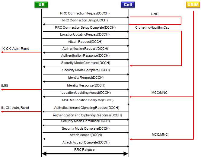
Five values tie the registration together: the initial UE identity, the ciphering algorithm capability, the authentication keys, the IMSI and the PLMN code.
UeID : The identity in RRC Connection Request has to come back in RRC Connection Setup. The next section explains why the UE checks it.CipheringAlgorithmCap : The UE reports its security capability in RRC Connection Setup Complete. The network has to repeat it in Security Mode Command, and it can only select algorithms from it.IK, CK, Autn, Rand : Each authentication gives a RAND and an AUTN to the UE, and the USIM computes a new CK and IK from them. The Security Mode Command that follows starts ciphering and integrity protection with those keys.IMSI : The UE gives its permanent identity in Identity Response when the network asks for it.MCC/MNC : The PLMN code in Location Updating Accept and in Attach Accept is drawn from the USIM. This means the cell is set up as the home network of the test USIM.Two security runs : The CS domain and the PS domain each run their own authentication and their own Security Mode Command. The PS run uses Authentication and Ciphering Request and Response.
Two labels in the diagram differ from the specification. "Authetication and Ciphering Request" is a typo for Authentication and Ciphering Request. "Attach Accept Complete" is the message that 24.008 calls ATTACH COMPLETE. In the same way, TMSI Reallocation Complete here answers the new TMSI in Location Updating Accept, and no separate TMSI Reallocation Command is sent.
Correlations cross layers : A value from an RRC message can be checked in a later RRC message, and a value from the USIM can show up in a NAS message.Each domain has its own key set : The CS keys and the PS keys come from separate authentications, so a problem in one domain does not have to show in the other.
How does the RRC layer check the links ?
Two of the links live inside the RRC layer. The UE checks both of them itself, and a mismatch in either one stops the procedure. So when a UE seems to ignore a message from the network, these two checks are the first place to look.
The first link is the initial UE identity. The UE puts the IE "Initial UE identity" into RRC CONNECTION REQUEST. The UE chooses it by the rules in 25.331 subclause 8.5.1, and the choice covers an IMSI, a TMSI and LAI, a P-TMSI and RAI or an IMEI, among others. RRC CONNECTION SETUP comes back on the CCCH, and other UEs in the cell can also receive the CCCH. So the network copies the identity into the setup message, and the UE compares it with its variable INITIAL_UE_IDENTITY. If the two values are different, the UE ignores the rest of the message (25.331 subclause 8.1.3.6). The UE then waits for T300 to expire and sends a new RRC CONNECTION REQUEST, as long as V300 has not passed N300.
The second link is the security capability. In RRC CONNECTION SETUP COMPLETE the UE reports its radio access capability, and the IE "Security capability" is part of it. That IE lists the ciphering algorithms UEA0, UEA1 and UEA2 and the integrity algorithms UIA1 and UIA2 (25.331 subclause 10.3.3.37). The UE stores what it sent in the variable UE_CAPABILITY_TRANSFERRED. SECURITY MODE COMMAND then carries the IE "Security capability" as a mandatory IE. The UE compares it with UE_CAPABILITY_TRANSFERRED, and it does the same for the GSM security capability when the network includes one.
Why does the network have to echo the capability? RRC CONNECTION SETUP COMPLETE goes out before integrity protection starts, so an attacker could change it. SECURITY MODE COMMAND is integrity protected. So the echo lets the UE confirm that the network saw the true capability. If the values differ, the UE releases all its radio resources and enters idle mode (25.331 subclause 8.1.12.3).
A wrong UeID looks like a lost setup : The UE ignores the setup silently and repeats the request after T300, so the log shows repeated RRC Connection Requests.A wrong security capability drops the call : The UE leaves connected mode right after Security Mode Command, without sending Security Mode Complete.The network selects from the UE list : The UEA and UIA values in Ciphering mode info and Integrity protection mode info have to be ones the UE reported.
How does the NAS layer reuse identities and keys ?
The remaining links run through the NAS layer and the USIM. They decide whether the UE and the network end up with the same identity, the same keys and the same location. A test system has to keep all of them consistent with the USIM it uses.
Let's take the keys first. AUTHENTICATION REQUEST carries RAND and, for a UMTS challenge, AUTN. The USIM checks AUTN to authenticate the network. It then returns RES and computes a new UMTS ciphering key CK and a new UMTS integrity key IK (24.008 subclause 4.3.2). The network holds the same CK and IK from the authentication vector. The ciphering key sequence number in AUTHENTICATION REQUEST names this key set. So the SECURITY MODE COMMAND that follows can start ciphering and integrity protection with keys that both sides already have. The PS domain repeats the same steps with AUTHENTICATION AND CIPHERING REQUEST, so the PS domain gets its own CK and IK.
Next come the identities. The network sends IDENTITY REQUEST when it needs the IMSI, and the UE answers with IDENTITY RESPONSE. The accept messages then give the UE a temporary identity. When LOCATION UPDATING ACCEPT contains a TMSI, the UE stores it in the USIM and answers with TMSI REALLOCATION COMPLETE (24.008 subclause 4.4.4.6). When ATTACH ACCEPT contains a P-TMSI, the UE uses it for GPRS services and answers with ATTACH COMPLETE. The network starts T3250 for the TMSI and T3350 for the P-TMSI, and it stops each timer when the matching complete message arrives.
Finally, the location. LOCATION UPDATING ACCEPT carries the LAI, and the UE stores it and sets its update status to UPDATED. ATTACH ACCEPT carries the RAI in the same way. Both LAI and RAI start with the MCC and MNC. In the diagram these codes come from the USIM, so the UE sees the cell as its home PLMN. When the MCC and MNC of the cell do not match the USIM, the UE treats the cell as another PLMN, and PLMN selection and roaming rules apply.
Security Mode Command depends on authentication : The keys it activates come from the last authentication in the same domain, so a failed authentication means no ciphering.Every new temporary identity needs a complete message : A missing TMSI Reallocation Complete or Attach Complete leaves the network holding both the old and the new identity.The PLMN code has to match the USIM for a home network test : Otherwise the UE applies roaming rules, and the test no longer measures what it was set up for.
Reference
- 3GPP TS 25.331 v19.0.1 : Radio Resource Control (RRC); Protocol specification
- 3GPP TS 24.008 v20.0.0 : Mobile radio interface Layer 3 specification; Core network protocols; Stage 3