DRX stands for "Discontinous Reception" and DTX stands for "Discontinous Transmission". When you are talking about 'Reception' and 'Transmission', you may often get confused with 'direction of data flow'. Is it from 'UE to Network' or 'Network to UE'. At least, I got confused so often with this.
So let's make it clear about 'who is receiving ?' and 'who is transmitting' when we are talking about DRX and DTX. The answer is 'UE'. Therefore, DRX means 'Discontinous Reception by UE' and DTX means 'Discontinous Transmission by UE'.
On this page, DTX and DRX mean the Continuous Packet Connectivity, CPC, features of Release 7 for a UE in CELL_DCH. The UE keeps its HSDPA and HSUPA connection, but it stops sending the uplink DPCCH and stops monitoring the HS-SCCH in most subframes. This is different from the paging DRX that a UE uses in idle mode, CELL_PCH and URA_PCH.
The page first explains why DTX and DRX exist. It then reads a real configuration, and finally walks through the uplink and the downlink operation.
- Why does the UE need DTX and DRX ?
- Which parameters configure DTX and DRX ?
- How does uplink DTX work ?
- How does downlink DRX work ?
- Reference
Why does the UE need DTX and DRX ?
Then what does it mean by 'Discontinous' ? To get clear understanding of this word, let's think about 'what does it mean by 'continous' ?'. 'Continous' is a ordinary mode of operation in most of the situation where we use mobile phone. Does 'Continous' mean that UE is continously (always) receiving some data and is continously (always) transmitting data ? No, it does not. UE cannot receive any data when Network does not send any data to it and UE cannot transmit any data when it does not have any data to send. 'Continuous transmission/Continuous Reception' in this context mean that 'UE is continuously (always) ready to recieve data and is continously (always) ready to transmit the data.
To be ready to recieve/transmit something, UE should be 'ON'. So Continous reception/Continous transmission means that "UE is always ON(Wake-up mode)".
What's wrong with UE being always 'ON'. You many easily figure out that it will cause a lot of battery consumption.
To save this kind of battery consumption, they invented a special mechanism called 'Discontinous Reception/Transmission'. 'Discontinous Transmission' and 'Discontinous Reception' means that UE is in Sleeping Mode most of the time and only periodically 'Wake up' to receive or transmit the data.
Battery is only one reason. Every UE in CELL_DCH sends its uplink DPCCH continuously, even when it has no data, and each DPCCH adds to the uplink interference of the cell. When many UEs stay in CELL_DCH without data, this control overhead limits how many of them the cell can hold. With DTX, a UE without data sends the DPCCH only in short bursts, so the cell can keep more UEs in CELL_DCH. Those UEs can then restart a data transfer at once, without first moving back from CELL_FACH or CELL_PCH.
For CPC, the UE and the Node B must agree on the moments when the UE is awake. So the pattern is fixed by RRC parameters rather than decided by the UE alone. The UE uses DTX and DRX only in CELL_DCH with HS-DSCH and E-DCH configured. Unless DCH enhancements are configured, there is also no uplink DPDCH, and the downlink uses F-DPCH. In that state the uplink DPCCH carries no user data, so the UE can stop it in most slots.
Both DTX and DRX are done by the UE : DTX stops the uplink DPCCH, and DRX stops the HS-SCCH monitoring.CPC works inside CELL_DCH : the UE keeps its HSPA connection and saves battery between bursts of data.The pattern is shared with the network : the Node B knows when the UE is awake, because both sides use the same RRC parameters.
Which parameters configure DTX and DRX ?
Overall concept would sound simple, but you may get confiused again trying to understand the detailed parameter related to DTX and DRX. These parameters are specified in Radio Bearer Message as follows.
First I thought we only need 'Periodicity of DTX/DRX' and 'Duration of ON time', but there are many other parameters are involved.
Decoded RRC message from a tester log,
     | +-dtx-drx-TimingInfo ::= SEQUENCE OPTIONAL:Exist
     | | +-timing ::= CHOICE [newTiming]
     | |   +-newTiming ::= SEQUENCE
     | |     +-enablingDelay ::= ENUMERATED [radio-frames-0]
     | |     +-ue-dtx-drx-Offset ::= INTEGER (0..159) [0]
     | +-dtx-drx-Info ::= SEQUENCE [11] OPTIONAL:Exist
     | | +-dtx-Info ::= SEQUENCE [01] OPTIONAL:Exist
     | | | +-e-dch-TTI-Length ::= CHOICE [dtx-e-dch-TTI-10ms]
     | | | | +-dtx-e-dch-TTI-10ms ::= SEQUENCE
     | | | |   +-ue-dtx-Cycle1-10ms ::= ENUMERATED [sub-frames-10]
     | | | |   +-ue-dtx-Cycle2-10ms ::= ENUMERATED [sub-frames-20]
     | | | |   +-mac-dtx-Cycle-10ms ::= ENUMERATED [sub-frames-10]
     | | | +-ue-dtx-cycle2InactivityThreshold ::= ENUMERATED [e-dch-tti-8]
     | | | +-ue-dtx-cycle2DefaultSG ::= INTEGER OPTIONAL:Omit
     | | | +-ue-dtx-long-preamble-length ::= ENUMERATED [slots-4] OPTIONAL:Exist
     | | | +-mac-InactivityThreshold ::= ENUMERATED [e-dch-tti-8]
     | | | +-cqi-dtx-Timer ::= ENUMERATED [sub-frames-32]
     | | | +-ue-dpcch-Burst1 ::= ENUMERATED [sub-frames-1]
     | | | +-ue-dpcch-Burst2 ::= ENUMERATED [sub-frames-1]
     | | +-drx-Info ::= SEQUENCE OPTIONAL:Exist
     | | | +-ue-drx-Cycle ::= ENUMERATED [sub-frames-10]
     | | | +-ue-drx-Cycle-InactivityThreshold ::= ENUMERATED [sub-frames-32]
     | | | +-ue-GrantMonitoring-InactivityThreshold ::= ENUMERATED [e-dch-tti-8]
     | | | +-ue-drx-GrantMonitoring ::= BOOLEAN [TRUE]
     | | +-uplink-DPCCHSlotFormatInformation ::= ENUMERATED [slot-format-1]
The capture has two parts. The IE dtx-drx-TimingInfo tells the UE when to start, and the IE dtx-drx-Info holds the patterns themselves. With enablingDelay = radio-frames-0, the UE may start DTX and DRX at once, without a period of continuous DPCCH. With ue-dtx-drx-Offset = 0, the patterns start where 5 x CFN + subframe number is a multiple of the cycle length.
Most values are counted in subframes of 2 ms, even when the E-DCH TTI is 10 ms. The inactivity thresholds for DTX and for the MAC are counted in E-DCH TTIs instead, so e-dch-tti-8 means 80 ms in this capture. The table below maps each IE to the parameter name used in 25.214 and 25.321.
RRC IE in the capture |
Name in 25.214 or 25.321 |
Meaning |
Value in the capture |
ue-dtx-Cycle1-10ms |
UE_DTX_cycle_1 |
Uplink DPCCH burst pattern length while E-DCH is active, in subframes |
sub-frames-10, 20 ms |
ue-dtx-Cycle2-10ms |
UE_DTX_cycle_2 |
Burst pattern length after the inactivity threshold, in subframes |
sub-frames-20, 40 ms |
mac-dtx-Cycle-10ms |
MAC DTX Cycle |
Grid of TTIs at which a new E-DCH transmission may start after inactivity |
sub-frames-10, 20 ms |
ue-dtx-cycle2InactivityThreshold |
Inactivity_Threshold_for_UE_DTX_cycle_2 |
E-DCH TTIs without E-DCH transmission before cycle 2 applies |
e-dch-tti-8, 80 ms |
ue-dtx-long-preamble-length |
UE_DTX_long_preamble_length |
DPCCH preamble in slots before E-DCH or CQI after inactivity, 2 slots when absent |
slots-4 |
mac-InactivityThreshold |
MAC Inactivity Threshold |
E-DCH TTIs without E-DCH transmission before the MAC DTX cycle applies |
e-dch-tti-8, 80 ms |
cqi-dtx-Timer |
CQI_DTX_TIMER |
Subframes during which CQI reports have priority over the DTX pattern |
sub-frames-32 |
ue-dpcch-Burst1, ue-dpcch-Burst2 |
UE_DPCCH_burst_1, UE_DPCCH_burst_2 |
DPCCH burst length in cycle 1 and in cycle 2, in subframes |
sub-frames-1, 2 ms |
ue-drx-Cycle |
UE_DRX cycle |
HS-SCCH reception pattern length, in subframes |
sub-frames-10, 20 ms |
ue-drx-Cycle-InactivityThreshold |
Inactivity_Threshold_for_UE_DRX_cycle |
Subframes of continuous HS-SCCH monitoring after an HS-SCCH or HS-PDSCH reception |
sub-frames-32 |
ue-GrantMonitoring-InactivityThreshold |
Inactivity Threshold for UE Grant Monitoring |
E-DCH TTIs of full E-AGCH and E-RGCH monitoring after a scheduled E-DCH transmission |
e-dch-tti-8 |
ue-drx-GrantMonitoring |
UE_DRX_Grant_Monitoring |
Whether the UE monitors E-AGCH, E-ROCH and E-RGCH at the HS-SCCH reception subframes |
TRUE |
25.331 also checks the values against each other. The UE behaviour is unspecified if UE DTX cycle 2 is not an integer multiple of UE DTX cycle 1, or if a DPCCH burst is longer than its cycle. The same is true if UE DRX cycle is not a multiple or a divisor of UE DTX cycle 1. It is also true if UE DTX cycle 1 is not a multiple or a divisor of MAC DTX cycle. The capture passes all of these checks. UE DTX cycle 2 is twice UE DTX cycle 1, both bursts are 1 subframe, and the other three cycles are all 10 subframes.
The ASN.1 below is the current definition of the same IEs. The capture uses the Release 7 structure DTX-DRX-Info-r7, which is still valid. The newer DTX-DRX-Info-r12 adds DTX parameters for a secondary uplink frequency, and DRX-Info-r12 adds a second DRX cycle, ue-drx-Cycle2, with its own inactivity threshold.
Following is based on
DTX-DRX-TimingInfo-r7 ::=			SEQUENCE {
	timing								CHOICE {
		continue							NULL,
		newTiming							NewTiming
	}
}

NewTiming ::=						SEQUENCE {
	enablingDelay						EnablingDelay,
	ue-dtx-drx-Offset					UE-DTX-DRX-Offset
}

UE-DTX-DRX-Offset ::=					INTEGER (0..159)

DTX-DRX-Info-r7 ::=					SEQUENCE {
	dtx-Info							DTX-Info							OPTIONAL,
	drx-Info							DRX-Info							OPTIONAL,
	uplink-DPCCHSlotFormatInformation	Uplink-DPCCH-Slot-Format-Information
}

DTX-DRX-Info-r12 ::=					SEQUENCE {
	dtx-Info							DTX-Info							OPTIONAL,
	dtx-Info-SecondaryUplinkFrequency	DTX-Info-SecondaryUplinkFrequency	OPTIONAL,
	drx-Info							DRX-Info-r12						OPTIONAL,
	uplink-DPCCHSlotFormatInformation	Uplink-DPCCH-Slot-Format-Information
}

DTX-Info ::=						SEQUENCE {
	e-dch-TTI-Length					CHOICE {
		dtx-e-dch-TTI-10ms					DTX-E-DCH-TTI-10ms,
		dtx-e-dch-TTI-2ms					DTX-E-DCH-TTI-2ms
	},
	ue-dtx-cycle2InactivityThreshold	UE-DTX-Cycle2InactivityThreshold,
	ue-dtx-cycle2DefaultSG				INTEGER (0..38)						OPTIONAL,
	-- if ue-dtx-long-preamble-length is not present, the value is '2 slots'
	ue-dtx-long-preamble-length			UE-DTX-long-preamble-length			OPTIONAL,
	mac-InactivityThreshold				MAC-InactivityThreshold,
	cqi-dtx-Timer						CQI-DTX-Timer,
	ue-dpcch-Burst1						UE-DPCCH-Burst,
	ue-dpcch-Burst2						UE-DPCCH-Burst
}

DTX-E-DCH-TTI-10ms ::=				SEQUENCE {
	ue-dtx-Cycle1-10ms					UE-DTX-Cycle1-10ms,
	ue-dtx-Cycle2-10ms					UE-DTX-Cycle2-10ms,
	mac-dtx-Cycle-10ms					MAC-DTX-Cycle-10ms
}

DTX-E-DCH-TTI-2ms ::=				SEQUENCE {
	ue-dtx-Cycle1-2ms					UE-DTX-Cycle1-2ms,
	ue-dtx-Cycle2-2ms					UE-DTX-Cycle2-2ms,
	mac-dtx-Cycle-2ms					MAC-DTX-Cycle-2ms
}

UE-DTX-Cycle1-10ms ::=				ENUMERATED {
										sub-frames-1,
										sub-frames-5,
										sub-frames-10,
										sub-frames-20 }

UE-DTX-Cycle2-10ms ::=				ENUMERATED {
										sub-frames-5,
										sub-frames-10,
										sub-frames-20,
										sub-frames-40,
										sub-frames-80,
										sub-frames-160,
										spare2,
										spare1 }

MAC-DTX-Cycle-10ms ::=				ENUMERATED {
										sub-frames-5,
										sub-frames-10,
										sub-frames-20,
										spare1 }

UE-DPCCH-Burst ::=					ENUMERATED {
										sub-frames-1,
										sub-frames-2,
										sub-frames-5,
										spare1 }

DRX-Info ::=						SEQUENCE {
	ue-drx-Cycle						UE-DRX-Cycle,
	ue-drx-Cycle-InactivityThreshold	UE-DRX-Cycle-InactivityThreshold,
	ue-GrantMonitoring-InactivityThreshold
										UE-GrantMonitoring-InactivityThreshold,
	ue-drx-GrantMonitoring				BOOLEAN
}

DRX-Info-r12 ::=					SEQUENCE {
	ue-drx-Cycle						UE-DRX-Cycle,
	ue-drx-Cycle2						UE-DRX-Cycle2						OPTIONAL,
	ue-drx-Cycle-InactivityThreshold	UE-DRX-Cycle-InactivityThreshold,
	ue-drx-Cycle2-InactivityThreshold	UE-DRX-Cycle-InactivityThreshold	OPTIONAL,
	ue-GrantMonitoring-InactivityThreshold
										UE-GrantMonitoring-InactivityThreshold,
	ue-drx-GrantMonitoring				BOOLEAN
}

UE-DRX-Cycle ::=					ENUMERATED {
										sub-frames-4,
										sub-frames-5,
										sub-frames-8,
										sub-frames-10,
										sub-frames-16,
										sub-frames-20,
										spare2,
										spare1 }
Two IEs configure CPC : DTX-DRX timing information says when to start, and DTX-DRX information holds the patterns.Cycles and bursts are in 2 ms subframes : the DTX and MAC inactivity thresholds are in E-DCH TTIs.The cycles must fit together : cycle 2 is a multiple of cycle 1, and the DRX and MAC DTX cycles are multiples or divisors of UE DTX cycle 1.
How does uplink DTX work ?
Now let's look into the detailed parameters. Let's think about DTX part first. (I will draw some diagram later when I have more time, but now I will just describe it verbally). The most important parameters for DTX are as follows.
Excerpt of the same capture,
     | | | +-e-dch-TTI-Length ::= CHOICE [dtx-e-dch-TTI-10ms]
     | | | | +-dtx-e-dch-TTI-10ms ::= SEQUENCE
     | | | |   +-ue-dtx-Cycle1-10ms ::= ENUMERATED [sub-frames-10]
     | | | |   +-ue-dtx-Cycle2-10ms ::= ENUMERATED [sub-frames-20]
     | | | |   +-mac-dtx-Cycle-10ms ::= ENUMERATED [sub-frames-10]
First think about the cycles first. You see three different cycles here. In this example, we have the following three cycles.
Cycle values of the capture, converted to milliseconds.
ue-dtx-Cycle1-10ms ::= ENUMERATED [sub-frames-10] = 20 ms (2 ms/subframe x 10 subframe)
ue-dtx-Cycle2-10ms ::= ENUMERATED [sub-frames-20] = 40 ms (2 ms/subframe x 20 subframe)
mac-dtx-Cycle-10ms ::= ENUMERATED [sub-frames-10] = 20 ms(2 ms/subframe x 10 subframe)
The overall procedure of DTX operation goes as follows.
i) UE get's into sleeping mode and ue-dtx-Cycle1-10ms starts
ii) UE wake up when ue-dtx-Cycle1-10ms expires and stay up for a 'ON-duration'.
iii) If there has been no E-DCH transmission for ue-dtx-cycle2InactivityThreshold E-DCH TTIs, it will get into sleeping mode and ue-dtx-Cycle2-10ms timer starts.
iv) UE wake up when ue-dtx-Cycle2-10ms timer expires and stay up for 'ON-duration'.
v) If there is an E-DCH frame to be transmitted, UE transmits it and ue-dtx-Cycle1-10ms starts again at the end of the E-DCH transmission.
vi) repeat the step step ii)~v).
The question is when UE wake up, how long it should stay 'up' ? In another words, how the 'ON time' is determined.
The 'ON time' is determined by ue-dpcch-Burst1 (with ue-dtx-Cycle1) and ue-dpcch-Burst2 (with ue-dtx-Cycle2). In this example, both are sub-frames-1, so the ON time is 2 ms.
One thing you notice is that ue-dtx-Cycle1-10ms and ue-dtx-Cycle2-10ms are not simply alternating. UE moves to ue-dtx-Cycle2-10ms only after the inactivity threshold, and moves back to ue-dtx-Cycle1-10ms at the end of an E-DCH transmission.
In the procedure described above, we only mentioned about ue-dtx-Cycle1 and ue-dtx-Cycle2. Then what is the 'mac-DTX-Cycle' ? Simply put this is the cycle of TTIs at which UE is allowed to start a new E-DCH transmission. In other words, after mac-InactivityThreshold TTIs without E-DCH transmission, UE can start to transmit new data only at a TTI of the mac-dtx-Cycle-10ms pattern.
This rule is for the Node B rather than for the UE. The Node B knows that a new E-DCH transmission can only start on the MAC DTX cycle, so it can switch off its own E-DCH receiver between those TTIs.
The burst is also not the only time the DPCCH is sent. The UE adds a preamble of 2 slots before each burst and a postamble of 1 slot after it. After the inactivity threshold, an E-DCH transmission or a CQI report starts with the longer preamble set by ue-dtx-long-preamble-length, which is 4 slots in the capture. The UE also sends the DPCCH whenever it sends E-DCH, or HARQ-ACK or CQI on the HS-DPCCH. So the burst pattern is only the minimum set of slots in which the DPCCH is sent.
The position of each burst is also fixed. The first subframe of a burst is the DPCCH subframe S of frame CFN where (5 x CFN - UE_DTX_DRX_Offset + S) mod UE_DTX_cycle = 0. UE_DTX_cycle is UE_DTX_cycle_1 or UE_DTX_cycle_2, whichever applies at that time.
Pretty complicated, right ? But it is even more complicated when it is really working on in real environment since we have to consider some additional factors as well. The only way for you to understand this is to collect as much example as possible to show you very diverse situation of DTX. Here goes one example, but I will keep adding more examples later.
The example below uses a 2 ms E-DCH TTI, not the 10 ms TTI of the capture above. Its settings are in the tree at the bottom: ue-dtx-Cycle1-2ms = sub-frames-4, ue-dtx-Cycle2-2ms = sub-frames-8, mac-dtx-Cycle-2ms = sub-frames-8, and both inactivity thresholds = e-dch-tti-16. The rows show the E-DCH, UL DPCCH and HS-DPCCH activity in each subframe from CFN (n) to CFN (n+9).
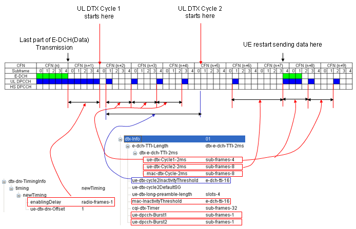
UL DPCCH burst pattern with a 2 ms E-DCH TTI. The bursts come every 4 subframes after the E-DCH data, every 8 subframes after 16 TTIs of inactivity, and the E-DCH data restarts on the MAC DTX cycle.
Continuous DPCCH before cycle 1 : the red arrow from enablingDelay = radio-frames-1 marks one radio frame of continuous UL DPCCH before "UL DTX Cycle 1 starts here". In 25.214, Enabling_Delay counts from the moment DTX is enabled, so this span belongs to the start of DTX.Cycle 1 sends a burst every 4 subframes : the UL DPCCH row shows a 1-subframe burst every 4 subframes, which is ue-dtx-Cycle1-2ms = sub-frames-4 with ue-dpcch-Burst1 = sub-frames-1.Cycle 2 starts after the inactivity threshold : the blue arrow from ue-dtx-cycle2InactivityThreshold spans the time without E-DCH data. At "UL DTX Cycle 2 starts here" the burst interval doubles to 8 subframes.E-DCH restarts on the MAC DTX cycle : the arrows from mac-dtx-Cycle-2ms = sub-frames-8 mark the 8-subframe grid, and "UE restart sending data here" falls on that grid. After the new data, the bursts return to the shorter cycle 1 spacing.
The ON time is the DPCCH burst : ue-dpcch-Burst1 and ue-dpcch-Burst2 set it, plus a short preamble and postamble.Cycle 2 follows inactivity : the UE moves to cycle 2 after the inactivity threshold and returns to cycle 1 at the end of an E-DCH transmission.The MAC DTX cycle limits when E-DCH may start : this lets the Node B receive discontinuously as well.
How does downlink DRX work ?
DRX is the downlink half of CPC. It decides in which subframes the UE monitors the HS-SCCH, and so in which subframes the Node B may schedule the UE on HS-DSCH.
Now let's look into DRX operation. The DRX cycle is specified as shown below. It seems a little bit simpler than DTX cycle configuration.
Excerpt of the same capture,
     | | +-drx-Info ::= SEQUENCE OPTIONAL:Exist
     | | | +-ue-drx-Cycle ::= ENUMERATED [sub-frames-10]
     | | | +-ue-drx-Cycle-InactivityThreshold ::= ENUMERATED [sub-frames-32]
The overall procedure is as follows.
i) UE gets into sleeping mode.
ii) UE wakes up when ue-drx-Cycle starts and stay up for one HS-SCCH subframe.
iii.a) If there is no HS-PDSCH data for the UE during the 'ON time', it gets into sleeping mode.
iii.b) If there is HS-PDSCH data for the UE during the 'ON time', UE continue to stay on for the duration of ue-drx-Cycle-InactivityThreshold.
iii.c) if there is another HS-PDSCH data for the duration of of ue-drx-Cycle-InactivityThreshold, ON-time get extended for another ue-drx-Cycle-InactivityThreshold from the reception of the data.
iii.d) repeat step iii.a)~iii.c)
iv) repeat the steps ii)~iii)
You may think 'why UE need to go through such a complicated process described in the step iii ?'. Logic is simple. If UE receives a data during the short period of 'ON-time', it is highly probably that there is another data coming right next TTI. So instead of getting into the sleeping mode right away just according to ue-drx-Cycle, it stay awake a little bit more not to cause too much delay for the downlink traffic.
The HS-SCCH reception pattern follows the same kind of rule as the DTX burst pattern. The UE monitors the HS-SCCH subframes where (5 x CFN_DRX - UE_DTX_DRX_Offset + S_DRX) mod UE_DRX_cycle = 0. DTX and DRX share one offset, and 25.331 requires UE DRX cycle to be a multiple or a divisor of UE DTX cycle 1. So the HS-SCCH reception subframes and the uplink DPCCH bursts line up. With ue-drx-Cycle = sub-frames-10 in the capture, the UE looks at the HS-SCCH once every 20 ms.
Even in DRX, the UE does not switch off every downlink channel. It keeps receiving the F-DPCH, and it receives the E-HICH for its own E-DCH transmissions. With ue-drx-GrantMonitoring = TRUE, it also monitors the E-AGCH and the E-RGCH when their subframe overlaps the start of an HS-SCCH reception subframe. After a scheduled E-DCH transmission, it monitors the grant channels fully for ue-GrantMonitoring-InactivityThreshold TTIs, which is e-dch-tti-8 in the capture.
The Node B can also switch DTX and DRX off and on without RRC, by HS-SCCH orders. The current 25.331 also offers a second DRX cycle in DRX-Info-r12. The UE moves to ue-drx-Cycle2 after a longer inactivity, in the same way as it moves to UE DTX cycle 2 on the uplink.
DRX is an HS-SCCH reception pattern : the UE monitors one HS-SCCH subframe per UE DRX cycle.Data keeps the UE awake : after an HS-SCCH or HS-PDSCH reception the UE monitors continuously for ue-drx-Cycle-InactivityThreshold subframes.F-DPCH and E-HICH are always received : grant channels follow ue-drx-GrantMonitoring and the grant monitoring threshold.
Reference
[1] 3GPP TS 25.214 v19.0.0 - clause 6C, Discontinuous transmission and reception procedures
[2] 3GPP TS 25.331 v19.0.1 - clauses 8.5.34, 8.6.6.39 and 10.3.6.34b, and the ASN.1 of clause 11.3
[3] 3GPP TS 25.321 v19.0.0 - clauses 11.8.1.4 and 11.8.1.8