A UE with a default bearer and one or more dedicated bearers has to decide, packet by packet, which bearer carries each IP packet. The P-GW has to make the same decision for downlink packets. A TFT is the rule set for that decision. Let's look at three things. The first is where the TFT sits in the bearer chain. The second is how the network sends it to the UE in a NAS message. The third is what a single packet filter inside it can match on.
- How does a TFT map a service data flow to an EPS bearer ?
- How is the TFT IE built in the NAS message ?
- Which packet filter components can a TFT carry ?
- Reference
How does a TFT map a service data flow to an EPS bearer ?
Before we look at the bytes, let's be clear about what a TFT decides. An EPS bearer gives one QoS treatment to every packet it carries. So traffic that needs a different QoS has to go on a different bearer, and something has to sort the packets. The TFT does that sorting at the two ends of the bearer.
TFT is a set of information structure that is used to map a Service Data Flows to a specific Radio Bearer. The high level view of the relationship between TFT and Radio Bearer is well illustrated as shown below in the WhitePaper : The LTE Network Architecture (A Comprehensive Tutorial) - Alcatel Lucent
The diagram below shows two EPS bearers, drawn in blue and green, between a UE and a P-GW. Service data flows arrive from the application layer at the top. The UL-TFT in the UE sorts uplink flows onto the bearers, and the DL-TFT in the P-GW sorts downlink flows. The nodes in between only map one bearer identifier to the next.
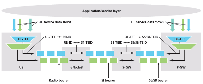
- UE : the UL-TFT maps each uplink service data flow to a radio bearer, shown as UL-TFT -> RB-ID.
- eNodeB : maps a radio bearer to an S1 bearer one to one, shown as RB-ID <-> S1-TEID. It does not look at the packet filters.
- S-GW : maps an S1 bearer to an S5/S8 bearer one to one, shown as S1-TEID <-> S5/S8-TEID.
- P-GW : the DL-TFT maps each downlink service data flow to an S5/S8 bearer, shown as DL-TFT -> S5/S8-TEID.
- Bottom labels : Radio bearer, S1 bearer and S5/S8 bearer are the three legs of each EPS bearer. The drawing spells the middle one as SI bearer, and it means the S1 bearer.
23.401 clause 4.7.2 describes the same split. The UL TFT is the set of uplink packet filters in a TFT, and the DL TFT is the set of downlink packet filters. Every dedicated EPS bearer has a TFT. The default bearer may have one, but it does not need one.
Now let's follow one uplink packet through the UE. The UE checks the uplink packet filters of all TFTs of the PDN connection together, in order of evaluation precedence. The filter with the lowest precedence value is checked first. At the first match, the UE sends the packet on the EPS bearer that owns the matching filter. If nothing matches, the UE sends the packet on the one EPS bearer that has no uplink packet filter, which is normally the default bearer. If every bearer has uplink filters, the UE discards the packet.
The P-GW runs the same algorithm for downlink packets with the downlink filters. For that reason the network keeps at most one EPS bearer without an uplink packet filter. The precedence values also let the operator force some traffic onto the default bearer. The operator gives the default bearer filters a lower precedence value than the dedicated bearer filters.
A TFT sorts packets onto EPS bearers : the UE applies the UL TFT, and the P-GW applies the DL TFT.The nodes in the middle never read the TFT : the eNodeB and the S-GW only map bearer identifiers one to one.Precedence is evaluated across all TFTs : the lowest evaluation precedence value wins, whichever bearer owns the filter.Unmatched traffic goes to the bearer without filters : and if every bearer has filters, the UE drops the uplink packet.
How is the TFT IE built in the NAS message ?
The network builds the TFT in the P-GW, but the UE needs the uplink part of it. So the TFT travels to the UE inside an ESM message such as ACTIVATE DEDICATED EPS BEARER CONTEXT REQUEST. The same IE also carries changes to an existing TFT, so let's read its header before its filters.
Overall structure of NAS message for TFT setting is as shown below. (This is an example case for specifying TFT to map a service data flow to a specific port. The structure of Packet Filter Component IE would vary depending on what you select in Packet Filter Component Type Identifier)
The screenshot below is a decoded ACTIVATE DEDICATED EPS BEARER CONTEXT REQUEST. The TFT is expanded, and it holds one packet filter. The green boxes on the right list the values that the decoder allows for the highlighted fields.
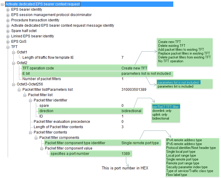
- Length of traffic flow template IE is 7. There is no IEI before it, because the TFT is a mandatory LV element in this message (24.301 Table 8.3.3.1).
- TFT operation code is Create new TFT, the E bit says that no parameters list is included, and the number of packet filters is 1. These three fields share one octet.
- The packet filter list is 31 00 03 50 13 89 in hex. The first octet, 0x31, carries the direction 11, bidirectional, and the packet filter identifier 1.
- The packet filter evaluation precedence is 0, and the length of the packet filter contents is 3 octets.
- The single component is 0x50, Single remote port type, and its value 0x1389 is port 5001 in decimal. So the filter matches traffic to or from remote port 5001 in both directions.
- The lists in the green boxes are the decoder's lists, not the full list of the current 24.008. They miss the Ignore this IE operation code and the newer component types in the table further down.
For the details of each of these parameters, refer to 24.008 10.5.6.12 Traffic Flow Template.
Let's start with octet 3, because it tells the receiver how to read the rest. Bits 8 to 6 are the TFT operation code, bit 5 is the E bit, and bits 4 to 1 are the number of packet filters. The table below lists the operation codes of 24.008 Table 10.5.162.
Bits 8 7 6 | TFT operation code | Packet filter list |
0 0 0 | Ignore this IE | empty |
0 0 1 | Create new TFT | complete packet filters |
0 1 0 | Delete existing TFT | empty |
0 1 1 | Add packet filters to existing TFT | complete packet filters |
1 0 0 | Replace packet filters in existing TFT | complete packet filters |
1 0 1 | Delete packet filters from existing TFT | packet filter identifiers only |
1 1 0 | No TFT operation | empty, a parameters list follows |
1 1 1 | Reserved | - |
The number of packet filters is 0 for Delete existing TFT and for No TFT operation. For every other operation it is from 1 to 15. Each complete packet filter then has four parts. The first octet carries the direction in bits 6 and 5 and the packet filter identifier in bits 4 to 1. The direction values are 00 for a pre Rel-7 filter, 01 for downlink only, 10 for uplink only and 11 for bidirectional. The next octet is the evaluation precedence, then one octet gives the length of the contents, and the contents follow.
The E bit adds a parameters list after the packet filters. 24.008 defines three parameters: 01H Authorization Token, 02H Flow Identifier and 03H Packet Filter Identifier. The third one lets the UE and the network point at existing filters when they change the QoS without changing the filters.
Watch the size limit when you build a large TFT. The IE is at most 257 octets, because one length octet counts the contents. A maximum size IPv4 filter is 36 octets, so only 7 of them fit in one IE. The network can still build a TFT of 16 filters by sending more of them with Add packet filters to existing TFT.
Octet 3 sets the operation : the operation code decides whether the list holds complete filters, identifiers only, or nothing.A filter is identifier, precedence, length and contents : the direction shares the first octet with the packet filter identifier.The same IE creates, changes and deletes a TFT : so always read the operation code before the filters.One IE holds at most 257 octets : large TFTs are built in steps with Add packet filters to existing TFT.
Which packet filter components can a TFT carry ?
A packet filter is a set of match conditions on the packet header. Each condition is one component: a one octet type identifier followed by a value of fixed length. So the type identifier also tells the receiver how many octets to read next. The table below is based on 24.008 v20.0.0 Table 10.5.162.
Type identifier | Component type | Value length |
0x10 | IPv4 remote address type | 8 octets - address and mask |
0x11 | IPv4 local address type | 8 octets - address and mask |
0x20 | IPv6 remote address type | 32 octets - address and mask |
0x21 | IPv6 remote address/prefix length type | 17 octets - address and prefix length |
0x23 | IPv6 local address/prefix length type | 17 octets - address and prefix length |
0x30 | Protocol identifier/Next header type | 1 octet |
0x40 | Single local port type | 2 octets |
0x41 | Local port range type | 4 octets - low and high limit |
0x50 | Single remote port type | 2 octets |
0x51 | Remote port range type | 4 octets - low and high limit |
0x60 | Security parameter index type | 4 octets |
0x70 | Type of service/Traffic class type | 2 octets - value and mask |
0x80 | Flow label type | 3 octets - 20 bit flow label |
0x81 | Destination MAC address type | 6 octets |
0x82 | Source MAC address type | 6 octets |
0x83 | 802.1Q C-TAG VID type | 2 octets - 12 bit VID |
0x84 | 802.1Q S-TAG VID type | 2 octets - 12 bit VID |
0x85 | 802.1Q C-TAG PCP/DEI type | 1 octet |
0x86 | 802.1Q S-TAG PCP/DEI type | 1 octet |
0x87 | Ethertype type | 2 octets |
In these names, local means the UE, and remote means the external network entity. That is why the example above uses Single remote port type for a server port. A single remote port is 1 octet of type and 2 octets of value, which gives the 3 octet contents length of the example.
24.008 also limits how the components combine. Each component type appears at most once in a filter. A filter carries only one of the IPv4 and IPv6 local address types, and only one of the two remote address types. It also carries only one of the single port and port range types on each side. The local address types need support from both the UE and the network. When both sides support them, the IPv6 remote address/prefix length type replaces the IPv6 remote address type. The Ethernet types from 0x81 to 0x87 serve PDN connections of Ethernet type. If the Ethertype is neither IPv4 nor IPv6, the filter carries no IP component at all.
A component is a type octet and a fixed length value : the type identifier tells the receiver the value length.Local is the UE side, remote is the far side : a server port on the internet is a remote port.Each type appears at most once per filter : and address and port types have exclusive pairs.Older decoders show a shorter list : the local address and Ethernet component types are later additions to the same table.
Reference
- 3GPP TS 24.008 v20.0.0 : Mobile radio interface Layer 3 specification; Core network protocols; Stage 3. Clause 10.5.6.12 Traffic Flow Template, Figure 10.5.144 and Table 10.5.162.
- 3GPP TS 24.301 v20.0.0 : Non-Access-Stratum (NAS) protocol for Evolved Packet System (EPS); Stage 3. Table 8.3.3.1 ACTIVATE DEDICATED EPS BEARER CONTEXT REQUEST and clause 9.9.4.16.
- 3GPP TS 23.401 v20.0.0 : General Packet Radio Service (GPRS) enhancements for Evolved Universal Terrestrial Radio Access Network (E-UTRAN) access. Clause 4.7.2 The EPS bearer.
- The LTE Network Architecture : A Comprehensive Tutorial, Alcatel Lucent white paper.