In the implementation of Carrier Aggregation, adding the SCell (SCC : Secondary Component Carrier) is conceptually not so complicated, but some complications are added in terms of some MAC/PHY operation like MAC Activation/Deactivation or CSI report. To control MAC/PHY operation in sophisticated manner, it became necessary to properly indentify the ID (index) of each cells. ServCellIndex and SCellIndex are RRC layer indicator to indentify each Cells in Carrier Aggregation and these Index are linked to MAC layer Cell IDs as will be described in this page.
SCellIndex
SCellIndex is used for itentifying each Secondary Cell (SCC : Secondary Component Carrier). It is configured in RRC message and mapped to MAC-CE for MAC Activation/Deactivation process as illustrated below.
The illustration below puts the two ends of that mapping side by side. At the top, an RRC Connection Reconfiguration adds one SCell in sCellToAddModList-r10, with sCellIndex-r10 set to 1. At the bottom is the one octet Activation/Deactivation MAC control element, with C7 to C1 and a reserved R bit. The arrow shows that sCellIndex 1 selects the C1 bit.
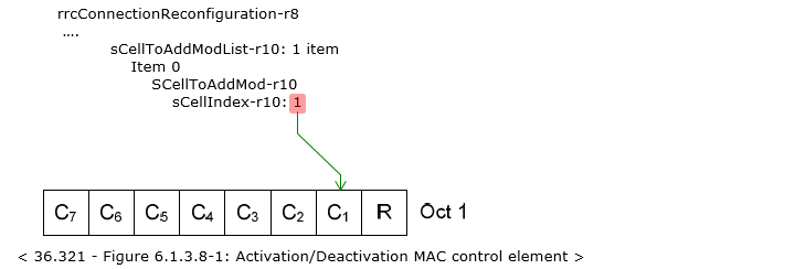
Figure 1. SCellIndex links an SCell in RRC to one bit of the Activation/Deactivation MAC control element. The eNB sets Ci to activate or deactivate the SCell with SCellIndex i.
Following 3GPP documents will give you the formal definition of SCellIndex and mapping between MAC-CE and SCellIndex.
36.331 - SCellIndex
The IE SCellIndex concerns a short identity, used to identify an SCell.
36.321 - 6.1.3.8 Activation/Deactivation MAC Control Element
The quotation below is from 36.321 v19.3.0. The wording has grown since Release 10, because later releases added the dormant state for an SCell and the Hibernation MAC control element.
Ci: if there is an SCell configured with SCellIndex i as specified in TS 36.331 [8], this field indicates the activation/deactivation status of the SCell with SCellIndex i, else the MAC entity shall ignore the Ci field. When the Ci field is set to "1", SCell with SCellIndex i shall be activated if it is in already activated state or deactivated state, otherwise the Ci field set to "1" shall be ignored. The Ci field is set to "0" to indicate that the SCell with SCellIndex i shall be deactivated
The range of SCellIndex decides how big this MAC control element has to be. SCellIndex-r10 runs from 1 to 7, so it fits the seven C fields of one octet. Release 13 added SCellIndex-r13, which runs from 1 to 31 for the larger number of carriers in Release 13 CA. The IE carries both ranges.
Following is based on
SCellIndex-r10 ::=                  INTEGER (1..7)
                SCellIndex-r13 ::=                  INTEGER (1..31)
36.321 v19.3.0 therefore defines two versions of the Activation/Deactivation MAC control element. The one octet version carries seven C fields and one R field. The four octet version carries 31 C fields and one R field. The MAC entity uses the one octet version when no serving cell has a ServCellIndex larger than 7, and the four octet version otherwise.
SCellIndex identifies an SCell, never the PCell : its range starts at 1.SCellIndex i maps to bit Ci : the eNB activates or deactivates that SCell with the Activation/Deactivation MAC control element.Up to SCellIndex 7, one octet is enough : with a higher ServCellIndex, the four octet MAC control element is used.
ServCellIndex
ServCellIndex means 'Serving Cell Index'. What is the serving Cell ? If it is Single Carrier (Non-Carrier Aggregation), the answer would be simple, but in case of CA(Carrier Aggregation), the term Serving Cell can be confusing. Does Serving Cell mean PCC (PCell, Primary Component Carrier) ? Not necessarily. It can be PCell only or PCell and SCell depending on the situation. Simply put, Serving Cell mean all of those cell (PCell or Scell or Both) that are currently in communication with a UE.
In most case, ServCellIndex in RRC Message is not specified and regarded to be 0 by default. The formal definition of ServCellIndex in 3GPP is as follows.
36.331 - ServCellIndex
The IE ServCellIndex concerns a short identity, used to identify a serving cell (i.e. the PCell or an SCell). Value 0 applies for the PCell, while the SCellIndex that has previously been assigned applies for SCells.
So ServCellIndex does not need a separate assignment. The PCell is always 0, and every SCell reuses its SCellIndex. The ranges follow the same two steps as SCellIndex, with one extra value for the PCell.
Following is based on
ServCellIndex-r10 ::=               INTEGER (0..7)
                ServCellIndex-r13 ::=               INTEGER (0..31)
One of the most common use case of ServCellIndex is in relation to CSI Report trigger setting as shown below. Each bit field of the Trigger indicates ServCellIndex and the bit field maps to PCell and each of the SCell as illustrated below.
The illustration below shows an aperiodicCSI-Trigger-r10 inside cqi-ReportAperiodic-r10, with trigger1-r10 set to 11000000 and trigger2-r10 set to 01000000. Under the bit strings, the leftmost bit is labelled PCell, the second bit is the SCell with ScellIndex = 1, and the last bit is the SCell with ScellIndex = 7. On the right, the same message adds the SCell with sCellIndex-r10 1.
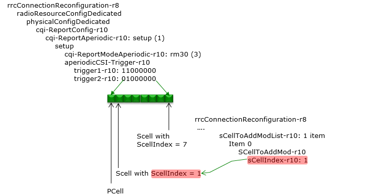
Figure 2. Each bit of an aperiodic CSI trigger stands for one serving cell, in ServCellIndex order. Bit 0 is always the PCell, and bit i is the SCell with SCellIndex i.
- 36.331 ties trigger1-r10 to the CSI request field value 10 and trigger2-r10 to the value 11 of 36.213 Table 7.2.1-1A.
- trigger1-r10 = 11000000 sets bit 0 and bit 1. So a DCI with CSI request field 10 asks for aperiodic CSI of the PCell and of the SCell with SCellIndex 1.
- trigger2-r10 = 01000000 sets only bit 1. So a DCI with CSI request field 11 asks for aperiodic CSI of the SCell with SCellIndex 1 only.
- At most 5 bits can be set to 1 in aperiodicCSI-Trigger-r10. The Release 13 version, aperiodicCSI-Trigger-v1310, uses 32 bit strings such as trigger1-r13 and trigger2-r13 to cover ServCellIndex 0 to 31. It ties them to 3 bit CSI request field values such as 010 and 011.
ServCellIndex covers every serving cell : 0 is the PCell, and an SCell uses its SCellIndex.The ServCellIndex of an SCell is its SCellIndex : RRC does not assign it separately.An aperiodic CSI trigger is a ServCellIndex bitmap : bit 0 on the left is the PCell.
Where else do these indexes appear ?
Activation and CSI triggering are the most visible uses, but they are not the only ones. Wherever a single DCI or a single MAC control element has to point at one of several serving cells, LTE reuses the same two indexes. So once you know the SCellIndex values from the RRC message, you can read several other fields directly.
The first is cross-carrier scheduling. CrossCarrierSchedulingConfig-r10 names the scheduling cell with schedulingCellId-r10, which is a ServCellIndex-r10. In the DCI, the carrier indicator field then selects the scheduled cell. 36.213 clause 9.1.1 states that the carrier indicator field value is the same as ServCellIndex, unless cif-InSchedulingCell-r13 is configured. In that case, the value comes from cif-InSchedulingCell-r13 instead.
The second is the Extended Power Headroom Report MAC control element in 36.321. It starts with a bitmap of Ci fields, like the Activation/Deactivation MAC control element. A Ci field set to 1 indicates that a PH field for the SCell with SCellIndex i is reported. So the bitmap tells the eNB which SCells the following PH fields belong to.
The carrier indicator field uses ServCellIndex by default : cif-InSchedulingCell-r13 can replace it with a configured value.The Extended PHR uses the same Ci bitmap as activation : bit Ci points to the SCell with SCellIndex i.One index serves RRC, MAC and PHY : the value set in sCellToAddModList is the value you meet in the MAC control elements and in the DCI.
Reference
- 36.331 v19.3.0 : E-UTRA Radio Resource Control - RRC; Protocol specification. SCellIndex, ServCellIndex, CQI-ReportConfig and CrossCarrierSchedulingConfig.
- 36.321 v19.3.0 : E-UTRA Medium Access Control - MAC; Protocol specification. Clause 6.1.3.6a Extended Power Headroom Report MAC Control Element, clause 6.1.3.8 Activation/Deactivation MAC Control Elements.
- 36.213 v19.4.0 : E-UTRA Physical layer procedures. Clause 9.1.1 PDCCH assignment procedure.